Advertisement
Quick Links
Advertisement

Related Manuals for ABB TMAX XT XT7


Summary of Contents for ABB TMAX XT XT7
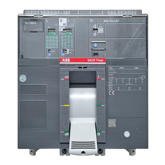
- Page 1 — INSTRUCTION HANDBOOK 1SDH002301A1001 - ECN000285442 TMAX XT XT7 Disassembly instructions...
-
Page 3: Safety Notes
(type Ekip DIP LS/I). Document is focused on Tmax XT XT7 3p IEC version, anyway it allows to cover other versions of Tmax XT XT7 circuit breaker with just few slight differences to be taken into account. -
Page 4: Disassembly Process
INSTRUCTION HANDBOOK 5. SEPARATE TREATMENT Table below lists parts requiring a separate treatment adding information about part location inside circuit breakers and related quantity. Description Position inside circuit breaker Quantity Cap kits In correspondence of circuit breaker connection terminals Support Mounted on the upper part of the circuit breaker Cables protection Mounted on the back part of the trip unit... - Page 5 Disassembly instruction tmaX Xt Xt7 6.1 PHASE 1 – CAP KITS Tools Actions to be performed Cross screwdriver Manually remove the terminal clamp. By means of the cross screwdriver unscrew the 2 screws fixing the terminal clamp to the circuit breaker main structure.
- Page 6 INSTRUCTION HANDBOOK By means of the flat screwdriver remove the nuts mounted on the cap kits. Disassembled parts • 1 terminal clamp (Plastic) • 2 screws (Metal) • 12 screws and related washers (Metal) • 12 plates (Metal) • 6 cap kits (Plastic) SEPARATE TREATMENT (Thermoplastics containing brominated flame retardants) • 12 nuts (Metal)
- Page 7 Disassembly instruction tmaX Xt Xt7 6.2 PHASE 2 – CIRCUIT BREAKER FRONT COVER AND OPERATING MECHANISM COVER Tools Actions to be performed Cross screwdriver Manually push the trip unit transparent Manually close the circuit breaker pushing the Pliers protection as indicated by the arrow and toggle in the direction indicated by the arrow.
- Page 8 INSTRUCTION HANDBOOK Manually lift the circuit breaker front cover to By means of the pliers remove the trip test complete the removal. button. Manually remove the upper keylock cap. By means of the tork key remove the 4 screws fixing the 2 keylock caps to the circuit breaker front cover.
- Page 9 Disassembly instruction tmaX Xt Xt7 By means the cross screwdriver, unscrew the Manually lift the operating mechanism cover. 2 screws located in the bottom part of the operating mechanism front cover fixing the operating mechanism cover to the circuit breaker main structure.
- Page 10 INSTRUCTION HANDBOOK 6.3 PHASE 3 – TRIP UNIT Tools Actions to be performed Cross screwdriver By means of a cross screwdriver unscrew the 2 Manually remove the support. Torx key screws fixing the support to the circuit breaker main structure. No.
- Page 11 Disassembly instruction tmaX Xt Xt7 Manually push the cables protection as By means of the flat screwdriver disconnect indicated by the arrow and remove it. the connector from the trip unit and after manually complete the removal of the trip unit.
- Page 12 INSTRUCTION HANDBOOK By means of the cutter start removing the By means of the torx key (size 8) unscrew the 2 label located on the front of the trip unit and screws fixing the backplane to the trip unit and manually complete the operation.
- Page 13 Disassembly instruction tmaX Xt Xt7 By means of the pliers remove the “i TEST” pushbutton from the trip unit case. Disassembled parts • 1 support (Plastic) SEPARATE TREATMENT (Thermoplastics containing brominated flame retardants) • 2 + 2 + 2 + 2 + 4 screws (Metal) • 1 cables protection (Plastic) SEPARATE TREATMENT (Thermoplastics containing brominated flame retardants) • 1 rating plug case (Plastic) SEPARATE TREATMENT...
- Page 14 INSTRUCTION HANDBOOK 6.4 PHASE 4 – ASSEMBLIES MOUNTED ON CIRCUIT BREAKER LEFT SIDE Tools Actions to be performed Cross screwdriver By means of the cross screwdriver unscrew the Manually remove the left MID. 2 screws fixing left MID to the circuit breaker Torx key main structure.
- Page 15 Disassembly instruction tmaX Xt Xt7 Manually pull the left base group as indicated By means of the cross screwdriver unscrew the by the arrow and after complete the removal. screw fixing the guide plate pin to the left base group.
- Page 16 INSTRUCTION HANDBOOK Manually separate the spring from the pin By means of the cross screwdriver unscrew the removed at picture 46. 3 screws fixing the trip coil group to the circuit breaker main structure. By means of the flat screwdriver unhook the Manually remove the trip coil group pulling it in connector from the trip coil group.
- Page 17 Disassembly instruction tmaX Xt Xt7 By means of the flat screwdriver push out from the trip coil group the trip coil. Disassembled parts • 2 + 2 + 2+ 2 + 1 + 3 + 1 screws (Metal) • 1 left MID cover (Plastic) SEPARATE TREATMENT (Thermoplastics containing brominated flame retardants) • 1 left MID (Plastic, Metal and Electronic components) SEPARATE TREATMENT (Printed circuit board) • 1 left base (Plastic) SEPARATE TREATMENT (Thermoplastics containing brominated flame retardants) • 1 guide plate pin (Metal)
- Page 18 INSTRUCTION HANDBOOK 6.5 PHASE 5 – ASSEMBLIES MOUNTED ON CIRCUIT BREAKER RIGHT SIDE Tools Actions to be performed Torx key By means of the torx key unscrew the screw By means of the cross screwdriver unscrew the fixing the trip test group to the operating screw located in the upper part of the MID.
- Page 19 Disassembly instruction tmaX Xt Xt7 Manually lift and remove the shunt opening By means of the cross screwdriver unscrew release plug. the screw fixing the MID to the circuit breaker main structure. Manually complete the removal of the MID. Manually remove the auxiliary contacts lever mounted on the MID.
- Page 20 INSTRUCTION HANDBOOK Manually remove the wires cover and the wiring. Disassembled parts • 1 + 1 + 2 + 2 + 1 + 1 screws (Metal) • 1 trip test support (Plastic) SEPARATE TREATMENT (Thermoplastics containing brominated flame retardants) • 1 plate (Metal) • 1 shunt opening release plug (Plastic) • 1 MID (Plastic, Metal and Electronic components) SEPARATE TREATMENT (Printed circuit board) • 1 auxiliary contacts lever (Metal) • 1 SY lever (Plastic) SEPARATE TREATMENT (Thermoplastics containing brominated flame retardants) • 1 wires cover (Plastic) SEPARATE TREATMENT (Thermoplastics containing brominated flame retardants) • 1 wiring (Plastic and Metal) SEPARATE TREATMENT (Thermoplastics containing brominated flame...
- Page 21 Disassembly instruction tmaX Xt Xt7 6.6 PHASE 6 – OPERATING MECHANISM Tools Actions to be performed Flat screwdriver By means of the flat screwdriver lift the lever By means of the flat screwdriver remove the Allen key mounted on the left side of the circuit breaker cover cap on the left side of the circuit breaker.
- Page 22 INSTRUCTION HANDBOOK Manually open the circuit breaker. Manually close the circuit breaker. By means of the allen key unscrew the 2 screws By means of the flat screwdriver push the shaft located on the left side of the operating support as indicated by the arrow. mechanism.
- Page 23 Disassembly instruction tmaX Xt Xt7 By means of the allen key unscrew the 2 screws By means of the flat screwdriver push the shaft located on the right side of the operating support as indicated by the arrow. mechanism. Put the circuit breaker with the left side up and Push down the rod using the hammer.
- Page 24 INSTRUCTION HANDBOOK Put the circuit breaker with front up and push Manually push the lever mounted on the right the rod as indicated by the arrow until the pin side of the operating mechanism in order to comes out from the hole left by the cover cap put the circuit breaker in trip position.
- Page 25 Disassembly instruction tmaX Xt Xt7 Manually remove the rear plate mounted on the By means of the torx key (size 25) unscrew the lower part of the circuit breaker. 6 screws located in the back part of the circuit breaker.
- Page 26 Operating mechanism contains springs: their removal constitutes a potential hazard if not performed in the proper way and using dedicated tools. Based on this ABB indication is not to remove them from the operating mechanism and to manage the assembly with the maximum level of attention during disassembly and dismantle phases.
- Page 27 Disassembly instruction tmaX Xt Xt7 Manually remove the toggle extension Disassembled parts • 1 lever (Metal) • 1 lever (Plastic and Metal) • 2 cover caps (Plastic) • 4 + 9 + 6 + 6 + 2 + 1 screws (Metal) • 1 pin (Metal) • 2 rear plates (Plastic) • 1 upper case assembly (Plastic and Metal) * • 1 operating mechanism (Plastic and Metal) SEPARATE TREATMENT (Thermoplastics containing brominated flame retardants) • 2 unlocking shaft appendices (Plastic) SEPARATE TREATMENT (Thermoplastics containing brominated flame retardants) • 1 lever extension (Plastic) SEPARATE...
- Page 28 INSTRUCTION HANDBOOK 6.7 PHASE 7 – UPPER CASE ASSEMBLY AND UPPER FIXED CONTACTS Tools Actions to be performed Allen key Manually remove the 2 protections located in By means of the allen key unscrew the 6 screws the upper part of the upper case assembly. fixing the fixed contacts and make them fall down by gravity.
- Page 29 Disassembly instruction tmaX Xt Xt7 By means of the cross screwdriver unscrew the 2 screws fixing the fixed contact protection to the upper fixed contact and manually complete the removal operation. Disassembled parts • 2 protections (Plastic) SEPARATE TREATMENT (Thermoplastics containing brominated flame retardants) • 6 + 3 + 6 screws (Metal)
- Page 30 INSTRUCTION HANDBOOK 6.8 PHASE 8 – LOWER CASE ASSEMBLY, MOVING CONTACTS ASSEMBLY AND SENSORS Tools Actions to be performed Cutter By means of the cutter start removing the label Manually lift the lower case assembly and located on the side of the lower case assembly complete the removal and manually complete the removal.
- Page 31 Disassembly instruction tmaX Xt Xt7 By means of the flat screwdriver lift the Manually remove the moving contacts moving contacts assembly until it’s unhooked assembly. from the lower case. By means of the flat screwdriver unhook from both sides the insulation protections and after manually complete the removal.
- Page 32 INSTRUCTION HANDBOOK 6.9 PHASE 9 – ARCHING CHAMBERS AND CIRCUIT BREAKER COVER Tools Actions to be performed Cutter Manually remove the arching chambers. By means the cutter, lift the label located on the side of the circuit breaker cover and Flat screwdriver manually complete the removal.
- Page 33 Disassembly instruction tmaX Xt Xt7 By means of the flat screwdriver remove the plug from the circuit breaker cover base structure. Disassembled parts • 3 arching chambers (Plastic and Metal) • 3 labels (Adhesive paper) • 1 plug (Plastic) • 1 circuit breaker cover (Plastic)
- Page 34 INSTRUCTION HANDBOOK 7. ENERGY CONSUMPTION FOR CIRCUIT BREAKERS DISASSEMBLY Since all disassembly operations illustrated in this document are manual, the CO equivalent emissions can be considered null/negligible.
- Page 35 Disassembly instruction tmaX Xt Xt7...
- Page 36 — ABB SACE A division of ABB S.p.A. L.V. Breakers Via Pescaria 5, 24123 Bergamo - Italy Phone: +39 035 395.111 Fax: +39 035 395.306-433 abb.it/lowvoltage © Copyright 2022 ABB. All rights reserved. Specifications subject to change without notice.