Table of Contents
Advertisement
Quick Links
Advertisement
Table of Contents

Related Manuals for ABB VAC D500


Summary of Contents for ABB VAC D500
- Page 1 Commissioning Instruction CI/EDP300-EN Rev. A D500 Electro-Pneumatic Positioner...
- Page 2 205-678-0507 Office 205-678-0510 Fax www.vacaccessories.com © Copyright 2012 by ABB Subject to changes without notice This document is protected by copyright. It assists the user in safe and efficient operation of the device. The contents of this document, whether whole or in part, may not be copied or reproduced without prior approval by the copyright holder.
-
Page 3: Table Of Contents
Change from one to two columns 7.2.2 Switching to the information level (Operator Menu) Contents ................24 7.2.3 Start Auto Adjust function ........25 Safety................4 7.2.4 Switching the operating mode......26 General information and notes for the reader..4 7.2.5 Switching to the configuration level Intended use............ -
Page 4: Safety
Safety Intended use Positioning of pneumatically controlled actuators; designed for hange from one to two columns mounting on linear and part-turn actuators. General information and notes for the reader The device is designed for use exclusively within the stated You must read these instructions carefully prior to installing values on the name plate and in the specifications (see the and commissioning the device. -
Page 5: Plates And Symbols
Plates and symbols CAUTION – Minor injuries 1.4.1 Safety / warning symbols, note symbols This symbol in conjunction with the signal word "CAUTION" indicates a potentially dangerous DANGER – Serious damage to health / risk to situation. Failure to observe this safety life information may result in minor or moderate This symbol in conjunction with the signal word... -
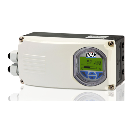
Page 6: Name Plate
Change from two to one column 1.4.2 Name plate Fig. 1: Name plate (sample) 1 Full type designation | 2 Order code | 3 Serial number | 4 Special version | 5 Hardware revision / Software revision | 6 Date of manufacture | 7 Explosion protection | 8 Manufacturer | 9 Supply pressure | 10 Input signal | 11 Ambient temperature range | 12 Output | 13 Safety function (no current) | 14 Communication protocol | 15 Degree of protection | 16 Options Change from one to two columns Transport safety instructions... -
Page 7: Installation Safety Instructions
Adjust before restoring the factory settings. All devices delivered to ABB must be free from any hazardous materials (acids, alkalis, solvents, etc.). — Only qualified specialists who have been trained for these tasks are authorized to mount and adjust the unit, and to Please contact Customer Center Service acc. -
Page 8: 1.12 Disposal
If it is not possible to dispose of old equipment properly, ABB ElektroG. If the necessary components are available on the Service can accept and dispose of returns for a fee. -
Page 9: Use In Potentially Explosive Atmospheres
Use in potentially explosive IMPORTANT (NOTE) Use in areas with combustible dust atmospheres — To prevent loss of its type of protection, the Change from one to two columns housing may not be opened. Depending on the type of explosion protection, an Ex name —... -
Page 10: Mounting
Change from one to two columns Mounting CAUTION – Minor injuries Incorrect parameter valves can cause the valve to move unexpectedly. This can lead to process failures and result in injuries. Before recommissioning a positioner that was previously in use at another location, always reset the device to its factory settings. -
Page 11: Mounting On Linear Actuators
Attaching a follower guide to the actuator 3.2.2 Mounting on linear actuators For mounting on a linear actuator in accordance with DIN / IEC 534 (lateral mounting as per NAMUR), the following mounting kit is available: Fig. 5 1. Tighten the screws so that they are hand-tight. 2.... - Page 12 Positioner linkage Mounting on a cast iron yoke Fig. 7 1. Attach the mount bracket (2) with screw (4) and shim (3) to the cast iron yoke (1). Fig. 9 1 Increasing linkage | 2 Reducing linkage The scale on the lever indicates the link points for the various Mounting on a columnar yoke stroke ranges of the valve.
-
Page 13: Mounting On Part-Turn Actuators
Integral mounting on control valves 3.2.3 Mounting on part-turn actuators For mounting on part-turn actuators in accordance with VDI / VDE 3845, the following mounting kit is available: Fig. 10 1 Shims | 2 Screws | 3 O-ring | 4 Lever Integral mounting on control valves using adapter plate Fig. - Page 14 Screwing positioner onto actuator Mounting the adapter on the positioner Fig. 13 1. Determine the mounting position (parallel to actuator or at 90° angle). 2. Determine the direction of rotation of the actuator (clockwise or counter-clockwise). 3. Move the part-turn actuator into the home position. 4....
-
Page 15: Electrical Connections
Change from two to one column Electrical connections IMPORTANT (NOTE) The cable terminals are delivered closed and must be unscrewed before inserting the cable. 1. Strip the wire by approx. 6 mm (0.24 inch). 2. To connect the signal lines, the emergency shutdown module, and the proximity switches or microswitches, insert the wire ends from the left into the respective screw terminals and tighten the screws so that they are hand-tight (access from above). -
Page 16: Cable Entry
Change from one to two columns Cable entry 4.3.1 Installing the pressure option For the cable entry in the housing, there are two tap holes 1/2 - 14 NPT or M20 x 1.5 on the left-hand side of the housing. One of these holes has a cable gland and the other has a pipe plug. -
Page 17: Setting The Mechanical Binary Feedback With Proximity Switches
4.4.2 Setting the mechanical binary feedback with 4.4.3 Setting the mechanical binary feedback with 24 V proximity switches microswitches 1. Loosen the screws for the housing cover and remove it. 1. Loosen the screws for the housing cover and remove it. 2.... -
Page 18: Pneumatic Connection
Pneumatic connection Connect the connections according to their labeling: hange from one to two columns Designation Pipe connection IMPORTANT (NOTE) SUP / ZUL IN Air supply, pressure 1.4 ... 10 bar The positioner must only be supplied with (20 ... 145 psi) instrument air that is free of oil, water, and dust (in the gas exhaust with dried natural gas). -
Page 19: Commissioning
Commissioning 6.2.2 Moving to end positions with a new device Process display hange from one to two columns During commissioning, the mechanical mounting on the linear and part-turn actuators is checked. For this purpose, the actuator is first moved into the end positions and Auto Adjust is then carried out. -
Page 20: Configuration, Parameterization
Configuration, parameterization Control button functions hange from one to two columns Meaning Operation The LCD display features operating buttons which enable the Exit Exit menu device to be operated with the housing cover open. Back Go back one submenu Abort Cancel a parameter entry Next Select the next position for entering numerical... -
Page 21: Menu Levels
Menu levels There are two levels under the process display. Process display Information level Operating modes menu Diagnostics Auto Adjust Operator Page 1 Adaptive Signal View Control Manual SP Manual Sensor Configuration Configuration level Easy Setup Device Setup Display Control Input / Output Communication Diagnostics... -
Page 22: Process Display
7.2.1 Process display Description of operating modes Symbol Operating mode 50.0 Adaptive control active When the PositionMaster EDP300 positioner is Position operated in "Adaptive Mode", the control parameters are automatically optimized to the operating conditions in small increments. This is especially helpful if valves and fittings could not be operated with reference conditions while the Auto M10240... - Page 23 Description of the message symbols Symbol Operating mode Manual setpoint, fixed control The valve is adjusted manually within the stroke Symbol Message symbol range using the direction buttons. Universal input activated 1. Press and hold the relevant operating button for the desired direction.
-
Page 24: Switching To The Information Level (Operator Menu)
7.2.2 Switching to the information level (Operator Menu) Error messages On the information level, the operator menu can be used to In the event of an error, a message consisting of a symbol and display diagnostic information and choose which operator text (e.g., electronics) appears at the bottom of the process pages to display. -
Page 25: Start Auto Adjust Function
Calling up the error description Operating Mode Additional details about the error that has occurred can be Auto Adjust Adaptive called up on the information level. Control Manual SP Manual Sensor Configuration Process display Back 2. Use to select the "Auto Adjust" operating mode. -
Page 26: Switching The Operating Mode
7.2.4 Switching the operating mode Parameter Name Parameter 1 The operating mode is displayed and changed in the operating modes menu. Parameter 2 Additionally, it is possible to switch to the configuration level Parameter 3 from there. Cancel 3. Use to select the required value. -
Page 27: Overview Of Parameters On The Configuration Level27
Change from two to one column Overview of parameters on the configuration level IMPORTANT (NOTE) This overview of parameters shows all the menus and parameters available on the device. Depending on the version and configuration of the device, not all of the menus and parameters may be visible on it. Easy Setup Actuator Type Vent Position %... - Page 28 Analog Out Min. ANALOG FEEDBACK Analog Out Max. Feedbk. Charact AO ALARM MASK Alarm Maintenan. Alarm OoSpec. AO Simulation Alarm Check Fct. Alarm Failure DIGITAL FEEDBACK SWITCH 1 Switch 1 Funct. Switch 1 Value Switch 1 Logic Switch 1 Active Switch 1 Sim.
- Page 29 Diagnostics PARTIAL STROKE PS CONFIGURATION PS Interval PS Start Now HISTOGRAM Position Timeout Valve Movements Travel Counter Valve Cycles Movement Counter Mainly Used Pos. Reset Histograms Universal Input Reset Status Device Info. Hardware Rev. Software Rev. Mounting Date Communication Tag Long Tag (HART7 only) Device Address Descriptor...
-
Page 30: Ex Relevant Specifications
Change from one to two columns Ex relevant specifications Shutdown module (terminals +41 -42) Temperature class T1 – T6 Intrinsic safety gas and dust ATEX / IECEx = 30 V ZELM 11 ATEX 0456 X (EC type examination certificate) = 1 W II 1G Ex ia IIC T6 or T4 Ga = 5.3 nF II 1D Ex iaD IIIC T55°C or T100°C Da... -
Page 31: Equipment In Type Of Protection "N" Or Device Dust Ignition Protection Through Housing "Tb
Equipment in type of protection "n" or device dust Electrical connections non-sparking ATEX/IECEx ignition protection through housing "tb" Equipment in type of protection "n" or device dust ignition protection through housing "tb" ZELM 11 ATEX 0456 X (EC type examination certificate) II 3G Ex nA IIC T6 or T4 Gc Signal circuit (AI) (terminals +11 -12): II 2D Ex tb IIIC T55°C or T100°C Db... -
Page 32: Appendix
D500 | CI/EDP300-EN Rev. A 33...