Siemens SIMATIC ET 200SP HA System Manual
Distributed i/o system
Hide thumbs
Also See for SIMATIC ET 200SP HA:
- Compact operating instructions (181 pages) ,
- Original instructions manual (165 pages) ,
- System manual (146 pages)
Table of Contents
Advertisement
SIMATIC
ET 200SP HA
ET 200SP HA Distributed I/O system
System Manual
08/2019
A5E39261167-AD
Security information
Preface
System overview
Plant planning
Installation
Wiring
Removal
Maintenance
Technical specifications
Dimension drawings
Accessories/spare parts
Leakage resistance of the IO
device
Service & Support
1
2
3
4
5
6
7
8
9
A
B
C
D
Advertisement
Table of Contents

Related Manuals for Siemens SIMATIC ET 200SP HA


Summary of Contents for Siemens SIMATIC ET 200SP HA
- Page 1 Security information Preface System overview SIMATIC Plant planning ET 200SP HA ET 200SP HA Distributed I/O system Installation Wiring System Manual Removal Maintenance Technical specifications Dimension drawings Accessories/spare parts Leakage resistance of the IO device Service & Support 08/2019 A5E39261167-AD...
- Page 2 Note the following: WARNING Siemens products may only be used for the applications described in the catalog and in the relevant technical documentation. If products and components from other manufacturers are used, these must be recommended or approved by Siemens. Proper transport, storage, installation, assembly, commissioning, operation and maintenance are required to ensure that the products operate safely and without any problems.
-
Page 3: Table Of Contents
Documentation guide for ET 200SP HA.................12 2D matrix code (QR code / EAN code) ..................14 System overview ............................15 What is the SIMATIC ET 200SP HA distributed I/O system? ..........15 Basic components of the IO device..................17 Accessories for the IO device ....................21 Plant planning.............................23... - Page 4 Table of contents Mounting the interface module....................66 Mounting an carrier module for I/O module slots ..............68 Installing the terminal block....................71 Installing the server module and power bus cover..............73 Wiring .................................75 Markings of IO device components..................75 6.1.1 Factory markings........................75 6.1.2 Optional markings ........................76 6.1.3 Applying color-coded labels ....................77 6.1.4...
- Page 5 Table of contents Resetting the interface module to factory settings ...............129 Firmware update for interface modules / I/O modules ............131 8.10 Firmware update for the server module ................132 Technical specifications..........................133 Standards and approvals .....................133 9.1.1 Currently valid markings and approvals ................133 9.1.2 CE marking ..........................134 9.1.3...
- Page 6 Table of contents ET 200SP HA Distributed I/O system System Manual, 08/2019, A5E39261167-AD...
-
Page 7: Security Information
Siemens’ products and solutions undergo continuous development to make them more secure. Siemens strongly recommends that product updates are applied as soon as they are available and that the latest product versions are used. Use of product versions that are no longer supported, and failure to apply the latest updates may increase customer’s exposure to cyber... - Page 8 Security information ET 200SP HA Distributed I/O system System Manual, 08/2019, A5E39261167-AD...
-
Page 9: Preface
Preface Purpose of the documentation This documentation provides comprehensive information on using the ET 200SP HA distributed I/O system in the automation system: ● General information on the ET 200SP HA distributed I/O system ● Configuring ● Installation ● Wiring ●... - Page 10 ● Information about the technical support available can be found in the appendix to this documentation (Page 175). ● The technical documentation for the individual SIMATIC products and systems is available on the Internet (http://www.siemens.com/simatic-tech-doku-portal). ● The online catalog and the ordering system are available on the Internet (https:// mall.industry.siemens.com).
- Page 11 Changes compared to the previous version You can find an overview of the most important changes here: ● V1.2 or higher: – Counter function integrated – Additional approvals See also Contact (http://support.industry.siemens.com/aspa_app/) ET 200SP HA Distributed I/O system System Manual, 08/2019, A5E39261167-AD...
-
Page 12: Documentation Guide For Et 200Sp Ha
2.1 Documentation guide for ET 200SP HA Documentation guide for ET 200SP HA The documentation for the distributed I/O system SIMATIC ET 200SP HA is divided into three areas. This division allows you easier access to the specific information you require. - Page 13 You can find the full versions of the documentation as of PCS 7 V9.0 as downloads for the "Technical Documentation of SIMATIC PCS 7" on the Internet (http://www.siemens.com/pcs7- documentation): Technical documentation SIMATIC PCS 7 > "Manuals for SIMATIC PCS 7 Vx.x" area >...
-
Page 14: Matrix Code (Qr Code / Ean Code)
The 2D matrix code on the product is a coded representation of the product-specific article number. Access to product-related information For reading the 2D matrix code, SIEMENS offers an app for mobile use. Information about the app and the download can be found on the Internet: "Mobile use via app (https://support.industry.siemens.com/cs/ww/en/sc/2067)". -
Page 15: System Overview
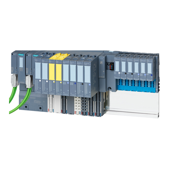
What is the SIMATIC ET 200SP HA distributed I/O system? The SIMATIC ET 200SP HA distributed I/O system is a scalable and highly flexible I/O system that enables you to connect process signals to a higher-level controller via PROFINET IO. - Page 16 Configuration example For use in an automation system, you combine the following components of the SIMATIC ET 200SP HA distributed I/O system into an IO device. An example configuration of an IO device is shown in the following figure: Figure 3-1...
-
Page 17: Basic Components Of The Io Device
System overview 3.2 Basic components of the IO device Basic components of the IO device Basic components for configuration of IO devices The following tables show the components for configuring IO devices based on the ET 200SP HA distributed I/O. Table 3-2 Rail Function... - Page 18 The BusAdapters for PROFINET IO allow you to freely choose the connection system for the IO device. Several versions of the BusA‐ dapter are available for the interface modules (see documentation SIMATIC Distributed I/O; BusAdapter for distributed I/O (https:// support.industry.siemens.com/cs/ww/en/view/109747250)): Examples: ● BusAdapter with standard RJ45-connector ① (BusAdapter 2×RJ45) ●...
- Page 19 System overview 3.2 Basic components of the IO device Table 3-7 Terminal block Function Figure The selection of terminal blocks determines the following properties: ● Type of supply voltage ● Formation of potential groups ● Type of the required I/O module ●...
- Page 20 I/O module with another type (Page 123)". Component for the supply voltage You can find information on suitable components on the Internet (https:// Interactive Catalog CA01; support.industry.siemens.com/cs/ww/en/view/9172884): Automation and Drives ET 200SP HA Distributed I/O system System Manual, 08/2019, A5E39261167-AD...
-
Page 21: Accessories For The Io Device
System overview 3.3 Accessories for the IO device Accessories for the IO device The following accessories are available for SIMATIC ET 200SP HA: Table 3-12 Shield connector Function Figure The shield connector allows the low-impedance contacting of cable shields with minimum installation times. - Page 22 System overview 3.3 Accessories for the IO device ET 200SP HA Distributed I/O system System Manual, 08/2019, A5E39261167-AD...
-
Page 23: Plant Planning
Plant planning Topology An overview of various options for setting up a PROFINET network is given below. Linear All the communication nodes are connected in a linear bus topology. Line If a connecting element (for example switch) fails, data exchange beyond the failed connecting element is no longer possible. - Page 24 PROFINET IO networks via PN/PN coupler. Additional information You can find more detailed information in the SIMATIC NET manual Communication with SIMATIC (https://support.industry.siemens.com/cs/ww/en/view/1254686). You should also read the PROFINET Installation Guideline from the PROFIBUS User Organization (http://www.profibus.com/download/).
-
Page 25: Basics
Plant planning 4.2 Basics Basics In accordance with the standards for electrical devices, all components of the ET 200SP HA distributed IO system are classified as open equipment. Note You must ensure the following for the operation of the ET 200SP HA: ●... -
Page 26: Special Conditions For Safe Use Of The Et 200Sp Ha
Plant planning 4.3 Special conditions for safe use of the ET 200SP HA Special conditions for safe use of the ET 200SP HA The ET 200SP HA must be installed in a suitable enclosure which ensures at least IP 54 degree of protection according to EN 60529. -
Page 27: Potential Relationships In The Io Device
Plant planning 4.4 Potential relationships in the IO device Potential relationships in the IO device The following potential relationships apply in the IO device based on the ET 200SP HA distributed IO system: ● Same potential: – The same potential only exists for the supply voltages of I/O modules of one potential group. -
Page 28: Hardware Configuration
Plant planning 4.5 Hardware configuration Hardware configuration Maximum mechanical configuration As soon as one of the following rules applies, the maximum configuration has been reached for an IO device based on the ET 200SP HA distributed I/O: Table 4-1 Maximum mechanical configuration Properties Rule Number of modules Maximum 56 slots for I/O modules, regardless of their use... - Page 29 The permissible cable length between nodes on PROFINET depends on the following factors: ● Cable types (electrical/optical) ● Transmission paths (use of amplifiers/repeaters) You can find information on this in the Catalog ST PCS 7 on the Internet (https:// support.industry.siemens.com/cs/ww/en/view/9172884). ET 200SP HA Distributed I/O system System Manual, 08/2019, A5E39261167-AD...
-
Page 30: Selecting The Carrier Module
Plant planning 4.6 Selecting the carrier module Selecting the carrier module Carrier modules for interface modules (types) You determine the type of carrier modules based on availability requirements. Carrier modules for interface modules are available in ET 200SP HA in following versions: ●... - Page 31 Plant planning 4.6 Selecting the carrier module Additional information ● You can find the article numbers in the section "Accessories/spare parts (Page 171)". ● You can find information on the function and design of the carrier modules in the manual (for download, see "Documentation guide for ET 200SP HA (Page 12)") ET 200SP HA Distributed I/O system System Manual, 08/2019, A5E39261167-AD...
-
Page 32: Configurations Of The Slots Of I/O Modules
Plant planning 4.7 Configurations of the slots of I/O modules Configurations of the slots of I/O modules 4.7.1 Selecting a terminal block for I/O modules Table 4-3 ET 200SP HA TERMINAL BLOCKS Category Type Color Article number Short Properties ET 200SP TYPE LIGHT 6DL1193-6TP0... - Page 33 Plant planning 4.7 Configurations of the slots of I/O modules I/O module ET 200SP HA TERMINAL BLOCK (TYPE) 24V St TB 24V Red TB 24V L+ TB 24V M TB (N0) Isol TB (K0) (H1) (M1) (P0) RQ 4x230/5A CO DI-AI 16x / DQ16x Optional Optional...
-
Page 34: Forming Potential Groups
Plant planning 4.7 Configurations of the slots of I/O modules TBxxZ-Kyy+n_/T Meaning Infeed: Number of supply terminal and type e.g. 32x24V+4M: 32 supply terminals for 24V and 4 supply terminals for ground B=Power bus is connected to the left module D=Power bus is interrupted to the left T=Temperature detection possible (This marking is only available for terminal blocks with temperature detection.) - Page 35 Plant planning 4.7 Configurations of the slots of I/O modules Extending the potential group ● Each dark-colored terminal block passes the supply voltage connected on the light-colored terminal block to the I/O modules and to the dark terminal block positioned to the right of it. ●...
- Page 36 Plant planning 4.7 Configurations of the slots of I/O modules Example for the configuration of an IO device Carrier module IM Light-colored terminal block BusAdapter Dark-colored terminal block Interface module (IM) Carrier module 8x Supply voltage L+ of the IM Carrier module 2x Potential group 1 Supply voltage L+ (of potential group 1)
-
Page 37: Configuration Examples For Potential Groups
Plant planning 4.7 Configurations of the slots of I/O modules Potential group 4 Supply voltage L+ (of potential group 4) ⑤ ● Carrier module 2x Backplane bus (hidden) Server module Power bus and power bus cover Figure 4-1 Example for positioning terminal blocks 4.7.2.2 Configuration examples for potential groups The following tables show basic configuration examples with I/O modules on terminal blocks. - Page 38 Plant planning 4.7 Configurations of the slots of I/O modules Table 4-6 Configuration example for terminal blocks with 32 process terminals Terminal blocks Configuration Width: 22.5 mm ● TB22-P32+4D/T: Enable new potential group (light terminal block) Article number: 6DL1193-6TP00-0DH1 ● Terminal block dark-colored; TB22-P32+4B/T: Potential group is extended Article number:...
-
Page 39: Terminal Block With Potential Distributor (L+ Potential)
Plant planning 4.7 Configurations of the slots of I/O modules Table 4-7 Configuration example for terminal block with 32 process terminals and 32 terminal-potential distributors Terminal blocks Configuration Width: 22.5 millimeter terminal block (see configuration example for terminal blocks with 32 process terminals) Width: 45 mm Terminal block with L+ potential... - Page 40 Plant planning 4.7 Configurations of the slots of I/O modules Note ● The L+ terminals on the potential distributor are intended exclusively for the sensors connected to the I/O module using a 2-wire connection system. ● You may not use these terminals as voltage source for other devices in the system. Recommendation: Use terminal blocks with potential distributors The following terminal block should be used to connect sensors with two wires: Article No.
-
Page 41: Terminal Block With Potential Distributor (M Potential)
Plant planning 4.7 Configurations of the slots of I/O modules Pin assignment of the potential distributor Table 4-9 Pin assignment of terminal blocks with a potential distributor (right side of terminal block: Terminals 33 to 64) Terminal Assignment Terminal Assignment Explanations L+: Supply voltage L+, for sensors 3P2: Ground reference of the voltage bus 1P... - Page 42 Plant planning 4.7 Configurations of the slots of I/O modules Recommendation: Use a terminal block with potential distributor The following terminal block should be used to connect actuators with two wires: Article No. Function/parameter 6DL1193-6TP00-0DN0 Allow new potential group (light terminal block) 6DL1193-6TP00-0BN0 Use potential group of the left module (dark terminal block) Make sure that this parameter is enabled in HW Config starting with the commissioning.
-
Page 43: Redundancy And Changes During Operation
Plant planning 4.8 Redundancy and changes during operation Redundancy and changes during operation Introduction This section describes the possibilities for increasing the availability of a plant with an IO device based on the ET 200SP HA distributed I/O. Basic redundancy configurations You can increase the availability of the distributed I/O by implementing redundancy configurations in the plant. -
Page 44: Connection Of The Io Device Via System Redundancy
(http:// support.industry.siemens.com/cs/ww/en/view/82478488) Additional information ● Documentation of the I/O module used ● System manual SIMATIC Process Control System PCS 7 - CPU 410-5H Process Automation (https://support.industry.siemens.com/cs/ww/en/view/96839331) See also Contact (http://support.industry.siemens.com/aspa_app/) 4.8.1 Connection of the IO device via system redundancy Connection of the IO device with system redundancy IO devices are connected to a redundant IO controller. - Page 45 Plant planning 4.8 Redundancy and changes during operation Configuration The following figure shows examples for the connection of the IO devices to the H-system. Application planning Observe the following rules for configuring the IO devices: ③ ④ ⑤ Configuration (see System redundancy System redundancy System redundancy...
- Page 46 Plant planning 4.8 Redundancy and changes during operation ③ ④ ⑤ Configuration (see System redundancy System redundancy System redundancy figure under Config‐ + Media redundancy (1 subnet) (2 subnets in a line struc‐ uration) ture) (2 subnets in a ring struc‐ ture) Subnet configura‐...
-
Page 47: Connection Of The Io Device Via Media Redundancy
Plant planning 4.8 Redundancy and changes during operation 4.8.2 Connection of the IO device via media redundancy Connection of the IO device with media redundancy IO devices (1 interface module for each IO device) are connected to an IO controller in a ring topology. - Page 48 Plant planning 4.8 Redundancy and changes during operation Application planning Observe the following rules for configuring the IO devices: MRP must be enabled for ring configurations. All nodes of the ring are in an MRP domain. ① ② Configuration (see figure Media redundancy (1 subnet ring) Media redundancy + System re‐...
-
Page 49: Io Redundancy
Plant planning 4.8 Redundancy and changes during operation 4.8.3 IO redundancy IO redundancy To configure the IO redundancy, plug 2 input/output modules (module pair) of the same type next to each other on a special terminal block (TB45R...). This terminal block connects the process signals of the two IO modules to a common process terminal. - Page 50 Plant planning 4.8 Redundancy and changes during operation Configuration The following figure shows an example for the connection of the sensors or actuators each with two redundantly used input/output modules. Sensor Figure 4-3 S7-400 H-system with sensors and actuators on module pairs (redundant signal processing) Response to failure The following applies when a I/O module or a channel of the two I/O modules fails (valid for input/output and mixed modules):...
- Page 51 Plant planning 4.8 Redundancy and changes during operation Additional information ● Documentation of the I/O module used SIMATIC STEP 7; CPU 410-5H Process Automation ● System manual – Changes to the plant in runtime by means of CiR – Changes to the plant in runtime by means of H-CiR PCS 7 Process Control System;...
-
Page 52: Time Synchronization And Time Stamping
Overview - Time synchronization and time stamping with ET 200SP HA Introduction The following sections show the possibilities for time synchronization of distributed I/O based on SIMATIC ET 200SP HA. The time synchronization is only relevant when using time stamping. Time synchronization options... - Page 53 Plant planning 4.9 Time synchronization and time stamping PCS 7 Process Control System; You can find additional information on this in Function Manual Time Synchronization. Recommendation To increase the plant-wide time synchronism, separate the network for time synchronization of the automation systems (referred to hereinafter as the TIME-Net) from the system bus. Separation of the system bus ●...
- Page 54 Plant planning 4.9 Time synchronization and time stamping Result ● A network (labeled "TIME-NET" here) only connects the central system clock to the first CPU configured for time stamping. This CPU sends time frames to other nodes in the TIME-NET. ●...
-
Page 55: Time Synchronization And Time Stamping With A Single Cpu
Plant planning 4.9 Time synchronization and time stamping 4.9.3 Time synchronization and time stamping with a single CPU Example configurations Time master A SICLOCK with SIMATIC time-of-day synchronization. Automation system CPU 410-5H in 1oo1 mode Plant bus 1 PN/IO subnet on an internal PN/IO interface of the IO controller (e.g. CPU 410-5H: X5 connection) Configurations Note:... -
Page 56: Time Synchronization And Time Stamping With Redundant Cpu
Plant planning 4.9 Time synchronization and time stamping 4.9.4 Time synchronization and time stamping with redundant CPU Example configurations Time master A SICLOCK with SIMATIC time-of-day synchronization. Automation system IO controller in 1oo2 mode (2x CPU 410‑5H) Plant bus 1 PN/IO subnet on an internal PN/IO interface of the IO controller (e.g. CPU 410-5H: X5 connection) Configurations Note: ③④⑤... - Page 57 Plant planning 4.9 Time synchronization and time stamping Fieldbus PN/IO subnet on the same internal PN/IO interface of the IO controller (e.g. CPU 410‑5H: X8 connection) ③ ● : 1 PROFINET IO subnet with MRP ④ ● : 2 PROFINET IO subnets ⑤...
- Page 58 Plant planning 4.9 Time synchronization and time stamping ET 200SP HA Distributed I/O system System Manual, 08/2019, A5E39261167-AD...
-
Page 59: Installation
Installation Overview Mounting position You can install the IO device on the basis of the distributed I/O ET 200SP HA in the horizontal or vertical mounting position. The preferred mounting position is horizontal mounting to a vertical wall. ● Ambient temperature CAUTION Restrictions for vertical installation With vertical installation, the maximum permissible ambient temperature is 10 °C lower. -
Page 60: Minimum Clearances In The Control Cabinet
Installation 5.2 Minimum clearances in the control cabinet Minimum clearances in the control cabinet You must ensure the following clearances when installing the rail: Table 5-1 Minimum clearances for the installation of the IO device in the control cabinet Upper 40 mm Left Right... -
Page 61: Installing The Rail
Installation 5.3 Installing the rail Installing the rail The type-specific rail is the installation platform for an IO device based on the ET 200SP HA. Basics ● For reasons of electromagnetic compatibility, you need to ensure that the rail is conductively connected to functional earth during operation of the plant. - Page 62 Installation 5.3 Installing the rail Required accessories You can use the following screw types for fastening the rails: Table 5-2 Required accessories For ... you can use ... Explanation outer fixing screws M6 cylinder head screw Choose a suitable screw length for your according to ISO 1207/ assembly.
- Page 63 Installation 5.3 Installing the rail Prepare the rail for installation (for rails > 530 mm) To prepare the 1500 mm rail for installation, proceed as follows: 1. Shorten the rail to the required length. 2. Mark the holes. The necessary dimensions can be found in the table "Dimensions for the drill holes": –...
- Page 64 Installation 5.3 Installing the rail Install the rail to allow enough space for mounting and cooling the modules. Screw the rail onto the mounting surface. Installing the functional earth You must connect the IO device with the functional earth to ensure electromagnetic compatibility.
- Page 65 Installation 5.3 Installing the rail Additional information ● You can find additional information about the exact dimensions of the rails in the section Dimension drawings of the rails (Page 165). ● Section "Mounting rules (Page 178)" ET 200SP HA Distributed I/O system System Manual, 08/2019, A5E39261167-AD...
-
Page 66: Mounting The Interface Module
Installation 5.4 Mounting the interface module Mounting the interface module Introduction The interface module connects the IO device to the fieldbus and exchanges data between the IO controller and the I/O modules. Note Scope of delivery (server module and power bus cover) A server module and a power bus cover are supplied for the interface module with every carrier module. - Page 67 Installation 5.4 Mounting the interface module Step Procedure Illustration Fasten the fixing screws securely onto the rail on the carrier module. Set the interface module parallel onto the carrier module until you hear the module latch click into place. See also Mounting rules (Page 178) ET 200SP HA Distributed I/O system System Manual, 08/2019, A5E39261167-AD...
-
Page 68: Mounting An Carrier Module For I/O Module Slots
Installation 5.5 Mounting an carrier module for I/O module slots Mounting an carrier module for I/O module slots Introduction The slots are created by the connection of the carrier modules to the terminal blocks for the I/ O modules when the IO device is installed. ●... - Page 69 Installation 5.5 Mounting an carrier module for I/O module slots Procedure To install this module, proceed as follows: (installation always from left to right) Note Recommendation Install all carrier modules one after the other before you begin installing the terminal blocks. Step Procedure Illustration...
- Page 70 Installation 5.5 Mounting an carrier module for I/O module slots Step Procedure Illustration ③ Press the interlocks ( ④ ) of the carrier module into the carrier module. Recommendation: Avoid angle errors during in‐ stallation: Before tightening the fixing screw, you should latch sever‐ al carrier modules onto the rail and connect them to one an‐...
-
Page 71: Installing The Terminal Block
Installation 5.6 Installing the terminal block Installing the terminal block Introduction The slots are created by the connection of the carrier modules to the terminal blocks for the I/ O modules when the IO device is installed. Requirements Note Installing teminal blocks for individual I/O modules and for IO redundancy in an IO device Only terminal blocks for individual I/O modules or for IO redundancy may be plugged in a potential group. - Page 72 Installation 5.6 Installing the terminal block Procedure To install these modules, proceed as follows: (installation always from left to right) Step Procedure Illustration Slide the terminal block diagonally into the holder of the carrier module. Swivel the terminal block downwards until the fastening elements on the carrier module click into place.
-
Page 73: Installing The Server Module And Power Bus Cover
Installation 5.7 Installing the server module and power bus cover Installing the server module and power bus cover Introduction The server module together with the power bus cover at the right end complete the configuration or the line of the IO device. Note Scope of delivery (server module and power bus cover) The following components are supplied with each carrier module for the interface module:... - Page 74 Installation 5.7 Installing the server module and power bus cover Step Procedure Illustration Move the server module sideways to the left until it audibly latches onto the last car‐ rier module. Press the power bus cover into the last carrier module. ET 200SP HA Distributed I/O system System Manual, 08/2019, A5E39261167-AD...
-
Page 75: Wiring
Wiring Markings of IO device components 6.1.1 Factory markings The following table shows the markings that are present ex factory. The markings supports the installation of the modules and the configuration of the distributed I/O with existing modules. Table 6-1 Markings Markings What is labeled? -
Page 76: Optional Markings
– Module-specific color combinations are available for the process terminals. Meaning (see manuals I/O modules (http://support.automation.siemens.com/WW/view/en/ 55679691/133300)). ● The reference identification labels (according to EN 81346) can be attached to every interface module, BusAdapter and I/O module. -
Page 77: Applying Color-Coded Labels
Wiring 6.1 Markings of IO device components ● The labeling strips allow you to identify the IO device and can be inserted into the following modules: – Interface module – I/O module – Slot cover ● Printable labeling strips can be ordered: –... -
Page 78: Applying Labeling Strips
Applying color-coded labels Additional information ● Module-specific color-coded labels (22.5 mm) for the process terminals (see manual I/O module (http://www.siemens.com/pcs7-documentation)) ● Ordering information (see section "Accessories/spare parts (Page 171)"; "Table B-2 Accessories, color-coded labels for I/O modules (Page 172)") 6.1.4... -
Page 79: Applying Reference Identification Labels
Wiring 6.1 Markings of IO device components 6.1.5 Applying reference identification labels Procedure Proceed as follows to apply a reference identification label: 1. Break off the reference identification labels from the sheet. 2. Insert the reference identification labels into the insert opening on the top of the modules: –... -
Page 80: Rules And Regulations For Operation
Wiring 6.2 Rules and regulations for operation Rules and regulations for operation Introduction The integration of IO devices in a plant or system demands that specific rules and regulations are observed, depending on the area of application. This section provides an overview of the most important rules that must be observed. Specific application Keep to the safety and accident prevention regulations applying to specific applications, for example machine protection guidelines. - Page 81 Reference You can find more information in the Designing interference-free controllers (http:// support.automation.siemens.com/WW/view/en/59193566) function manual. See also Hardware configuration (Page 28) ET 200SP HA Distributed I/O system System Manual, 08/2019, A5E39261167-AD...
-
Page 82: Operation Of The Io Device On A Grounded Power Supply
Wiring 6.3 Operation of the IO device on a grounded power supply Operation of the IO device on a grounded power supply Introduction This section provides information on the overall configuration of an IO device based on the ET 200pro distributed I/O system on a grounded power supply (e.g. TN-S network). The specific subjects discussed are: ●... - Page 83 Wiring 6.3 Operation of the IO device on a grounded power supply The type of components and the binding protective measures depend on which IEC (DIN VDE) regulation applies to your system configuration. Table 6-2 Protective measures and components Protective measures and areas of ap‐ Reference for follow‐...
- Page 84 Wiring 6.3 Operation of the IO device on a grounded power supply Power supply and grounding concept in the overall configuration The following figure shows the IO device based on the ET 200SP HA distributed I/O system in its overall configuration (supply voltage and ground concept) when supplied from a TN‑S network.
-
Page 85: Wiring Rules
Wiring 6.4 Wiring rules Wiring rules Cable cross-sections and ferrules You can find information about this in section "Cable cross-sections and ferrules (Page 179)". TWIN ferrules for wires of the push-in terminals Due to the space required by TWIN ferrules with 0.75 mm cross-section, you must ensure a correct angle for the conductor arrangement when crimping the TWIN ferrule so that the wires are optimally arranged. -
Page 86: Wiring The Terminal Block
Wiring 6.5 Wiring the terminal block Wiring the terminal block Connection on the slot and I/O module The following figure shows the connections on the terminal block/terminal module and the I/O module. Slot of the I/O module Plug side of the I/O module Carrier module contact of the backplane bus 1) Terminal block contact of the I/O module 2) Terminal block... - Page 87 Wiring 6.5 Wiring the terminal block Power supply Read the technical specifications and information on supply voltage in section "Rules and regulations for operation (Page 80)". Assignment of the terminals on the terminal block CAUTION Different assignment of the terminals for the supply voltage ●...
- Page 88 Wiring 6.5 Wiring the terminal block ① Push-in terminal ② Spring release ③ Measuring tap (suitable probes: Diameter 1.0 mm, cone height max 1.15 mm; length ≥ 10 mm in compliance with the approved voltage category) ④ Holder for shield contact Supply voltage L+: The terminal assignment depends on the type of terminal block (see tables in the following section "Supply voltage") Supply voltage M...
- Page 89 Wiring 6.5 Wiring the terminal block Table 6-4 Connection terminals for the supply voltage on the terminal block TB45R.../ TB22-C32 Potential Terminals on the terminal block Labeling of the terminal Voltage on the power Blue ● Ground ● 1P2 and 2P2 ●...
- Page 90 Wiring 6.5 Wiring the terminal block Each dark-colored terminal block allows access to the supply voltage via terminals (red/blue). Requirements for connecting the cable for the supply voltages ● The supply voltages are turned off. ● Color coding labels (Page 77) (optional) have been applied. Tools required Depending on conductor type ●...
-
Page 91: Connecting Cable Shields
Wiring 6.6 Connecting cable shields Connecting cable shields Introduction ● You need the shield connector to contact cable shields (e.g. for analog modules). The shield connector conducts interference currents on cable shields to ground via the rail. It is not necessary to contact the shield at where the cable enters the cabinet. - Page 92 Wiring 6.6 Connecting cable shields Procedure To connect the cable shield, follow these steps: Table 6-5 Mounting the shield contact Step Procedure Illustration If necessary, connect the supply voltage L+ and M on the terminal block. ① Holder ② Supply voltage L+, M Press the shield contact up into the holder until you hear it click into place.
- Page 93 Wiring 6.6 Connecting cable shields Step Procedure Illustration Insert the shield terminal into the shield contact. ⑦ Shield terminal Tighten the shield terminal with approximately 0.5 Nm. ET 200SP HA Distributed I/O system System Manual, 08/2019, A5E39261167-AD...
-
Page 94: Connecting The Power Supply To The Interface Module
Wiring 6.7 Connecting the power supply to the interface module Connecting the power supply to the interface module Introduction The supply voltage of the interface module is connected via a 4-pin connector that is located on the front of the interface module. Power supply Read the technical specifications and information on supply voltage in section "Rules and regulations for operation (Page 80)". - Page 95 Wiring 6.7 Connecting the power supply to the interface module Connecting conductors Follow these steps Conductor Solid Multi-core (stranded wire) (type) Mounting Without ferrule With ferrule or ultrasonic compression Without ferrule, unprocessed Step 1 Strip 8 to 10 mm of the wires. Step 2 Compress or crimp the cable with ferrules Step 3...
-
Page 96: Connecting Interfaces For Communication
Wiring 6.8 Connecting interfaces for communication Connecting interfaces for communication Installing a PROFINET cable on the BusAdapter Depending on the configuration of the PROFINET IO system, you select electrical or optical PROFINET IO cables for the connection of the distributed I/O. ●... -
Page 97: Connecting The Busadapter
● You can find information on the bus cables in the system manual SIMATIC NET Industrial Ethernet / PROFINET Passive Network Components (http:// support.industry.siemens.com/cs/ww/en/view/84922825) ● Refer to the specifications in the "PROFINET Installation Guide (http://www.profibus.com)". See also Accessories/spare parts (Page 171) 6.8.1... - Page 98 Industrial Ethernet / You can find additional information on this in the documentation PROFINET Passive network components. You can find this documentation on the Internet at http://support.industry.siemens.com/cs/ww/ en/view/84922825 (https://support.industry.siemens.com/cs/ww/en/view/84922825) Requirement The PROFINET connection cables are connected to the BusAdapter (e.g. BusAdapter with FastConnect cable) or can be retrofitted (e.g.
- Page 99 Wiring 6.8 Connecting interfaces for communication To connect PROFINET IO to the IO device via the BusAdapter, proceed as follows: Step Procedure Illustration Insert the BusAdapter into the IO device. Screw the BusAdapter to the IO device. Use a screw‐ driver to do this.
-
Page 100: Inserting I/O Modules Or Slot Cover
Wiring 6.9 Inserting I/O modules or slot cover Inserting I/O modules or slot cover Slots The slots for the I/O modules are created by the connection of the carrier modules to the terminal blocks. Coding element There is a mechanical coding element for the ET 200SP HA distributed I/O system. ●... - Page 101 Wiring 6.9 Inserting I/O modules or slot cover Requirement Refer to the section Selecting a terminal block for I/O modules (Page 32). Inserting I/O module or slot cover Insert the I/O module or slot cover parallel into the slot until you hear both interlocks lock into place.
- Page 102 Wiring 6.9 Inserting I/O modules or slot cover ET 200SP HA Distributed I/O system System Manual, 08/2019, A5E39261167-AD...
-
Page 103: Removal
Removal Removing a server module and power bus cover Requirement The supply voltages are switched off. Removing the server module Step Procedure Illustration Press the rail release on the server module and move the server module in parallel to the right. While pressing the rail release button, swiv‐... - Page 104 Removal 7.1 Removing a server module and power bus cover Removing the power bus cover Step Procedure Illustration Pull the power bus cover out of the carrier module. ET 200SP HA Distributed I/O system System Manual, 08/2019, A5E39261167-AD...
-
Page 105: Removing A Terminal Block
Removal 7.2 Removing a terminal block Removing a terminal block Tools required Screwdriver 3.5 mm: ● For removing the wiring on the terminal block ● For removing the coding element Removing a terminal block If no I/O module is connected to a terminal block, you can remove the carrier module from the terminal block at any time. - Page 106 Removal 7.2 Removing a terminal block Step Procedure Illustration If necessary, loosen the wiring on the ter‐ minal block (with screwdriver 3.5 mm). Not required when replacing the carrier module. The release of the terminal block is located on the bottom of the terminal block. Push the screwdriver into the small opening.
- Page 107 Removal 7.2 Removing a terminal block Step Procedure Illustration To release the latch of the terminal block, tilt the screwdriver slightly upwards while pulling the terminal block upward out of the carrier module. Disconnect the terminal block from the car‐ rier module.
-
Page 108: Removing The Carrier Module
Removal 7.3 Removing the carrier module Removing the carrier module Tools required ● Screwdriver 4.5 mm: For removing the interlocks (1 and 2) of the carrier module ● Screwdriver 4.5 mm or TORX T15 (recommended): For loosening the fixing screws for the rail. - Page 109 Removal 7.3 Removing the carrier module Procedure Step Procedure Illustration ① 1. Use the screwdriver to pull the interlocks ( ② ) out of the carrier module up to the latching point of the carrier module. ③ 2. Loosen the fixing screws for the rail on the carrier module.
-
Page 110: Removing A Busadapter From The Interface Module
Removal 7.4 Removing a BusAdapter from the interface module Removing a BusAdapter from the interface module Tools required Screwdriver 3.5 mm or TORX T10 (recommended): For loosening the fixing screws on the BusAdapter. Procedure Step Procedure Illustration Remove the bus cable from the BusAdapter if necessa‐ To do this, remove the bus con‐... -
Page 111: Removing The Interface Module
Removal 7.5 Removing the interface module Removing the interface module Tools required ● Screwdriver 4.5 mm or TORX T15 (recommended): For loosening the fixing screws for the rail. ● Screwdriver with 3.5 to 4.5 mm blade width for releasing the interface module Procedure The interface module is wired. -
Page 112: Removing The Carrier Module For The Interface Module
Removal 7.6 Removing the carrier module for the interface module Removing the carrier module for the interface module Tools required Screwdriver 4.5 mm or TORX T15 (recommended): For loosening the fixing screws for the rail. Initial situation The IO device is wired. There are additional components (carrier modules and I/O modules) to the right of interface module. - Page 113 Removal 7.6 Removing the carrier module for the interface module Procedure Step Procedure Illustration On the carrier module, loosen the 2 fixing screws to the rail. Swivel the carrier module out of the rail. ET 200SP HA Distributed I/O system System Manual, 08/2019, A5E39261167-AD...
-
Page 114: Removing I/O Modules
Removal 7.7 Removing I/O modules Removing I/O modules NOTICE Dangerous plant conditions possible (disconnect the load) ● Inserting or removing digital output modules with applied load and with applied supply voltage can result in dangerous conditions in your plant. ● I/O modules with output disable switch (see figure below): If you want to put these modules into operation, you need to press the output disable switch for 3 seconds in order to disconnect the load from the module. - Page 115 Removal 7.7 Removing I/O modules Removing I/O modules To remove an I/O module, follow these steps: Step Procedure Illustration Press the output disable switch for 3 seconds, if it is available and you want to pull the I/O module during operation.
-
Page 116: Removing Color-Coded Labels
Removal 7.8 Removing color-coded labels Removing color-coded labels Tools required Screwdriver 3 mm Procedure 1. To remove the color-coded labels, you first need to remove the wiring on the terminal block. 2. You can then use a screwdriver to carefully pry the color-coded labels out of the holder. ET 200SP HA Distributed I/O system System Manual, 08/2019, A5E39261167-AD... -
Page 117: Maintenance
Maintenance Pulling and plugging modules in runtime (overview) NOTICE I/O modules in the I/O redundancy mode for which at least one channel is configured with "Keep last value" When the CPU is in "STOP" mode or the PROFINET cable is pulled, the following action are also prohibited one after the other: ●... - Page 118 Maintenance 8.1 Pulling and plugging modules in runtime (overview) Operating principle You can remove and insert any number of I/O modules during operation. The interface module and the inserted I/O modules remain in operation. ET 200SP HA Distributed I/O system System Manual, 08/2019, A5E39261167-AD...
-
Page 119: Set The I/O Module To The Maintenance Position
Maintenance 8.2 Set the I/O module to the maintenance position Set the I/O module to the maintenance position CAUTION Using the maintenance position If I/O modules are in the maintenance position, you must ensure the following: That no dangerous situations can occur by pushing the I/O modules into the terminal block. You can avoid this in principle if you completely remove the I/O modules from the IO device. -
Page 120: Replacing An I/O Module
Maintenance 8.3 Replacing an I/O module Replacing an I/O module Introduction The first time you insert an I/O module, part of the coding element locks into the terminal block. If you replace an I/O module with the same module type, the correct coding element is already in the terminal block. - Page 121 Maintenance 8.3 Replacing an I/O module Replacing an I/O module Table 8-2 Changing the type of an I/O module Step Procedure Illustration Perform change in runtime: Read section "Removing I/O modules (Page 114)". ② Simultaneously press the two release buttons the top and bottom of the I/O module.
-
Page 122: Communication Error "Io Redundancy Warning" (Maintenance Event: Error Code 121H)
Maintenance 8.4 Communication error "IO redundancy warning" (maintenance event: error code 121H) Communication error "IO redundancy warning" (maintenance event: error code 121H) The maintenance event "IO redundancy warning" (error code 121H) indicates an error in the communication between I/O modules with IO redundancy. Possible causes are the following: ●... -
Page 123: Replacing An I/O Module With Another Type
Maintenance 8.5 Replacing an I/O module with another type Replacing an I/O module with another type Requirements ● The application planning is completed. See section Plant planning (Page 23). ● The terminal block is suitable for accommodating the new I/O module. ●... - Page 124 Maintenance 8.5 Replacing an I/O module with another type Step Procedure Illustration 1. Use a screwdriver to lever the coding element from the terminal block. 2. Insert the coding element into the removed I/O module. ● Insert the new I/O module (other module type) into the terminal block until you hear it latch into place.
-
Page 125: Replacing A Terminal Block
Maintenance 8.6 Replacing a terminal block Replacing a terminal block Introduction The terminals for connecting the supply voltage and process terminals are components of the terminal block. You can replace the terminal block if necessary. This requires the I/O module to be removed. - Page 126 Maintenance 8.6 Replacing a terminal block Procedure To replace a terminal block, follow these steps: Step Procedure Illustration Switch off any supply voltage on the terminal block. Remove the I/O module. Read section "Removing I/O modules (Page 114)". Remove the coding element (part) from the terminal block and press this on to the coding element (part) of the I/O mod‐...
- Page 127 Maintenance 8.6 Replacing a terminal block Step Procedure Illustration Remove the terminal block. You can find information on this in the section "Removing a ter‐ minal block (Page 105)". Mount the new terminal block. You can find information on this in the section "Installing the ter‐...
-
Page 128: Removing Wires
Maintenance 8.7 Removing wires Removing wires Procedure Adhere to the following sequence: Step Procedure Illustration Press the screwdriver into the spring release of the terminal as far as it will go. ● The terminal opens. Leave the screwdriver in the spring release. Pull out the cable. -
Page 129: Resetting The Interface Module To Factory Settings
Maintenance 8.8 Resetting the interface module to factory settings Resetting the interface module to factory settings Function The "Reset to factory settings" function resets the interface module to the factory state. Procedure using STEP 7 Note Redundant configuration For an IO device with 2 interface modules (redundant configuration), this action must be performed separately for each interface module. - Page 130 Maintenance 8.8 Resetting the interface module to factory settings Note Failure of downstream stations is possible Downstream stations on a bus segment can fail when the factory settings are restored on an interface module. Note Substitute value reaction of the installed I/O modules on reset to factory settings The I/O modules of the ET 200SP HA distributed I/O system are placed in a non-configured state when they are reset to the factory settings.
-
Page 131: Firmware Update For Interface Modules / I/O Modules
Maintenance 8.9 Firmware update for interface modules / I/O modules Firmware update for interface modules / I/O modules This section describes the basic procedure for updating the firmware of the interface module or I/O modules. Note Updating I/O modules in IO redundancy If the firmware of two redundantly operating I/O modules is to be changed, note the following: The update of the second I/O module must not be started until the I/O module, which was first updated, is fully operational again. -
Page 132: Firmware Update For The Server Module
Maintenance 8.10 Firmware update for the server module 8.10 Firmware update for the server module By default, the server module of the ET 200SP HA is not configured in HW Config. Consequently, you cannot select the module in HW Config. This section describes the steps required to update the firmware of the server module. -
Page 133: Technical Specifications
The identification or approval that is printed on the components of the ET 200SP HA system continues to be exclusively valid! Reference The certificates for the markings and approvals can be found on the Internet under Service&Support (http://support.industry.siemens.com/cs/). ET 200SP HA Distributed I/O system System Manual, 08/2019, A5E39261167-AD... -
Page 134: Ce Marking
Technical specifications 9.1 Standards and approvals Safety information WARNING Personal injury and damage to property may occur Note the following information for use in hazardous areas: ● Personal injury and property damage can be incurred if the ET 200SP HA connectors are pulled out during operation or if the output disable switch is pressed. -
Page 135: Explosion Protection
Technical specifications 9.1 Standards and approvals EMC directive 2014/30/EU "Electromagnetic compatibility" (EMC directive) Use in the industrial environment SIMATIC products are designed for use in industry. Area of applica‐ Interference emission requirements Interference immunity requirements tion Industry EN 61000-6-4 EN 61000-6-2 Use in residential areas Note The ET 200SP HA distributed I/O system is intended for use in industrial environments;... -
Page 136: Culus Approval
Technical specifications 9.1 Standards and approvals 9.1.4 cULus approval Underwriters Laboratories Inc., complying with ● UL 61010-2-201 (Industrial Control Equipment) ● CSA/ CAN 61010-2-201 (Process Control Equipment) 9.1.5 cULus HAZ. LOC. approval Underwriters Laboratories Inc., complying with ● UL 61010-2-201 (Industrial Control Equipment) HAZ. -
Page 137: Korea Certificate
Technical specifications 9.1 Standards and approvals 9.1.8 Korea Certificate Note that this device corresponds to limit class A in terms of the emission of radio frequency interference. This device can be used in all areas, except residential areas. 이 기기는 업무용(A급) 전자파 적합기기로서 판매자 또는 사용자는 이 점을 주의하시기 바라며 가정... -
Page 138: Electromagnetic Compatibility
5 kHz and 100 kHz High-energy single pulse (surge) in accordance with IEC 61000‑4‑5 Basic information about the external protective circuit, see the " Designing interference-free controllers (https://support.industry.siemens.com/cs/ww/en/view/59193566)" function manual. ±1 kV asymmetrical (line to ground) ● Signals ±2 kV unbalanced (line to ground) - Page 139 Technical specifications 9.2 Electromagnetic compatibility Sinusoidal disturbance variables The following tables show the electromagnetic compatibility of the ET 200SP HA distributed I/ O system to sinusoidal interference. Table 9-3 HF radiation - sinusoidal interference HF radiation according to IEC 61000-4-3/NAMUR NE21 Corresponds to degree of Electromagnetic RF field, amplitude-modulated...
- Page 140 Technical specifications 9.2 Electromagnetic compatibility Table 9-7 Asymmetrical conducted interference Inspection according to IEC 61000-4-16 Corresponds to degree of severity and IEC 61000-4-18 ● 10 V - 1 V (15 Hz - 150 Hz) ● 1 V (150 Hz - 1.5 kHz) ●...
- Page 141 Technical specifications 9.2 Electromagnetic compatibility Module Article number Design of the field wiring AQ 8xI HART HA 6DL1135-6TF00-0EH1 Shielded DI 8x230VAC HA 6DL1131-6GF00-0EK0 Unshielded DI 8x24…125VDC HA 6DL1131-6DF00-0EK0 Unshielded RQ 4x120VDC-230VAC/5A CO HA 6DL1132-6HD50-0PK0 Unshielded Emission of radio frequency interference ●...
-
Page 142: Shipping And Storage Conditions
Technical specifications 9.3 Shipping and storage conditions Shipping and storage conditions Introduction The ET 200SP HA distributed I/O system surpasses requirements for transport and storage conditions according to IEC 61131‑2. The following information applies to modules that are shipped and/or stored in their original packaging. Table 9-9 Shipping and storage conditions for modules Type of condition... -
Page 143: Mechanical And Climatic Environmental Conditions
Technical specifications 9.4 Mechanical and climatic environmental conditions Mechanical and climatic environmental conditions Information on the documentation Note Higher-priority documentation The information for the specific components takes precedence over the information in this documentation. The statements in the product information always takes precedence over all other information. - Page 144 Technical specifications 9.4 Mechanical and climatic environmental conditions Mechanical ambient conditions The following table shows the mechanical ambient conditions in the form of sinusoidal vibrations. Table 9-10 Mechanical ambient conditions Frequency range in Hz 5 ≤ f ≤ 8.4 Amplitude 3.5 mm 8.4 ≤...
- Page 145 Technical specifications 9.4 Mechanical and climatic environmental conditions Climatic ambient conditions The following table shows the permissible climatic ambient conditions for the ET 200SP HA distributed I/O system. Table 9-12 Climatic ambient conditions Ambient conditions Permissible range Comments Temperature Observe any load-dependent limitations. ●...
-
Page 146: Information On Insulation, Protection Class, Degree Of Protection And Rated Voltage
Technical specifications 9.5 Information on insulation, protection class, degree of protection and rated voltage Information on insulation, protection class, degree of protection and rated voltage The information for the specific components takes precedence over the information in this documentation. The statements in the product information always have priority over all other information. - Page 147 Technical specifications 9.5 Information on insulation, protection class, degree of protection and rated voltage Table 9-14 Rated voltage for operation Rated voltage Tolerance range 24 V DC 19.2 to 28.8 V DC 18.5 to 30.2 V DC Static value: Creation as functional extra-low voltage with safe electrical isolation according to IEC 60364-4-41 Dynamic value: Including ripple, e.g.
-
Page 148: Technical Specifications Of Subcomponents Of The Et 200Sp Ha
Technical specifications 9.6 Technical specifications of subcomponents of the ET 200SP HA Technical specifications of subcomponents of the ET 200SP HA 9.6.1 Power supply (SELV/PELV) Ensure that the power supply is safely disconnected in accordance with the following standard: IEC/UL61010-2-201. This separation is referred to in the standard as SELV (Safety Extra Low Voltage) / PELV (Protective Extra Low Voltage). - Page 149 Technical specifications 9.6 Technical specifications of subcomponents of the ET 200SP HA Carrier module (for interface module - single) A server module and a power bus cover are supplied for the interface module with every carrier module. Article number 6DL1193-6BH00-0SM0 General information Product type designation Carrier module IM single...
- Page 150 Technical specifications 9.6 Technical specifications of subcomponents of the ET 200SP HA Carrier module (for interface module - redundant 6DL1193-6BH00) A server module and a power bus cover are supplied for the interface module with every carrier module. Article number 6DL1193-6BH00-0RM0 General information Product type designation...
- Page 151 Technical specifications 9.6 Technical specifications of subcomponents of the ET 200SP HA Carrier module 2x (6DL1193-6GA00-0NN0) Article number 6DL1193-6GA00-0NN0 General information Product type designation Carrier module 2 times Product function Yes; Asset data ● I&M data Potential separation between backplane bus and supply voltage Yes;...
- Page 152 Technical specifications 9.6 Technical specifications of subcomponents of the ET 200SP HA Carrier module 8x (6DL1193-6GC00-0NN0) Article number 6DL1193-6GC00-0NN0 General information Product type designation Carrier module 8 times Product function Yes; Asset data ● I&M data Potential separation between backplane bus and supply voltage Yes;...
-
Page 153: Technical Specifications - Terminal Blocks
Technical specifications 9.6 Technical specifications of subcomponents of the ET 200SP HA 9.6.4 Technical specifications - Terminal blocks You can find additional information on this in the section "Selecting a terminal block for I/O modules (Page 32)". Signal Potential Redun‐ Potential dis‐... - Page 154 Technical specifications 9.6 Technical specifications of subcomponents of the ET 200SP HA Terminal block TB22-P32-4D/T Article number 6DL1193-6TP00-0DH1 General information Product type designation Type H1 Product function Yes; Asset data ● I&M data Supply voltage Rated value (DC) 24 V external protection for power supply lines Yes;...
- Page 155 Technical specifications 9.6 Technical specifications of subcomponents of the ET 200SP HA Terminal block TB22-P32-4B/T Article number 6DL1193-6TP00-0BH1 General information Product type designation Type H1 Product function Yes; Asset data ● I&M data Supply voltage Rated value (DC) 24 V Current carrying capacity up to 70 °C, max.
- Page 156 Technical specifications 9.6 Technical specifications of subcomponents of the ET 200SP HA Terminal block TB45R-P32+4D/T Article number 6DL1193-6TP00-0DM1 General information Product type designation Type M1 Product function Yes; Asset data ● I&M data Supply voltage Rated value (DC) 24 V external protection for power supply lines Yes;...
- Page 157 Technical specifications 9.6 Technical specifications of subcomponents of the ET 200SP HA Terminal block TB45R-P32+4B/T Article number 6DL1193-6TP00-0BM1 General information Product type designation Type M1 Product function Yes; Asset data ● I&M data Supply voltage Rated value (DC) 24 V Current carrying capacity up to 70 °C, max.
- Page 158 Technical specifications 9.6 Technical specifications of subcomponents of the ET 200SP HA Terminal block TB45-P32+32x24V+4M+4D Article number 6DL1193-6TP00-0DP0 General information Product type designation Type P0 Product function ● I&M data Supply voltage Rated value (DC) 24 V external protection for power supply lines Yes;...
- Page 159 Technical specifications 9.6 Technical specifications of subcomponents of the ET 200SP HA Terminal block TB45-P32+32x24V+4M+4B Article number 6DL1193-6TP00-0BP0 General information Product type designation Type P0 Product function ● I&M data Supply voltage Rated value (DC) 24 V Current carrying capacity up to 70 °C, max.
- Page 160 Technical specifications 9.6 Technical specifications of subcomponents of the ET 200SP HA Terminal block TB45-P32+36xM+4D Article number 6DL1193-6TP00-0DN0 General information Product type designation Type N0 Product function ● I&M data Supply voltage Rated value (DC) 24 V external protection for power supply lines Yes;...
- Page 161 Technical specifications 9.6 Technical specifications of subcomponents of the ET 200SP HA Terminal block TB45-P32+36xM+4B Article number 6DL1193-6TP00-0BN0 General information Product type designation Type N0 Product function ● I&M data Supply voltage Rated value (DC) 24 V Current carrying capacity up to 70 °C, max.
- Page 162 Technical specifications 9.6 Technical specifications of subcomponents of the ET 200SP HA Terminal block TB22-P16+4D Article number 6DL1193-6TP00-0DK0 General information Product type designation Type K0 Product function Yes; Asset data ● I&M data Supply voltage Rated value (DC) 24 V external protection for power supply lines Yes;...
- Page 163 Technical specifications 9.6 Technical specifications of subcomponents of the ET 200SP HA Terminal block TB22-P16+4B Article number 6DL1193-6TP00-0BK0 General information Product type designation Type K0 Product function Yes; Asset data ● I&M data Supply voltage Rated value (DC) 24 V Current carrying capacity up to 70 °C, max.
-
Page 164: Technical Specifications - Server Module
Technical specifications 9.6 Technical specifications of subcomponents of the ET 200SP HA 9.6.5 Technical specifications - Server module Article number 6DL1193-6PA00-0AA0 Ambient conditions Ambient temperature during operation ● min. -40 °C 70 °C ● max. Dimensions Width 7 mm Height 117 mm Depth 36 mm... -
Page 165: Dimension Drawings
Dimension drawings Dimension drawings of the rails Rail 482.6 mm (19" rack) 482.6 mm 65 mm 155 mm 8.3 mm 466 mm 10.2 mm ET 200SP HA Distributed I/O system System Manual, 08/2019, A5E39261167-AD... - Page 166 Dimension drawings A.1 Dimension drawings of the rails Rail 1500 mm 1500 mm 65 mm 155 mm 8.3 mm 466 mm 10.2 mm Recommended distance between 2 mounting points max. 500 mm ET 200SP HA Distributed I/O system System Manual, 08/2019, A5E39261167-AD...
-
Page 167: Shield Connector
Dimension drawings A.2 Shield connector Shield connector Dimensional diagram of the shield connector Figure A-1 Dimensional diagram of the shield connector ET 200SP HA Distributed I/O system System Manual, 08/2019, A5E39261167-AD... -
Page 168: Labeling Strip
Dimension drawings A.3 Labeling strip Labeling strip Dimensional diagram of labeling strips and roll Figure A-2 Dimensional diagram of labeling strips and roll ET 200SP HA Distributed I/O system System Manual, 08/2019, A5E39261167-AD... -
Page 169: Reference Identification Labels
Dimension drawings A.4 Reference identification labels Reference identification labels Dimensional diagram of reference identification label and sheet Figure A-3 Dimensional diagram of reference identification label and sheet ET 200SP HA Distributed I/O system System Manual, 08/2019, A5E39261167-AD... -
Page 170: Color-Coded Labels
Dimension drawings A.5 Color-coded labels Color-coded labels You can find information on the module-specific color identification label for an I/O module at the following locations: ● In the technical specifications of the I/O module in the line: Color code for module-specific color identification label ●... -
Page 171: Accessories/Spare Parts
Accessories/spare parts Accessories for the distributed I/O system ET 200SP HA Table B-1 Accessories, general Accessories section Packing unit Article number Carrier module (for interface module - a server module and a power bus Single 6DL1193-6BH00-0SM0 cover are supplied for the interface module with every carrier module.) Redundant 6DL1193-6BH00-0RM0 Interface module... - Page 172 (https:// support.industry.siemens.com/cs/ww/en/view/59193566) function manual. Online catalog You can find additional article numbers for the ET 200SP HA on the Internet (http:// mall.industry.siemens.com) in the online catalog and online ordering system. ET 200SP HA Distributed I/O system System Manual, 08/2019, A5E39261167-AD...
-
Page 173: Leakage Resistance Of The Io Device
Leakage resistance of the IO device Introduction If you want to protect the IO device with ground fault monitoring or an FI switch, you need the leakage resistance to select the correct safety component. Ohmic resistance You must consider the ohmic resistance from the RC combination of the respective module when determining the leakage resistance of the IO device: Table C-1 Ohmic resistance... - Page 174 Leakage resistance of the IO device Figure C-1 Calculation example for leakage resistance ET 200SP HA Distributed I/O system System Manual, 08/2019, A5E39261167-AD...
-
Page 175: Service & Support
Our Service & Support accompanies you worldwide in all matters concerning automation and drive technology from Siemens. We provide direct on-site support in more than 100 countries through all phases of the life cycle of your machines and plants. - Page 176 Service & Support You can find Online Support at the following address Internet (http:// support.industry.siemens.com/cs/). Technical Consulting Support in planning and designing your project: From detailed actual-state analysis, definition of the goal and consultation on product and system questions right through to the creation of the automation solution.
- Page 177 Industry Automation and Drive Technologies. You can find your personal contact in our contacts database on the Internet (http:// support.industry.siemens.com/aspa_app/). ET 200SP HA Distributed I/O system System Manual, 08/2019, A5E39261167-AD...
-
Page 178: Mounting Rules
Service & Support D.1 Mounting rules Mounting rules Distances Mounting and heat dissipation ● Fixing points on the rail: Maximum distance 500 mm - measured between the first and last fixing points ● Horizontal installation of the rail: – Distance above –... -
Page 179: Cable Cross-Sections And Ferrules
Service & Support D.2 Cable cross-sections and ferrules Cable cross-sections and ferrules Cables with and without ferrule Rule for ... Interface module (supply voltage) Terminal blocks (push‑in terminal) Permitted cable cross-sections for solid cables 0.2 to 2.5 mm : 24 to 13 Permitted cable Without ferrule 0.2 to 2.5 mm... - Page 180 Service & Support D.2 Cable cross-sections and ferrules ET 200SP HA Distributed I/O system System Manual, 08/2019, A5E39261167-AD...
-
Page 181: Glossary
Glossary ET 200SP HA Distributed I/O system System Manual, 08/2019, A5E39261167-AD... - Page 182 Glossary ET 200SP HA Distributed I/O system System Manual, 08/2019, A5E39261167-AD...
-
Page 183: Index
Index Components In accordance with DIN VDE regulation, 82 Overview of ET 200SP HA, 17 Configuration 24 V DC supply, 80 Grounding, 84 IO device, 17 On grounded reference potential, 82 Configuring Accessories Requirements, 9 Color-coded labels, 172 Connection terminals, 87 Subentry, 171 Control cabinet Activating... - Page 184 Index Mounting, removing, 66 Reset to factory settings, 129 Redundant, 49 Ferrules, 179 IO channels Fieldbus Wiring, 179 Wiring, 179 IO device Configuration, 17 ET 200SP HA, 16 IO redundancy Grounding, 64 Replace I/O module, 122 Configuration on grounded reference potential, 82 Graphical overview of ET 200SP HA, 84 Labeling strip...
- Page 185 Index Plugging I/O module, 100, 117 Slot cover, 100 Potential distributor, 41, 42 Server module, 20 Potential group Mounting, removing, 73 Configuration example, 37 Scope of delivery, 73 Forming, 88 Service & Support, 175 Operating principle, graphical overview, 36 Shield connector, 21 Potential groups Dimensional diagram, 167 Forming, 33...
- Page 186 Index Vibration, 144 Wiring BusAdapter to interface module, 97 Cable shield, 91 General rules for ET 200SP HA, 80 Rules, 179 Terminal block, 87 ET 200SP HA Distributed I/O system System Manual, 08/2019, A5E39261167-AD...