Siemens SIMATIC Series Getting Started
Industrial pc
Hide thumbs
Also See for SIMATIC Series:
- Operating instructions manual (194 pages) ,
- Manual (118 pages) ,
- Product information (12 pages)
Table of Contents
Advertisement
Quick Links
See also:
Manual
SIMATIC IPC847C
SIMATIC
Industrial PC
SIMATIC IPC847C
Getting Started
12/2010
A5E02669190-02
___________________
Introduction
___________________
Description
___________________
Application planning
___________________
Installing
___________________
Connection
___________________
Commissioning
___________________
Troubleshooting
___________________
Dimension drawings
___________________
Appendix
1
2
3
4
5
6
7
8
A
Advertisement
Table of Contents

Related Manuals for Siemens SIMATIC Series


Summary of Contents for Siemens SIMATIC Series
- Page 1 ___________________ SIMATIC IPC847C Introduction ___________________ Description ___________________ Application planning SIMATIC ___________________ Installing Industrial PC ___________________ SIMATIC IPC847C Connection ___________________ Commissioning Getting Started ___________________ Troubleshooting ___________________ Dimension drawings ___________________ Appendix 12/2010 A5E02669190-02...
- Page 2 Note the following: WARNING Siemens products may only be used for the applications described in the catalog and in the relevant technical documentation. If products and components from other manufacturers are used, these must be recommended or approved by Siemens. Proper transport, storage, installation, assembly, commissioning, operation and maintenance are required to ensure that the products operate safely and without any problems.
-
Page 3: Table Of Contents
Table of contents Introduction..............................5 Description..............................7 External structure...........................7 Operator Controls ..........................8 Connecting elements ........................10 Status displays ..........................13 Application planning..........................17 Transport............................17 Unpacking and checking the delivery unit ...................17 Ambient and environmental conditions..................19 Access protection.........................19 Installing ..............................21 Installing the device ........................21 Technical data of the telescopic rails...................22 Connection .............................. - Page 4 Table of contents SIMATIC IPC847C Getting Started, 12/2010, A5E02669190-02...
-
Page 5: Introduction
Introduction Objective of this documentation This Getting Started documentation contains all the information you need for commissioning and using the SIMATIC IPC847C. Scope of validity of this document This documentation is valid for all supplied variations of the SIMATIC IPC847C and describe the delivery status as of May 2010. - Page 6 Introduction SIMATIC IPC847C Getting Started, 12/2010, A5E02669190-02...
-
Page 7: Description
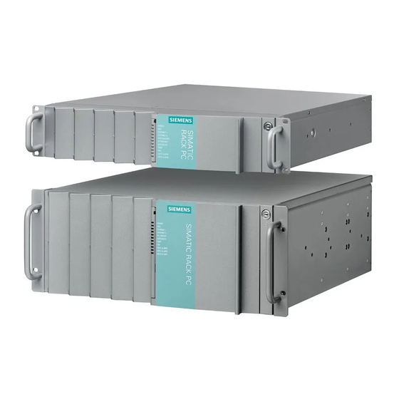
Description External structure Front view of the device (example) Item Description ① Front panel with vent openings (filter mat and fan behind the front panel). Check the filter mat regularly for soiling and, if appropriate, replace it. ② Status displays ③... -
Page 8: Operator Controls
Description 2.2 Operator Controls Operator Controls WARNING The on/off button signal does not cut off power to the PC! CAUTION Data may be lost when the PC performs a hardware reset. Control elements line side switch, On/Off button and Reset button Item Description ①... - Page 9 Description 2.2 Operator Controls Control elements line side switch, On/Off button and Reset button Item Description ③ On/Off switch Used to connect the device to the mains. Depending on the BIOS set-up entry "After Power Failure" the PC switches on ①...
-
Page 10: Connecting Elements
Description 2.3 Connecting elements Connecting elements Interfaces Layout of the interfaces on the rear of the device SIMATIC IPC847C Getting Started, 12/2010, A5E02669190-02... - Page 11 Description 2.3 Connecting elements Layout of the interfaces on the rear of the device Item Designation Description ① PROFIBUS/MPI PROFIBUS interface (RS 485, electrically isolated), 9-pin D-sub socket (optional product characteristic) PROFINET CP-1616 onboard interface, three RJ45 sockets (optional product version) ②...
- Page 12 Description 2.3 Connecting elements Power supply Position of the connector for cooling devices Description ③ Connector for cooling devices of the AC power supply to the device. The permitted power range is 100 VAC to 240 VAC. ③ Connector for cooling devices redundant power supply for the AC power supply of the device.
-
Page 13: Status Displays
Description 2.4 Status displays Status displays Front status displays Display Meaning LEDs Description POWER PC status display isolated from mains YELLOW Standby (hibernating) GREEN PC in operation Display for hard disk no access access GREEN Access No connection ETHERNET 1 * ETHERNET status ... - Page 14 Description 2.4 Status displays Front status displays PN Ι MPI/DP Display of the No connection (optional) communication status No data traffic to S7 or PROFIBUS PROFIBUS not equipped MPI/DP data traffic GREEN No connection Status display for ...
- Page 15 Description 2.4 Status displays Rear status displays Display Meaning Description No cable connected Ethernet LAN 1, 2 * Green LED Link status display Cable disabled Interface disabled, 10 MBit cable active GREEN 100 MBit cable active ORANGE 1000 MBit cable active No cable connected Yellow LED...
- Page 16 Description 2.4 Status displays SIMATIC IPC847C Getting Started, 12/2010, A5E02669190-02...
-
Page 17: Application Planning
● Verify that the shipment contains the complete unit and your separately ordered accessories. Please inform your local dealer of any disagreements or transport damage. ● Please inform Siemens AG by means of the enclosed SIMATIC IPC/PG quality control report form. - Page 18 Application planning 3.2 Unpacking and checking the delivery unit Noting down the device identification data The device can be clearly identified with the help of this identification data in case of repairs or theft. Enter the following data in the table below: ●...
-
Page 19: Ambient And Environmental Conditions
Application planning 3.3 Ambient and environmental conditions Ambient and environmental conditions WARNING If the following requirements for system installation are not observed, approvals to UL 60950-2, EN 60950-2 are rendered void and there is a risk of overheating and injury. When you plan your project, you should make allowances for: ●... - Page 20 Application planning 3.4 Access protection SIMATIC IPC847C Getting Started, 12/2010, A5E02669190-02...
-
Page 21: Installing
Installing Installing the device Optional installation locations The device can be mounted horizontally or vertically in control desks, switching cabinets and 19" rack systems. Optional mounting methods WARNING Function test while installing the device in machines or systems Following the results of a risk analysis, additional protection equipment on the machine or the system is necessary to avoid endangering persons. -
Page 22: Technical Data Of The Telescopic Rails
Installing 4.2 Technical data of the telescopic rails CAUTION The mounting screws of the telescopic rails may not protrude more than 5 mm into the enclosure. CAUTION Risk of injury! It is not permitted to install the device only on the 19-inch brackets of the front panel. Note For vertical operation, install the device on a horizontal metal base and secure it against tilting. -
Page 23: Connection
Connection Connecting peripherals Note before connecting NOTICE Connect only peripherals approved for industrial applications according to EN 61000-6-2. Shielded interface cables must be used for interfaces integrated ex factory. Note Hot-plug I/O modules (USB) may be connected while the PC is in operation. CAUTION I/O devices that are incapable of hot-plugging may only be connected after the device has been disconnected from the power supply. -
Page 24: Connecting The Device To Power
Connection 5.2 Connecting the device to power Connecting the device to power Note before connecting WARNING Do not connect or disconnect power and data cables during thunderstorms. WARNING The device may only be operated on grounded power supply networks (TN systems to VDE 0100, part 300, or IEC 60364-3). - Page 25 Connection 5.2 Connecting the device to power Localized information Outside of the USA and Canada, operation on a 230 V power supply: This device is equipped with a safety-tested power cord which may only be connected to a grounded shockproof power outlet. If you choose not to use this cable, you must use a flexible cable of the following type: Min.
- Page 26 Connection 5.2 Connecting the device to power Connecting Steps for connecting the device to mains ② Ensure that the ON/OFF switch is in "0" position (Off) when you plug in the power cord to avoid unintentional startup of the device. Plug in the connector of the cooling device ①...
- Page 27 Connection 5.2 Connecting the device to power Secure the power plug You can secure the power plug in order to avoid unintentional disconnection of the power cord. Steps for securing the power plug Screw out the lower left-hand fixing screw ②...
-
Page 28: Equipotential Bonding
Connection 5.3 Equipotential bonding Connecting to the redundant power supply Steps for connecting the device to mains (redundant power supply) Connect the two connectors for cooling ① devices Switch both On/Off switches on or off simultaneously. The LED at the power ③... -
Page 29: Strain Relief For Network Cables
Connection 5.4 Strain relief for network cables Strain relief for network cables The strain relief provided in the scope of delivery is used to prevent accidental loosening of the network cable from the device. One cable tie (not included in the package) is required for each interface. - Page 30 Connection 5.4 Strain relief for network cables SIMATIC IPC847C Getting Started, 12/2010, A5E02669190-02...
-
Page 31: Commissioning
Commissioning Requirements for commissioning CAUTION Risk of damage to the device! Make sufficient allowances for the device to acquire room temperature before you put it into use. If condensation has developed on the device wait at least 12 hours before you switch it Note Switching the device on The device is equipped with a power supply unit with line side switch. -
Page 32: Initial Commissioning - Initial Startup
Commissioning 6.2 Initial Commissioning - Initial Startup Initial Commissioning - Initial Startup The Rack PC operating system is automatically set up the first time you switch on the device. Procedure: 1. Press the on/off button. The green power LED lights up. The PC performs a POST. During the self-test, this message appears: Press <F2>... -
Page 33: Reinstalling The Software
Commissioning 6.3 Reinstalling the software Reinstalling the software General installation procedure In case of errors in your software installation, you can reinstall your software using the Recovery CD or DVD, the Documentation and Drivers CD or the Restore DVD. ● Recovery CD or DVD: The recovery CD/DVD contains the Windows user interface with tools for configuring the hard drives, and for installation of the operating system and the languages supported by the operating system (MUI). - Page 34 Commissioning 6.3 Reinstalling the software SIMATIC IPC847C Getting Started, 12/2010, A5E02669190-02...
-
Page 35: Troubleshooting
Troubleshooting General problems This chapter provides you with tips on how to localize and troubleshoot frequently occurring problems. Problem Possible cause To correct or avoid error The device is not operational No power supply Check the power supply, and the power cord / connector Check the environment conditions Device operation is non-compliant... - Page 36 Troubleshooting 7.1 General problems Problem Possible cause To correct or avoid error USB device not responding. The USB ports are disabled in Use a different USB port or enable the port. BIOS. USB 2.0 device connected and Enable USB 2.0. USB 2.0 is disabled.
- Page 37 Troubleshooting 7.1 General problems Error displays on the front panel Front LED Possible cause For details about the error display, see the operating instructions: Red WATCHDOG LED is lit Watchdog has triggered Section "Watchdog (WD)" Red TEMP LED is lit Excess temperature in the device Section "Temperature monitoring / display Red FAN LED is lit...
- Page 38 Troubleshooting 7.1 General problems SIMATIC IPC847C Getting Started, 12/2010, A5E02669190-02...
-
Page 39: Dimension Drawings
Dimension drawings Dimensional drawing of the device SIEMENS POWER ETHERNET 1 ETHERNET 2 PROFIBUS/MPI WATCHDOG TEMP HDD1 ALARM HDD2 ALARM Figure 8-1 Dimensional drawing SIMATIC IPC847C Getting Started, 12/2010, A5E02669190-02... -
Page 40: Dimensional Drawing For The Use Of Telescopic Rails
Dimension drawings 8.2 Dimensional drawing for the use of telescopic rails Dimensional drawing for the use of telescopic rails Figure 8-2 Dimensional drawing for the use of telescopic rails SIMATIC IPC847C Getting Started, 12/2010, A5E02669190-02... -
Page 41: Appendix
Appendix Guidelines and declarations Notes on CE marking The following applies to the SIMATIC product described in this documentation: EMC directive This product meets the requirements of EC directive 2004/108/EEC "Electromagnetic Compatibility", and is designed for operation in the following fields of application in accordance with this CE marking: Fields of application Requirement for... -
Page 42: Certificates And Approvals
Peripheral devices are only be connected via shielded cables. Certificates and Approvals ISO 9001 certificate The Siemens quality management system for all production processes (development, production and sales) meets ISO 9001:2000 requirements. This has been certified by DQS (the German society for the certification of quality management systems). - Page 43 Appendix A.2 Certificates and Approvals Federal Communications This equipment has been tested and found to comply with the limits for a Commission Class A digital device, pursuant to Part 15 of the FCC Rules. These limits are designed to provide reasonable protection against harmful Radio Frequency interference when the equipment is operated in a commercial Interference Statement...
-
Page 44: Service And Support
Industry Automation and Drive Technologies - Homepage (http://www.siemens.com/automation/service&support) After-sales information system for SIMATIC PC / PG Information about contacts, drivers, and BIOS updates, FAQs and Customer Support can be found at: After-sales information system for SIMATIC PC/PG (http://www.siemens.com/asis) SIMATIC IPC847C Getting Started, 12/2010, A5E02669190-02... -
Page 45: Index
Index Front door, 7 Front view, 7 Angle brackets Mounting methods, 21 Approvals, 19, 42 I/O devices, 23 Identification data, 18 Initial commissioning, 32 installation Installation locations, 21 CE marking, 41 Mounting methods, 21 Certificates, 42 Interfaces, 10 Connecting COM, 11 Peripherals, 42 DVI-D, 11 Power supply, 24... - Page 46 Index Operating system, 31 Initial commissioning, 32 Ventilation slots, 19 Order no., 18 WATCHDOG, 14 Peripherals Connecting, 42 Power LED, 32 Power supply, 24 Power supply Connecting, 2424 PROFIBUS/MPI, 11 Protection class, 19 Rating plate, 7 Rear view, 7 Reset button, 7, 8 Restart, 32 Secure the power plug, 27 Serial number:, 18...