Table of Contents
Advertisement
Quick Links
SIMATIC NET
Industrial Remote Communication -
TeleControl
SINAUT ST7 station control system
System Manual
Volume 1: System and Hardware
09/2016
C79000-G8976-C178-10
___________________
Preface
Properties of the SINAUT
___________________
components
Network structures and
___________________
topologies
___________________
Installation guide
Installing and putting a TIM
___________________
into operation
Installation and
commissioning of the
modems and routers
___________________
Technical specifications
___________________
Certifications and approvals
___________________
References
1
2
3
4
5
6
7
A
Advertisement
Table of Contents

Related Manuals for Siemens SIMATIC NET TeleControl SINAUT ST7


Summary of Contents for Siemens SIMATIC NET TeleControl SINAUT ST7
- Page 1 ___________________ Preface Properties of the SINAUT ___________________ components Network structures and ___________________ SIMATIC NET topologies ___________________ Installation guide Industrial Remote Communication - TeleControl Installing and putting a TIM ___________________ into operation SINAUT ST7 station control system Installation and commissioning of the System Manual modems and routers ___________________...
- Page 2 Note the following: WARNING Siemens products may only be used for the applications described in the catalog and in the relevant technical documentation. If products and components from other manufacturers are used, these must be recommended or approved by Siemens. Proper transport, storage, installation, assembly, commissioning, operation and maintenance are required to ensure that the products operate safely and without any problems.
-
Page 3: Preface
• Accessories: Overvoltage protection module as replacement part for LTOP1 and LTOP2, DIN rail adapter, various plug-in cables Observe the product notifications on the Internet: Link: (https://support.industry.siemens.com/cs/ww/en/ps/15915/pm) • EGPRS router MD741-1 Observe the following product notification: Link: (https://support.industry.siemens.com/cs/ww/en/view/62607452) If there are successors to the discontinued devices, you will find these in the notifications listed above on the Internet. - Page 4 Preface To upgrade to this version, a full version of the SINAUT engineering software V5.0 must be installed. The engineering software V5.5 SP2 can be used with STEP 7 as of version V5.4 SP4. To use the engineering software, a Windows operating system is required that is compatible with the installed STEP 7 version.
- Page 5 • TIM 4V, TIM 4VD, TIM 42, TIM 42D, TIM 43, TIM 43D, TIM 44, TIM 44D If you require information on these modules or on SINAUT ST1, refer to release 05/2007 of this manual. You will find release 05/2007 on the Internet pages of Siemens Industry Online Support at the following address: Link: (https://support.industry.siemens.com/cs/ww/en/ps/15931/man)
- Page 6 Siemens’ products and solutions undergo continuous development to make them more secure. Siemens strongly recommends to apply product updates as soon as available and to always use the latest product versions. Use of product versions that are no longer supported, and failure to apply latest updates may increase customer’s exposure to cyber threats.
- Page 7 Trademarks The following and possibly other names not identified by the registered trademark sign ® registered trademarks of Siemens AG: SINAUT, TIM, SCALANCE, MODEM MD720, MD741-1, Modem MD2 / MD3 / MD4, LTOP Version history The previous versions of the manual described the innovations and versions listed below.
- Page 8 Preface Validity of the manual: ● SINAUT ST7 configuration and diagnostics software for the PG V5.2 ● SINAUT TD7 library for the CPU V2.2 SP2 ● SINAUT TIM firmware V4.4.0 for the TIM 4 ● SINAUT TIM firmware V2.3 for the TIM 3V-IE variants ●...
- Page 9 Preface Validity of the manual: ● SINAUT ST7 configuration software for the PG/PC V4.1 ● SINAUT TD7 library for the CPU V2.2 ● SINAUT TIM firmware V4.3.7 for the TIM 3 / TIM 4 ● SINAUT TIM firmware V1.2 for the TIM 3V-IE variants ●...
-
Page 10: System Manual, 09/2016, C79000-G8976-C178
Preface SINAUT ST7 station control system System Manual, 09/2016, C79000-G8976-C178-10... -
Page 11: Table Of Contents
Table of contents Preface ..............................3 Properties of the SINAUT components ....................15 Area of application ........................15 Components in a SINAUT ST7 system .................. 16 Properties of the TIM modules ....................17 1.3.1 Overview of All TIM Variants ....................19 1.3.2 TIM 3V-IE / TIM 3V-IE Advanced ................... - Page 12 Table of contents 1.7.1 Variants and overview of the LTOP overvoltage protection modules ........64 Connecting cables ......................... 65 1.8.1 Cable for connecting TIM and modem modules ..............66 1.8.2 Cables for the WAN connection of the modems ..............67 1.8.3 TIM 4R / 4RD interface adapter cable ...................
- Page 13 Table of contents GSM/GPRS modem MD720-3 ....................143 5.3.1 Displays and connectors ....................... 144 5.3.2 Connecting the MD720-3 to the TIM and antenna ............... 147 5.3.3 Prerequisites for operation ....................148 GPRS/GSM router MD741-1 ....................148 5.4.1 Displays and connectors ....................... 149 5.4.2 Connecting the MD741-1 to the TIM and antenna ...............
- Page 14 Table of contents Approvals for the TIM 4R/4RD and the SINAUT modems ..........259 Additional approvals for SINAUT products for the analog telephone network ....262 Approvals for the TIM 3V-IE variants and the TIM 4R-IE ............ 265 References ............................271 Glossary ..............................
-
Page 15: Properties Of The Sinaut Components
Properties of the SINAUT components Area of application Process control over WAN and Ethernet SINAUT ST7 is a system based on SIMATIC S7 for fully automatic monitoring and control ® ® of process stations that exchange data with another and with one or more control centers over a WAN (wide area network) or Ethernet (TCP/IP). -
Page 16: Components In A Sinaut St7 System
Properties of the SINAUT components 1.2 Components in a SINAUT ST7 system SINAUT over Ethernet SINAUT communication is possible between station and control center and between stations over Ethernet or IP-based networks. This includes transmission using the GPRS service in mobile wireless networks (GSM networks). -
Page 17: Properties Of The Tim Modules
Properties of the SINAUT components 1.3 Properties of the TIM modules Hardware components The range of hardware components includes: ● TIM communications modules ● MD modem modules Classic modems for dedicated line, analog and ISDN dial-up networks ● Mobile wireless components e.g. - Page 18 Properties of the SINAUT components 1.3 Properties of the TIM modules TIM 3V-IE / TIM 3V-IE Advanced The TIM 3V-IE is a SINAUT communications module for the SIMATIC S7-300. It has an RS- 232 interface to which a suitable modem can be connected. It also has an RJ-45 interface that allows SINAUT communication over IP-based networks (LAN or WAN).
-
Page 19: Overview Of All Tim Variants
Properties of the SINAUT components 1.3 Properties of the TIM modules 1.3.1 Overview of All TIM Variants All TIMs are supplied with a bus module connector allowing the TIM to be installed in an S7-300 as a CP. The adapter cable for the second RS-232/RS-485 port ships with the TIM 4R variant. - Page 20 Properties of the SINAUT components 1.3 Properties of the TIM modules ● It has two interfaces: – RS-232 interface for connection of required WAN transmission equipment (classic SINAUT WAN) To allow use of GPRS, the switchable serial interface of a station TIM 3V-IE can be connected to a GSM network via the GSM modem MD720-3.
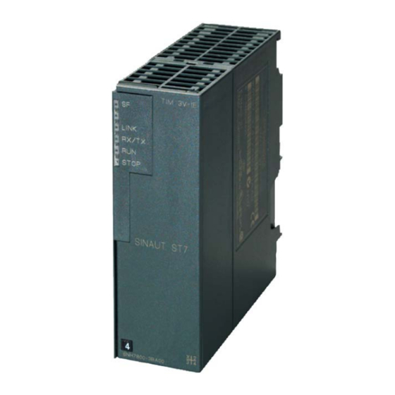
- Page 21 Properties of the SINAUT components 1.3 Properties of the TIM modules Figure 1-1 SINAUT TIM 3V-IE communications module The TIM 3V-IE variants have all the advantages of the SIMATIC S7-300 system design: ● Compact design; single standard width of the SM modules of the SIMATIC S7-300 ●...
-
Page 22: Front View Of The Tim 3V-Ie Variants With Closed Front Panel
Properties of the SINAUT components 1.3 Properties of the TIM modules Figure 1-2 Connectors of the TIM 3V-IE or TIM 3V-IE Advanced 1.3.2.2 Front view of the TIM 3V-IE variants with closed front panel Figure 1-3 Front view of a TIM 3V-IE variant with closed front panel SINAUT ST7 station control system System Manual, 09/2016, C79000-G8976-C178-10... -
Page 23: Front View Of The Tim 3V-Ie Variants With Front Panel Removed
Properties of the SINAUT components 1.3 Properties of the TIM modules 1.3.2.3 Front view of the TIM 3V-IE variants with front panel removed Figure 1-4 Front view of a TIM 3V-IE variant with front panel removed For information on the RESET button, refer to "Default startup" in the section "Startup activities of the TIM 3V-IE variants". - Page 24 Properties of the SINAUT components 1.3 Properties of the TIM modules LED no. Labeling Relevant TIM inter- Description face LINK Ethernet Connection to Ethernet LED is lit if there is a physical connection to Ethernet. LED is off if there is no physical connection to Ethernet. RX/TX Ethernet Data flow over Ethernet...
-
Page 25: Pinout Of The Ports
Properties of the SINAUT components 1.3 Properties of the TIM modules 1.3.2.5 Pinout of the ports RS-232 interface The connector for the RS-232 port is designed as a 9-pin D-sub miniature connector (male). The pinout is shown in the following table. As an RS-232 port, the pinout corresponds to that of a standardized PC connector. - Page 26 Properties of the SINAUT components 1.3 Properties of the TIM modules Table 1- 6 Standard connecting cables for the RS-232 port of the TIM 3V-IE variants Order no. Description Illustration 6NH7701-4AL Cable for connecting the TIM 3V-IE (RS-232) to one of the SINAUT ST7 modems MD2, MD3 or MD4 (RS-232).
- Page 27 Properties of the SINAUT components 1.3 Properties of the TIM modules Figure 1-5 Assembly of the standard connecting cable 6NH7701-4AL Figure 1-6 Assembly of the standard connecting cable 6NH7701-5AN SINAUT ST7 station control system System Manual, 09/2016, C79000-G8976-C178-10...
- Page 28 Properties of the SINAUT components 1.3 Properties of the TIM modules Figure 1-7 Assembly of the standard connecting cable 6NH7701-4BN Figure 1-8 Assembly of the standard connecting cable 6NH7701-0AR Connecting cables for connecting to Ethernet There is no standard connecting cable available in the SINAUT range to connect the TIM 4R-IE to Ethernet.
-
Page 29: Tim 4R-Ie
Properties of the SINAUT components 1.3 Properties of the TIM modules Figure 1-9 Pinout of a crossover Ethernet RJ-45 cable The cable must be suitable for the 10Base-TX or 100Base-TX specification. 1.3.3 TIM 4R-IE 1.3.3.1 The TIM 4R-IE ● TIM without integrated modem, double width ●... -
Page 30: Design Of The Tim 4R-Ie
Properties of the SINAUT components 1.3 Properties of the TIM modules ● The four transmission paths can all be different and operated independently. The two pairs of interfaces can also form a redundant transmission path. ● When installed as a CP in an S7-300, the following communication is also possible: –... - Page 31 Properties of the SINAUT components 1.3 Properties of the TIM modules ● Two RJ-45 jacks for connection to Ethernet; industrial design with additional collar for inserting the IE FC RJ-45 Plug 180 ● 2-pin plug-in terminal block for connecting the external supply voltage of 24 V DC ●...
-
Page 32: Front View Of The Tim 4R-Ie With Closed Front Panel
Properties of the SINAUT components 1.3 Properties of the TIM modules 1.3.3.3 Front view of the TIM 4R-IE with closed front panel Figure 1-12 Front view of the TIM 4R-IE with closed front panel For information on the RESET button, refer to "Default startup" in the section Startup activities of the TIM 4R-IE (Page 136). -
Page 33: Front View Of The Tim 4R-Ie With Removed Front Panel
Properties of the SINAUT components 1.3 Properties of the TIM modules 1.3.3.4 Front view of the TIM 4R-IE with removed front panel Figure 1-13 Front view of the TIM 4R-IE with removed front panel On the rear of the housing, there is an opening for the optional C-PLUG. The configuration data of the TIM 4R-IE can be stored on the C-PLUG. -
Page 34: Leds Of The Tim 4R-Ie
Properties of the SINAUT components 1.3 Properties of the TIM modules 1.3.3.5 LEDs of the TIM 4R-IE The following table summarizes the meaning of the LEDs during normal operation. The display during startup is explained in the section "Startup activities of the TIM 4R-IE (Page 136)". -
Page 35: Pinout Of The Ports
Properties of the SINAUT components 1.3 Properties of the TIM modules LED no. Labeling Relevant TIM port Type of WAN Description driver RXD2 RS-232 interface 2 Dedicated line Receive data As long as receive level (DCD) is detected, the LED is lit and goes off while a message is being received (RXD). -
Page 36: Standard Connecting Cables For The Tim 4R-Ie
Properties of the SINAUT components 1.3 Properties of the TIM modules This is a combined RS-232/RS-485 port. As default, the ports are set to RS-232. The switchover to RS-485 is set in the SINAUT configuration in NetPro and is therefore part of the configuration data of the TIM 4R-IE. - Page 37 Properties of the SINAUT components 1.3 Properties of the TIM modules Table 1- 11 Standard connecting cables for the serial port of the TIM 4R-IE Order no. Description Illustration 6NH7701-4AL Cable for connecting the TIM 3V-IE (RS-232) to one of the SINAUT ST7 modems MD2, MD3 or MD4 (RS-232).
- Page 38 Properties of the SINAUT components 1.3 Properties of the TIM modules Figure 1-14 Assembly of the standard connecting cable 6NH7701-4AL Figure 1-15 Assembly of the standard connecting cable 6NH7701-4DL SINAUT ST7 station control system System Manual, 09/2016, C79000-G8976-C178-10...
- Page 39 Properties of the SINAUT components 1.3 Properties of the TIM modules Figure 1-16 Assembly of the standard connecting cable 6NH7701-5AN Figure 1-17 Assembly of the standard connecting cable 6NH7701-4BN SINAUT ST7 station control system System Manual, 09/2016, C79000-G8976-C178-10...
- Page 40 Properties of the SINAUT components 1.3 Properties of the TIM modules Figure 1-18 Assembly of the standard connecting cable 6NH7701-0AR Connecting cables for connecting to Ethernet There is no standard connecting cable available in the SINAUT range to connect the TIM 4R-IE to Ethernet.
-
Page 41: Tim 4 / Tim 4Rd
Properties of the SINAUT components 1.3 Properties of the TIM modules 1.3.4 TIM 4 / TIM 4RD 1.3.4.1 The TIM 4 variants There are two variants of the TIM 4, the TIM 4R and TIM 4RD. They do not have an integrated modem but have two combined RS-232/RS-485 ports to connect to a WAN. - Page 42 Properties of the SINAUT components 1.3 Properties of the TIM modules Figure 1-20 SINAUT TIM 4 communications module The following figure shows the ports of the two TIM 4R variants (schematic representation with covers removed). Figure 1-21 Ports of the TIM 4R SINAUT ST7 station control system System Manual, 09/2016, C79000-G8976-C178-10...
-
Page 43: Design Of The Tim 4 Variants
Properties of the SINAUT components 1.3 Properties of the TIM modules 1.3.4.2 Design of the TIM 4 variants The TIM 4 types have all the advantages of the SIMATIC S7-300 system design: ● Compact design; double standard width of the SM modules of the SIMATIC S7-300 ●... -
Page 44: Front View Of The Tim 4 With Closed Front Panels
Properties of the SINAUT components 1.3 Properties of the TIM modules 1.3.4.3 Front view of the TIM 4 with closed front panels Figure 1-22 Front view of the TIM with closed front panels SINAUT ST7 station control system System Manual, 09/2016, C79000-G8976-C178-10... -
Page 45: Front View Of The Tim 4 With Removed Front Panels
Properties of the SINAUT components 1.3 Properties of the TIM modules 1.3.4.4 Front view of the TIM 4 with removed front panels Figure 1-23 Front view of the TIM with removed front panels For information on the RESET button, refer to "Default startup" in the section "Startup activities of the TIM 4". -
Page 46: Leds Of The Tim 3 / Tim 4
Properties of the SINAUT components 1.3 Properties of the TIM modules 1.3.4.5 LEDs of the TIM 3 / TIM 4 The following table summarizes the meaning of the six LEDs during normal operation. The display during startup is explained in the section "Startup activities of the TIM 3 and TIM 4 (Page 138)". - Page 47 Properties of the SINAUT components 1.3 Properties of the TIM modules The connector can be configured either as an RS-232 or as an RS-485 port using the 8-pin DIL switch available from above through the grill in the housing. Table 1- 13 PIN assignment of the X1 connector for connecting and external modem Illustration Pin no.
-
Page 48: Standard Connecting Cables That Can Be Connected To Connector X1
Properties of the SINAUT components 1.3 Properties of the TIM modules 1.3.4.7 Standard connecting cables that can be connected to connector X1 An external modem or other transmission device can be connected to the 9-pin X1 connector of the combined RS-232/RS-485 interface. To connect to connector X1, the following standard connecting cables are available. - Page 49 Properties of the SINAUT components 1.3 Properties of the TIM modules Order no. Description Illustration 6NH7701-4BN Cable with one end without connector for connecting the TIM (RS-232) to a third-party modem or wireless device (RS-232) Cable length 2.5 m 6NH7701-0AR Test cable.
- Page 50 Properties of the SINAUT components 1.3 Properties of the TIM modules Figure 1-25 Assembly of the standard connecting cable 6NH7701-4DL Figure 1-26 Assembly of the standard connecting cable 6NH7701-5AN SINAUT ST7 station control system System Manual, 09/2016, C79000-G8976-C178-10...
- Page 51 Properties of the SINAUT components 1.3 Properties of the TIM modules Figure 1-27 Assembly of the standard connecting cable 6NH7701-4BN Figure 1-28 Assembly of the standard connecting cable 6NH7701-0AR SINAUT ST7 station control system System Manual, 09/2016, C79000-G8976-C178-10...
-
Page 52: View Of The Tim 4 From Above
Properties of the SINAUT components 1.3 Properties of the TIM modules 1.3.4.8 View of the TIM 4 from above Figure 1-29 View of the TIM from above SINAUT ST7 station control system System Manual, 09/2016, C79000-G8976-C178-10... -
Page 53: View Of The Tim 3 / Tim 4 From Below
Properties of the SINAUT components 1.3 Properties of the TIM modules 1.3.4.9 View of the TIM 3 / TIM 4 from below Figure 1-30 View of the TIM from below DCF77 adapter cable An adapter cable is required to connect the integrated DCF77 radio clock to an indoor or outdoor antenna. - Page 54 Properties of the SINAUT components 1.3 Properties of the TIM modules The adapter cable is supplied with every TIM module with an integrated DCF77 radio clock. It can also be ordered as a spare part under the number listed in the following table. Table 1- 16 Adapter cable for a TIM 4 with integrated DCF77 radio clock Order no.
-
Page 55: The Classic Sinaut St7 Modems
Properties of the SINAUT components 1.4 The classic SINAUT ST7 modems The classic SINAUT ST7 modems The SINAUT ST7 modems MD2, MD3 and MD4 are fitted into an S7-300 housing like the TIM modules. Figure 1-31 SINAUT MD modem 1.4.1 The modem variants The following modem variants are available: Dedicated line modem... -
Page 56: Overview Of The Modems Md2, Md3, Md4 And Accessories
Properties of the SINAUT components 1.4 The classic SINAUT ST7 modems Due to their design, the modems can be installed on an S7-300 standard rail just like the TIM modules. As an alternative, the modems can also be installed on a 35 mm standard mounting rail. -
Page 57: Mobile Wireless Components
Properties of the SINAUT components 1.5 Mobile wireless components Mobile wireless components 1.5.1 Areas of application Options for data transmission via mobile wireless with SINAUT Wherever no other transmission medium such as a dedicated line or telephone network is available and where the setting up of a separate wireless network would involve high costs, data transmission using a mobile wireless network is a practical alternative. -
Page 58: Antennas
The antennas must be ordered separately. ● Quadband antenna ANT794-4MR You will find detailed information in the device manual. You will find this on the Internet on the pages of Siemens Industrial Automation Customer Support under the following entry 16518558 (http://support.automation.siemens.com/WW/view/en/16518558) Figure 1-33... -
Page 59: Radio Clock Components
Properties of the SINAUT components 1.6 Radio clock components Radio clock components 1.6.1 Accessories for DCF77 Adapter cable for DCF77 radio clock of the TIM 4R D An adapter cable is required to connect the DCF77 radio clock to an indoor or outdoor antenna. - Page 60 Properties of the SINAUT components 1.6 Radio clock components DCF77 outdoor antenna for flat roof, wall or mast installation Whenever possible, a professional radio clock system should use an outdoor antenna. In contrast to an indoor antenna whose environment can change constantly due to the technical activity in the building, the conditions for an outdoor antenna are practically constant.
-
Page 61: Gps Receiver
Properties of the SINAUT components 1.6 Radio clock components Figure 1-36 Connecting DCF77 antennas 1.6.2 GPS receiver The reception of the DCF77 radio clock signal is limited to western Europe (approximately 800 km radius from Frankfurt am Main, Germany). In regions where this signal cannot be received, a GPS receiver can be used to acquire the local time from a satellite-based GPS system (Global Positioning System). - Page 62 Properties of the SINAUT components 1.6 Radio clock components Since the GPS antenna is an outdoor antenna, you should also install the available lightning protection device. Figure 1-37 The GPS receiver module (left) and the recommended lightning protection device for outdoor antennas (right) The following figure shows the interconnection of the various GPS components (the adapter cable 6NH7700-0AD15 is supplied with each TIM with an integrated DCF77 radio clock...
-
Page 63: Overview Of The Radio Clock Components
Properties of the SINAUT components 1.6 Radio clock components Figure 1-38 GPS components for receiving the radio clock signal 1.6.3 Overview of the radio clock components The following table shows the accessories for the DCF77 radio clock of the TIM. Table 1- 20 Overview of the accessories for the DCF77 radio clock of the TIM Short name... -
Page 64: Ltop Overvoltage Protection Modules
Properties of the SINAUT components 1.7 LTOP overvoltage protection modules Short name Order no. Explanation GPS-Kit 6NH9831-8AA GPS complete package for simulating the DCF77 time signal, consisting of GPS receiver, GPS outdoor antenna including 25 m cable, BNC adapter connector, configuration software, PC adapter cable, and documentation. -
Page 65: Connecting Cables
Properties of the SINAUT components 1.8 Connecting cables LTOP2 Overvoltage protection module for use at the start or end of a 4-wire dedicated line or in a 2- wire tapping point. In a 4-wire tapping point, two LTOP2 modules are required. Table 1- 21 Overview of the LTOP modules Short name... -
Page 66: Cable For Connecting Tim And Modem Modules
Properties of the SINAUT components 1.8 Connecting cables 1.8.1 Cable for connecting TIM and modem modules Table 1- 22 Standard cables for connecting TIM and modem modules Order no. Description Illustration 6NH7701-4AL Cable for connecting a TIM 3V-IE / TIM 4 (RS-232) with one of the SINAUT ST7 MD2, MD3 or MD4 modems (RS-232). -
Page 67: Cables For The Wan Connection Of The Modems
Properties of the SINAUT components 1.8 Connecting cables Order no. Description Illustration 6NH1701-7AN Cable for connecting a TIM 11 (RS-232) with one of the SINAUT ST7 MD2, MD3 or MD4 modems (RS-232). Cable length 2.5 m 6NH1701-7BK Cable for connecting a TIM011B (RS-232) with one of the SINAUT ST7 MD2, MD3 or MD4 modems (RS-232). -
Page 68: Tim 4R / 4Rd Interface Adapter Cable
Properties of the SINAUT components 1.9 SINAUT ST7cc, the add-on for WinCC 1.8.3 TIM 4R / 4RD interface adapter cable The TIM 4R / TIM 4RD has a second serial interface X3 (combined RS-232/RS-485). The interface (8-pin RJ-45 jack) is accessible from below. An adapter cable is required to connect the second serial port with an external modem or other transmission device. -
Page 69: The Special Properties Of Sinaut St7Cc
Properties of the SINAUT components 1.9 SINAUT ST7cc, the add-on for WinCC Figure 1-40 SINAUT ST7cc control center system (single or redundant) with attached SINAUT stations Note The SINAUT ST7cc for WinCC expansion packet is described in detail in a separate manual. To complete the "Introduction to the SINAUT ST7 system"... - Page 70 Properties of the SINAUT components 1.9 SINAUT ST7cc, the add-on for WinCC ● General request to affected stations following data transfer problems to allow the process image to be updated in ST7cc ● For diagnostic purposes: Selective recording of message traffic for individual or all SINAUT subscribers.
-
Page 71: Sinaut St7Sc Scada Connect Software
Properties of the SINAUT components 1.10 SINAUT ST7sc SCADA Connect software 1.10 SINAUT ST7sc SCADA Connect software The SINAUT system allows the networking of SIMATIC stations with a control center over a classic or IP-based WAN (Wide Area Network). This control center can also be a SIMATIC station or a PC-based control center, for example, WinCC with the SINAUT ST7cc add-on. -
Page 72: The Special Properties Of Sinaut St7Sc
Properties of the SINAUT components 1.10 SINAUT ST7sc SCADA Connect software 1.10.1 The special properties of SINAUT ST7sc Acquisition of the process data The SINAUT station acquires the process data when it changes and transfers it via the WAN to SINAUT ST7sc. There the received SINAUT messages are decoded and stored in the ST7sc tag management according to the configuration. - Page 73 Properties of the SINAUT components 1.10 SINAUT ST7sc SCADA Connect software Figure 1-42 System configuration with SINAUT ST7sc Redundant application SINAUT ST7sc also allows the connection of a redundant client system. In this case, two ST7sc systems would need to be used. They transfer data received from the stations to both clients in parallel and independently of each other and accept data from them that needs to be sent to the stations.
- Page 74 Properties of the SINAUT components 1.10 SINAUT ST7sc SCADA Connect software SINAUT ST7 station control system System Manual, 09/2016, C79000-G8976-C178-10...
-
Page 75: Network Structures And Topologies
Network structures and topologies The following overview shows you the network structures that can be implemented with SINAUT ST7 in a WAN and on Industrial Ethernet. For each network configuration, you will also see the protocols and modes with which SINAUT can handle communication over the network. -
Page 76: Configurations
Network structures and topologies 2.2 Configurations Configurations The symbols used in the following configurations represent the various modules with their LAN or WAN interfaces. Note Notes on TIM 4 / TIM 4R-IE • The two WAN interfaces of a TIM 4R / TIM 4RD can both have the same function (for example 2 x master) or different functions (for example node + master). - Page 77 Network structures and topologies 2.2 Configurations Wireless Ethernet communication Figure 2-2 Wireless Ethernet communication Wireless Ethernet communication with TIM 3V-IE in master stations and stations Figure 2-3 Wireless Ethernet communication with TIM 3V-IE in master stations and stations SINAUT ST7 station control system System Manual, 09/2016, C79000-G8976-C178-10...
- Page 78 Network structures and topologies 2.2 Configurations IP-based communication via DSL Figure 2-4 IP-based communication via DSL SINAUT ST7 station control system System Manual, 09/2016, C79000-G8976-C178-10...
- Page 79 Network structures and topologies 2.2 Configurations IP-based communication via GPRS with simple security (simple Internet communication) Figure 2-5 IP-based communication (GPRS/DSL) with MSC protocol via MD720 modem SINAUT ST7 station control system System Manual, 09/2016, C79000-G8976-C178-10...
- Page 80 Network structures and topologies 2.2 Configurations IP-based communication via GPRS with higher security Figure 2-6 GPRS with higher security via SCALANCE M874 router SINAUT ST7 station control system System Manual, 09/2016, C79000-G8976-C178-10...
-
Page 81: Configurations With Classic Wan
Network structures and topologies 2.2 Configurations 2.2.2 Configurations with classic WAN Dedicated line configurations Figure 2-7 Dedicated line configurations SINAUT ST7 station control system System Manual, 09/2016, C79000-G8976-C178-10... - Page 82 Network structures and topologies 2.2 Configurations Radio network configuration Figure 2-8 Radio network configurations SINAUT ST7 station control system System Manual, 09/2016, C79000-G8976-C178-10...
- Page 83 Network structures and topologies 2.2 Configurations Dial-up network configuration Figure 2-9 Dial-up network configurations SINAUT ST7 station control system System Manual, 09/2016, C79000-G8976-C178-10...
- Page 84 Network structures and topologies 2.2 Configurations Examples of redundant configurations Figure 2-10 Redundant configurations For further options for setting up redundant transmission paths, refer to section Installing the TIM 4R-IE in an S7-300 (Page 94). SINAUT ST7 station control system System Manual, 09/2016, C79000-G8976-C178-10...
-
Page 85: Installation Guide
Installation guide Installing the TIM 3V-IE variants in an S7-300 Introduction The TIM 3V-IE variants can be used in an S7-300 as communications processors (CP). In principle, all S7-300 standard and compact CPUs can be combined with these TIMs. There are, however, constraints that must be taken into account relating to the way in which data exchange between the TIM and the CPU in the rack is handled (the SINAUT program). - Page 86 Installation guide 3.1 Installing the TIM 3V-IE variants in an S7-300 Standard CPU type As of article number CPU 314 6ES7 314-1AE02-0AB0 6ES7 314-1AE03-0AB0 6ES7 314-1AE04-0AB0 6ES7 314-1AF10-0AB0 6ES7 314-1AF11-0AB0 6ES7 314-1AG13-0AB0 6ES7 314-1AG14-0AB0 CPU 314 IFM 6ES7 314-5AE02-0AB0 6ES7 314-5AE03-0AB0 6ES7 314-5AE10-0AB0 CPU 315 6ES7 315-1AF01-0AB0...
- Page 87 Installation guide 3.1 Installing the TIM 3V-IE variants in an S7-300 Standard CPU type As of article number CPU 319-3 PN/DP 6ES7 318-3EL00-0AB0 6ES7 318-3EL01-0AB0 CPU 319F-3 PN/DP 6ES7 318-3FL00-0AB0 6ES7 318-3FL01-0AB0 Compact CPU type Article number CPU 312C 6ES7 312-5BD00-0AB0 6ES7 312-5BD01-0AB0 6ES7 312-5BE03-0AB0 6ES7 312-5BF04-0AB0...
- Page 88 Installation guide 3.1 Installing the TIM 3V-IE variants in an S7-300 C7 control systems Article number C7-626/P DP 6ES7 626-2DG02-0AB3 6ES7 626-2DG03-0AE3 6ES7 626-2DG04-0AE3 C7-633/P 6ES7 633-1DF00-0AB3 6ES7 633-1DF02-0AE3 C7-633 DP 6ES7 633-2BF00-0AB3 6ES7 633-2BF01-0AE3 6ES7 633-2BF02-0AE3 C7-634/P 6ES7 634-1DF00-0AB3 6ES7 634-1DF02-0AE3 C7-634 DP 6ES7 634-2BF00-0AB3...
- Page 89 Installation guide 3.1 Installing the TIM 3V-IE variants in an S7-300 If a SINAUT modem of the type MD2, MD3 or MD4 is used, this can be installed on a separate S7-300 rail or on a 35 mm DIN rail (an adapter is available). To save space, it can also be installed in a free slot of racks 0 to 3.
- Page 90 Installation guide 3.1 Installing the TIM 3V-IE variants in an S7-300 S7-300 with access to IP-based WAN To implement IP-based WAN access for an S7-300, you can use either a TIM 3V-IE or a TIM 3V-IE Advanced. Figure 3-2 SIMATIC S7-300 with TIM 3V-IE with 1 connection to IP-based WAN A module is required on the Ethernet interface (RJ-45) of the TIM to link the TIM to an IP- based WAN.
- Page 91 Installation guide 3.1 Installing the TIM 3V-IE variants in an S7-300 Figure 3-4 SIMATIC S7-300 with TIM 3V-IE, 1 GPRS access via MD741-1 router S7-300 with two WAN attachments To achieve two connections to a WAN for an S7-300, in other words, classic WAN access and IP-based access, a TIM 3V-IE Advanced must be used.
- Page 92 Installation guide 3.1 Installing the TIM 3V-IE variants in an S7-300 ST7cc / ST7sc with the TIM 3V-IE Advanced A TIM 3V-IE Advanced can be used as a master TIM for the PC of the ST7cc or ST7sc control center. In this case, the TIM 3V-IE Advanced requires an S7-300 CPU because it cannot work without a CPU.
- Page 93 Installation guide 3.1 Installing the TIM 3V-IE variants in an S7-300 maximum number of TIM modules is restricted by the number of connection resources of the CP in the control center PC. Connection to ST7cc / ST7sc over Ethernet The following figure shows a configuration in which the TIM is connected to the PC over its Ethernet interface.
-
Page 94: Installing The Tim 4R-Ie In An S7-300
Installation guide 3.2 Installing the TIM 4R-IE in an S7-300 Installing the TIM 4R-IE in an S7-300 Introduction The TIM 4R-IE can be used in an S7-300 as a communications processor (CP). All S7-300 standard and compact CPUs can be combined with the TIM 4R-IE. There are, however, constraints that must be taken into account relating to the way in which data exchange between the TIM and the CPU in the rack is handled (the SINAUT program). - Page 95 Installation guide 3.2 Installing the TIM 4R-IE in an S7-300 Standard CPU type As of article number CPU 315-2 DP 6ES7 315-2AF01-0AB0 6ES7 315-2AF02-0AB0 6ES7 315-2AF03-0AB0 6ES7 315-2AG10-0AB0 6ES7 315-2AH14-0AB0 CPU 315-2 PN/DP 6ES7 315-2EG10-0AB0 6ES7 315-2EH13-0AB0 6ES7 315-2EH14-0AB0 CPU 315T-2 DP 6ES7 315-6TG10-0AB0 6ES7 315-6TH13-0AB0 CPU 315T-3 PN/DP...
- Page 96 Installation guide 3.2 Installing the TIM 4R-IE in an S7-300 Compact CPU type Article number CPU 312C 6ES7 312-5BD00-0AB0 6ES7 312-5BD01-0AB0 6ES7 312-5BE03-0AB0 6ES7 312-5BF04-0AB0 CPU 313C 6ES7 313-5BE00-0AB0 6ES7 313-5BE01-0AB0 6ES7 313-5BF03-0AB0 6ES7 313-5BG04-0AB0 CPU 313C-2 PtP 6ES7 313-6BE00-0AB0 6ES7 313-6BE01-0AB0 6ES7 313-6BF02-0AB0 6ES7 313-6BF03-0AB0...
- Page 97 Installation guide 3.2 Installing the TIM 4R-IE in an S7-300 C7 control systems Article number C7-634/P 6ES7 634-1DF00-0AB3 6ES7 634-1DF02-0AE3 C7-634 DP 6ES7 634-2BF00-0AB3 6ES7 634-2BF01-0AE3 6ES7 634-2BF02-0AE3 C7-635 Key 6ES7 635-2EC00-0AB3 6ES7 635-2EC00-0AE3 6ES7 635-2EC01-0AE3 6ES7 635-2EC02-0AE3 C7-635 Touch 6ES7 635-2EB00-0AB3 6ES7 635-2EB00-0AE3 6ES7 635-2EB01-0AE3...
- Page 98 Installation guide 3.2 Installing the TIM 4R-IE in an S7-300 Note In all of the sample configurations of the S7-300, it is assumed that a 24 V power supply is available for the CPU, the TIMs and the other modules. The maximum number of TIM modules that can be inserted in an S7-300 station depends on the connection resources made available by the CPU.
- Page 99 Installation guide 3.2 Installing the TIM 4R-IE in an S7-300 Figure 3-9 SIMATIC S7-300 with TIM 4R-IE, 1 connection to WAN and 1 connection to Ethernet as redundant routes to the stations and to the master station Standalone TIM 4R-IE as master station or node station The following figure shows the use of the TIM 4R-IE in a standalone configuration;...
- Page 100 Installation guide 3.2 Installing the TIM 4R-IE in an S7-300 Figure 3-10 TIM 4R-IE in a master station or node station, redundant connection to subsidiary station; one path as dedicated line, the second over GPRS and Internet Direct communication over TIM 4R-IE and other TIM modules As described above, with a TIM 4R-IE, direct communication is possible between all stations on all networks connected to the TIM.
- Page 101 Installation guide 3.2 Installing the TIM 4R-IE in an S7-300 Figure 3-11 Direct communication over a standalone TIM 4R-IE and a TIM 3V-IE Advanced (direct communication paths are shown as dashed lines) The second example shows the path of direct communication between stations connected to a standalone TIM 4 and a TIM 4R-IE.
- Page 102 Installation guide 3.2 Installing the TIM 4R-IE in an S7-300 Figure 3-12 Direct communication over a TIM 4 (standalone), MPI and a TIM 4R-IE, installed in an S7-300; communication within the S7-300 over the backplane bus (direct communication paths are shown as dashed lines) A further example shows the path of direct communication between stations connected to a TIM 4R-IE and a TIM 4 or TIM 3.
- Page 103 Installation guide 3.2 Installing the TIM 4R-IE in an S7-300 Figure 3-13 Direct communication over a TIM 4R-IE and a TIM 3 or TIM 4 in an S7-300 rack; communication within the S7-300 over the backplane bus (direct communication paths are shown as dashed lines) In this example, the CPU of station 3 (not shown in figure) on WAN 3 communicates with the master station and one or more stations on WAN 1 over a TIM 3 or TIM 4 and the TIM 4R-IE.
-
Page 104: Standalone Tim 4R-Ie With An S7-400 Or Pc
Installation guide 3.3 Standalone TIM 4R-IE with an S7-400 or PC Standalone TIM 4R-IE with an S7-400 or PC Introduction In standalone mode, in other words, without an S7-300-CPU, the TIM 4R-IE is ideally suited as a SINAUT communications processor for an S7-400 or for the PC of the ST7cc or ST7sc control center. - Page 105 Installation guide 3.3 Standalone TIM 4R-IE with an S7-400 or PC CPU type As of article number Minimum product version / firm- ware version CPU 414-4H 6ES7 414-4HJ00-0AB0 V3.1.4 6ES7 414-4HJ04-0AB0 V4.0.10 6ES7 414-4HM14-0AB0 V4.5.0 6ES7 414-4HR14-0AB0 V4.5.0 CPU 414-5H 6ES7 414-4HM06-0AB0 V6.0 CPU 416-1...
- Page 106 Installation guide 3.3 Standalone TIM 4R-IE with an S7-400 or PC Installation When installed separately, the TIM is normally installed on a separate S7-300 standard rail, when necessary along with a power supply module to supply the TIM with 24 V. If the SINAUT MD2, MD3 or MD4 modems are used, they can also be installed on the same rail.
- Page 107 Installation guide 3.3 Standalone TIM 4R-IE with an S7-400 or PC Example of configurations with the SINAUT ST7cc or ST7sc control center systems With the SINAUT ST7cc or ST7sc control center system, the TIM 4R-IE is connected to the Ethernet card of the control center computer over one of its Ethernet ports. The following figure shows a configuration for a control center system SINAUT ST7cc or ST7sc with a TIM 4R-IE connected via Industrial Ethernet.
-
Page 108: Installation Of The Tim 4 As Cp In An S7-300
Installation guide 3.4 Installation of the TIM 4 as CP in an S7-300 Both can receive the same data or data specifically intended for one or the other. The transfer of commands, setpoints, parameters etc. to the stations in the telecontrol network is possible from both ST7cc / ST7sc and from the S7-400. - Page 109 Installation guide 3.4 Installation of the TIM 4 as CP in an S7-300 The following CPU lists also include older CPU types that can no longer be ordered as new devices but that nevertheless may still be in use in the field. These are shown in parentheses.
- Page 110 Installation guide 3.4 Installation of the TIM 4 as CP in an S7-300 (C7-635 Touch) as of 6ES7 635-2EB00-0AB3 (C7-636 Tasten) as of 6ES7 636-2EC00-0AB3 (C7-636 Touch) as of 6ES7 636-2EB00-0AB3 SIPLUS C7-613 as of 6ES7 613-1CA02-4AE3 SIPLUS C7-635 KEY as of 6ES7 635-2EC02-4AE3 Installation in a rack With standard and compact CPU modules, the TIM can be inserted into any of the racks 0 to 3 but only in expansion racks 1 to 3 if these racks are connected to the CPU over the IM...
- Page 111 Installation guide 3.4 Installation of the TIM 4 as CP in an S7-300 S7-300 with two WAN attachments If an S7-300 require two connections to classic WAN networks, a TIM 4 can be installed. Two WANs can be connected over the two RS-232/RS-485 interfaces of the TIM 4, for example over SINAUT MD2 / MD3 modems for dedicated line and telephone network.
-
Page 112: Standalone Tim 4 With An S7-400 Or Pc
Installation guide 3.5 Standalone TIM 4 with an S7-400 or PC Standalone TIM 4 with an S7-400 or PC Introduction In standalone mode, in other words, without an S7-300-CPU, the TIM 4R / TIM 4RD is ideally suited as a SINAUT communications processor for a SIMATIC S7-400 or for the PC of the ST7cc or ST7sc control center. - Page 113 Installation guide 3.5 Standalone TIM 4 with an S7-400 or PC CPU type As of article number Minimum product version / firm- ware version CPU 414-2 6ES7 414-2XJ00-0AB0 6ES7 414-2XJ01-0AB0 6ES7 414-2XG00-0AB0 6ES7 414-2XG01-0AB0 6ES7 414-2XG02-0AB0 6ES7 414-2XG03-0AB0 1 / V1.1.0 6ES7 414-2XG04-0AB0 V4.0 6ES7 414-2XK05-0AB0...
- Page 114 Installation guide 3.5 Standalone TIM 4 with an S7-400 or PC CPU type As of article number Minimum product version / firm- ware version CPU 417-4H 6ES7 417-4HL00-0AB0 1 / V2.1.0 6ES7 417-4HL01-0AB0 1 / V2.1.0 6ES7 417-4HL04-0AB0 V4.0.10 6ES7 417-4HL07-0AB0 V4.5.0 CPU 417-5H PN/DP 6ES7 417-5HT06-0AB0...
- Page 115 Installation guide 3.5 Standalone TIM 4 with an S7-400 or PC S7-400 with two WAN attachments The TIM 4 and two MD2, MD3 or MD4 SINAUT modems are mounted on a separate S7-300 rail. The TIM 4 is connected to the CPU over its MPI interface. The following figure shows the configuration described.
- Page 116 Installation guide 3.5 Standalone TIM 4 with an S7-400 or PC S7-300 and S7-400 with common WAN attachment Since a TIM 4 can communicate not only with one CPU but with several over MPI, a SINAUT station can also be configured as shown in the following figure. Here, it does not matter whether these CPUs are of the type S7-400 or S7-300.
- Page 117 Installation guide 3.5 Standalone TIM 4 with an S7-400 or PC Example of configurations with the SINAUT ST7cc or ST7sc control center systems The SINAUT ST7cc control center system based on WinCC or the SCADA Connect Software SINAUT ST7sc is connected to the SINAUT telecontrol network just as with an S7- 400 over one or more TIM 4 modules.
- Page 118 Installation guide 3.5 Standalone TIM 4 with an S7-400 or PC Figure 3-22 SINAUT ST7cc / ST7sc control center systems with TIM 4 on MPI bus, 2 connections to WAN via MDx (1) and MDx (2) modems Instead of the MDx SINAUT modem, other modems with an RS-232 or RS-485 interface can also be used, for example wireless devices or the SINAUT GSM modem MD720-3.
- Page 119 Installation guide 3.5 Standalone TIM 4 with an S7-400 or PC Figure 3-23 SINAUT ST7cc / ST7sc control center systems and SIMATIC S7-400 with TIM 4 on MPI bus, 2 connections to WAN via MDx (1) and MDx (2) modems Note The S7-400 is not required as a primary telecontrol master for ST7cc / ST7sc! Both devices are supplied directly with data by the TIM 4 independent of each other.
- Page 120 Installation guide 3.5 Standalone TIM 4 with an S7-400 or PC SINAUT ST7 station control system System Manual, 09/2016, C79000-G8976-C178-10...
-
Page 121: Installing And Putting A Tim Into Operation
Installing and putting a TIM into operation Note Keep to the installation guide of the SIMATIC S7-300 Modules must be installed according to the installation guidelines of SIMATIC S7-300. You will find information on installation and wiring up in the Operating Instructions "SIMATIC S7- 300, CPU 31xC and CPU 31x: Installation": You will find the operating instructions on the Internet, see also the references in the Appendix. -
Page 122: Dimensions For Installation Of The Sinaut St7 Components
Installing and putting a TIM into operation 4.2 Dimensions for installation of the SINAUT ST7 components Dimensions for installation of the SINAUT ST7 components Introduction This section contains information on the dimensions for installing SINAUT ST7 components. You will require this information when planning the mechanical layout of a SINAUT ST7 system. -
Page 123: Possible Attachments And Settings For The Tim 4R And Tim 4Rd
Installing and putting a TIM into operation 4.3 Options for connecting up and settings for the TIM 4R or TIM 4RD 4.3.1 Possible attachments and settings for the TIM 4R and TIM 4RD Figure 4-1 Possible attachment and settings for the TIM 4R or TIM 4RD SINAUT ST7 station control system System Manual, 09/2016, C79000-G8976-C178-10... - Page 124 Installing and putting a TIM into operation 4.3 Options for connecting up and settings for the TIM 4R or TIM 4RD Pinout of the X3 RJ-45 Western jack for the RS-232/RS-485 port The X3 connector of the combined RS-232/RS-485 port is designed as an 8-pin RJ-45 Western jack.
- Page 125 Installing and putting a TIM into operation 4.3 Options for connecting up and settings for the TIM 4R or TIM 4RD Table 4- 5 Pinout of the RJ-45 module connector and the 9-pin D-sub connector RJ-45 Western plug Signal name 9-pin D-sub male connector Illustration Pin no.
-
Page 126: Installing A Tim
Installing and putting a TIM into operation 4.4 Installing a TIM Installing a TIM 4.4.1 Important notes on using the device Safety notices on the use of the device The following safety notices must be adhered to when setting up and operating the device and during all work relating to it such as installation, connecting up, replacing devices or opening the device. - Page 127 Installing and putting a TIM into operation 4.4 Installing a TIM General notices on use in hazardous areas WARNING Risk of explosion when connecting or disconnecting the device EXPLOSION HAZARD DO NOT CONNECT OR DISCONNECT EQUIPMENT WHEN A FLAMMABLE OR COMBUSTIBLE ATMOSPHERE IS PRESENT.
-
Page 128: Introduction
Installing and putting a TIM into operation 4.4 Installing a TIM 4.4.2 Introduction Introduction All TIM types can be installed as a CP in an S7-300 device. With the exception of the TIM 3V-IE, every TIM variant can be operated with several other TIMs in an S7-300 rack. The TIM 4 or TIM 4R-IE can also be mounted as a standalone device on an S7-300 rail and then communicates with S7-400 or S7-300 CPU modules and/or a PC control center over its MPI interface (TIM 4) or over Ethernet (TIM 4R-IE). -
Page 129: Installing A Tim 4 / Tim 4R-Ie As A Standalone Device
Installing and putting a TIM into operation 4.4 Installing a TIM 6. Connect the TIM to the same power supply as the CPU. 7. If you are connecting the TIM to an external modem, the insert the 9-pin D-sub connector of the modem connecting cable into the X1 (or X2) connector of the TIM and screw it tight. -
Page 130: Horizontal And Vertical Installation
Installing and putting a TIM into operation 4.4 Installing a TIM 4. Insert the adapter cable supplied with the TIM 4R / TIM 4RD in the RJ-45 jack (underside) to connect the second RS-232/RS-485 X3 interface. 5. If you are connecting the TIM to an external modem, the insert the 9-pin D-sub connector of the modem connecting cable into the X1 connector of the TIM 4 or into the X1 or X2 connector of the TIM 4R-IE and screw it tight. -
Page 131: Connecting The Tim To The Power Supply
Installing and putting a TIM into operation 4.4 Installing a TIM Permitted ambient temperature The SINAUT ST7 components can be operated in the same temperature range specified for the S7-300. Table 4- 6 Permitted ambient temperatures for the SINAUT TIM modules Installation position Permitted ambient temperature (operation) 0 to 60 °C... - Page 132 Installing and putting a TIM into operation 4.4 Installing a TIM WARNING The power for the device (24 V DC) must be generated as a safe extra low voltage. This means it must be a SELV (Safety Extra Low Voltage) or PELV (Protective Extra Low Voltage) according to DIN VDE 0100 Part 410 (IEC 60364-4-41).
-
Page 133: Configuration
Installing and putting a TIM into operation 4.5 Configuration Figure 4-4 Connecting TIM 3V-IE variants and the TIM 4R-IE to the power supply Note If one or more TIMs are installed as a CP in an S7-300 device, the CPU and TIMs must be connected to the same power supply. - Page 134 Installing and putting a TIM into operation 4.6 Startup activities of the TIM module LED displays during startup The following table summarizes the startup phases. Table 4- 8 LED activity on the TIM 3V-IE variants during the various startup phases Phase Activity STOP...
- Page 135 Installing and putting a TIM into operation 4.6 Startup activities of the TIM module Group error LED If a problem occurs during startup, the red group error LED (SF) lights up and a diagnostic interrupt is sent to the CPU. A message to this effect is also entered in the diagnostic buffer of the TIM.
-
Page 136: Startup Activities Of The Tim 4R-Ie
Installing and putting a TIM into operation 4.6 Startup activities of the TIM module 4.6.2 Startup activities of the TIM 4R-IE Introduction During startup, the LEDs on the front panel of the TIM 4R-IE have a different significance than during normal operation. They are optical indicators of the various startup phases and provide detailed information about any errors detected during startup. - Page 137 Installing and putting a TIM into operation 4.6 Startup activities of the TIM module Phase Status STOP KBUS TXD1 RXD1 TXD2 RXD2 Startup completed with error Startup aborted, configuration data Flashes Flashes missing. Module expects parame- ter SDBs Startup aborted - No firmware Flashes Flashes Flashes...
-
Page 138: Startup Behavior Of The Tim 4
Installing and putting a TIM into operation 4.6 Startup activities of the TIM module 3. Release the reset button at the moment when the RUN LED stops flashing and the SF LED is turned on again. 4. Wait until the startup of the TIM is completed and the default startup is signaled by the LEDs. - Page 139 Installing and putting a TIM into operation 4.6 Startup activities of the TIM module Phase Activity Explanation Service mode After all the LEDs have gone off, all LEDs light up again for 5 seconds. During this time, the user can force a default startup (see below) using the reset button. Otherwise, the TIM changes to phase 4.
- Page 140 Installing and putting a TIM into operation 4.6 Startup activities of the TIM module Default startup If the situation arises that the TIM 4 can no longer be addressed over the MPI bus following startup due to a bad parameter assignment, the TIM can be returned to a defined state using the default startup.
-
Page 141: Installation And Commissioning Of The Modems And Routers
Installation and commissioning of the modems and routers Overview Introduction The following modem variants are available in the SINAUT ST7 range. MD720-3 GSM wireless modem for data transmission over the GSM mobile wireless network by establishing a dial-up connection (CSD, Circuit Switched Data) or for IP.based data transmission with the MSC protocol (GPRS) max. - Page 142 Installation and commissioning of the modems and routers 5.2 Important notes on using the device General notices WARNING Safety extra low voltage The equipment is designed for operation with Safety Extra-Low Voltage (SELV) by a Limited Power Source (LPS). This means that only SELV / LPS complying with IEC 60950-1 / EN 60950-1 / VDE 0805-1 must be connected to the power supply terminals.
-
Page 143: Gsm/Gprs Modem Md720-3
Installation and commissioning of the modems and routers 5.3 GSM/GPRS modem MD720-3 General notices on use in hazardous areas according to ATEX WARNING Requirements for the cabinet/enclosure When used in hazardous environments corresponding to Class I, Division 2 or Class I, Zone 2, the device must be installed in a cabinet or a suitable enclosure. -
Page 144: Displays And Connectors
Installation and commissioning of the modems and routers 5.3 GSM/GPRS modem MD720-3 5.3.1 Displays and connectors The following figure shows the front view of the MD720-3 modem. Connector for 24 V DC power supply SET button for service functions Antenna connector Display elements 9-pin connector X1 (RS-232 female) Order number of the modem... - Page 145 Installation and commissioning of the modems and routers 5.3 GSM/GPRS modem MD720-3 Pinout of the X1 port The X1 port is designed as a 9-pin D-sub miniature female connector. The female connector can be changed to male with the supplied "pin" gender changer. As an RS-232 port, the pinout corresponds to that of a standardized PC connector.
- Page 146 Installation and commissioning of the modems and routers 5.3 GSM/GPRS modem MD720-3 Antenna connector The jack for connecting an antenna cable with an SMA connector is located at the top of the front panel. ● Impedance: Approx. 50 ohms NOTICE Using antennas Only use antennas from the range of accessories SINAUT Telecontrol intended for the MD720-3 modem.
-
Page 147: Connecting The Md720-3 To The Tim And Antenna
Installation and commissioning of the modems and routers 5.3 GSM/GPRS modem MD720-3 5.3.2 Connecting the MD720-3 to the TIM and antenna The following figure shows a summary of how the GSM modem MD720-3 is connected to a TIM over RS-232 and and an antenna. Figure 5-2 Connecting the MD720-3 to a TIM via RS-232 and an antenna SINAUT ST7 station control system... -
Page 148: Prerequisites For Operation
Installation and commissioning of the modems and routers 5.4 GPRS/GSM router MD741-1 5.3.3 Prerequisites for operation Requirements depending on the transmission method ● Transmission using CSD (Circuit Switched Data) The following requirements must be met to use the SINAUT MD720-3 in terminal mode: –... -
Page 149: Displays And Connectors
Installation and commissioning of the modems and routers 5.4 GPRS/GSM router MD741-1 5.4.1 Displays and connectors The following figure shows the front view of the MD741-1 router. Connector for 24 V DC power supply SET button for service functions Antenna connector Display elements Ethernet connector X2 (female RJ-45) Order number of the modem... - Page 150 Installation and commissioning of the modems and routers 5.4 GPRS/GSM router MD741-1 1) Shortly after turning on the MD741-1, the VPN LED is lit briefly although the VPN tunnel is not active. Cause: Self-test of the components while the device boots. Table 5- 6 Meaning of the LEDs (S, Q, C) on the front panel of the MD741-1 Status...
- Page 151 Installation and commissioning of the modems and routers 5.4 GPRS/GSM router MD741-1 Pinout of the X2 port The connector of the Ethernet port is designed as an 8-pin RJ-45 jack. The pinout is shown in the following table. Table 5- 7 Pinout of the RJ-45 Western jack for the Ethernet port Illustration Pin no.
-
Page 152: Connecting The Md741-1 To The Tim And Antenna
Installation and commissioning of the modems and routers 5.4 GPRS/GSM router MD741-1 Installation on a 35 mm standard rail The SINAUT MD741-1 is intended for installation on DIN rails complying with DIN EN 50022. There is a suitable fastener on the rear of the device. Table 5- 8 Dimensions of the MD741-1 router MD741-1... -
Page 153: Md2 Dedicated Line Modem
Installation and commissioning of the modems and routers 5.5 MD2 dedicated line modem IP address of the partner To allow the MD741-1 to establish a VPN connection actively, the partner must have a fixed IP address. Many Internet Service Providers (ISPs), however, assign the IP addresses dynamically;... -
Page 154: Displays And Connectors Accessible From The Front
Installation and commissioning of the modems and routers 5.5 MD2 dedicated line modem 5.5.1 Displays and connectors accessible from the front The following figure shows the view of the MD2 modem with the front panel closed. Figure 5-5 View of the MD2 modem with the front panel closed SINAUT ST7 station control system System Manual, 09/2016, C79000-G8976-C178-10... - Page 155 Installation and commissioning of the modems and routers 5.5 MD2 dedicated line modem LED displays of the MD2 The following table summarizes the meaning and activity of the six green LEDs on the front of the modem. Table 5- 9 Meaning and activity of the LEDs on the front of the MD2 LED no.
- Page 156 Installation and commissioning of the modems and routers 5.5 MD2 dedicated line modem View of the MD2 modem with the front panel closed The following figure shows the front view of the MD2 modem with the front panel open to show the connectors located behind it.
- Page 157 Installation and commissioning of the modems and routers 5.5 MD2 dedicated line modem The RS-232 interface can be activated using a 4-pin DIL switch accessible from below through the housing grill. Table 5- 10 Pinout of the X1 RS-232 connector Illustration Pin no.
- Page 158 Installation and commissioning of the modems and routers 5.5 MD2 dedicated line modem Table 5- 12 Standard connecting cables for the RS-232 and RS-485 port Order no. Description Illustration 6NH7701-4AL Connecting cable to connect the MD2 modem (RS-232) to a TIM 3V-IE, TIM 4 or TIM 4R-IE (RS-232) or other DTE with a 9-pin RS-232 interface with an identical pin assignment.
- Page 159 Installation and commissioning of the modems and routers 5.5 MD2 dedicated line modem Figure 5-8 Assembly of the standard connecting cable 6NH7701-4DL Figure 5-9 Assembly of the standard connecting cable 6NH7701-1CB You will find examples of connecting the MD2 to a TIM, parallel connection of more than one MD2 to connect a star-shaped network to a TIM, or the interconnection of two MD2s to form a repeater below in the section Connecting the MD2 with TIM, LTOP and dedicated line (Page 169).
-
Page 160: Configuration Switches Accessible From Above
Installation and commissioning of the modems and routers 5.5 MD2 dedicated line modem 5.5.2 Configuration switches accessible from above The following figure shows the MD2 modem from above. It indicates the location of the 5-pin and 10-pin DIL switches that are accessible from above. Figure 5-10 View of the MD2 modem from above Settings with the DIL switches accessible from above... - Page 161 Installation and commissioning of the modems and routers 5.5 MD2 dedicated line modem Figure 5-11 Possible settings with the DIL switches accessible from above When the MD2 modem ships, all DIL switches are in the OFF position. This corresponds to the following basic setting: ●...
- Page 162 Installation and commissioning of the modems and routers 5.5 MD2 dedicated line modem Table 5- 13 Settings on the 5-pin DIL switch Setting on Meaning DIL switch Transmit level –6 dB / -15 dB For more detailed information, refer to the description of the 10- pin DIL switch at switch 10.
- Page 163 Installation and commissioning of the modems and routers 5.5 MD2 dedicated line modem Setting on Meaning DIL switch Baud rate 9600 bps Baud rate 19200 bps Note The transmission speeds 1200 and 2400 bps are suitable for lines whose bandwidth is limited to the normal voice band (300 Hz –...
- Page 164 Installation and commissioning of the modems and routers 5.5 MD2 dedicated line modem Setting on DIL switch Meaning Test mode: Test send RS-485 *) In this test mode, a short message (2 bytes) in the asynchronous 11- bit format is output permanently at the transmitter output of the mo- dem and on the RS-485 interface.
- Page 165 Installation and commissioning of the modems and routers 5.5 MD2 dedicated line modem Setting on DIL switch Meaning Control output switched with RTS A floating optical relay is provided on pins 1 and 6 of the RJ-12 Western plug. This is active as long as the terminal device (TIM) outputs the RTS signal (request to send) to the MD2 modem.
-
Page 166: Connectors And Configuration Switches Accessible From Below
Installation and commissioning of the modems and routers 5.5 MD2 dedicated line modem 5.5.3 Connectors and configuration switches accessible from below The following figure shows the MD2 modem from below with the X3 RJ-12 Western jack, the DIL switch for activating the RS-232 or RS-485 port and the DIL switch for activating the WAN terminating resistors. - Page 167 Installation and commissioning of the modems and routers 5.5 MD2 dedicated line modem Figure 5-13 Possible settings on the 4-pin DIL switch to activate RS-232/RS-485 DIL switch for activating WAN terminating resistors on the bottom of the MD2 housing, a further 4-pin DIL switch is accessible. This switch activates terminating resistors at the WAN end.
- Page 168 Installation and commissioning of the modems and routers 5.5 MD2 dedicated line modem Table 5- 15 Default settings for the WAN terminating resistors Attachment type Baud rate Setting on DIL switch Remark End point 1200 bps The MD2 is located at the beginning or end of 2-wire (channel 1) 2400 bps a 2-wire or 4-wire line and is set to a trans-...
-
Page 169: Connecting The Md2 With Tim, Ltop And Dedicated Line
Installation and commissioning of the modems and routers 5.5 MD2 dedicated line modem The technical specifications of this output are as follows: ● max. connected voltage = 60 V AC/DC ● R max = 3 ohms ● I = 400 mA A suppressor circuit does not exist for the output. - Page 170 Installation and commissioning of the modems and routers 5.5 MD2 dedicated line modem Connecting an MD2 with a TIM over the RS-232 port Only one (1) MD2 modem can be connected to a TIM over the RS-232 port. This allows the following end point and tapping point configurations.
- Page 171 Installation and commissioning of the modems and routers 5.5 MD2 dedicated line modem Figure 5-16 Connecting an MD2 to a TIM over RS-232, 2 x 2-wire end point and 2-wire tapping point variants SINAUT ST7 station control system System Manual, 09/2016, C79000-G8976-C178-10...
- Page 172 Installation and commissioning of the modems and routers 5.5 MD2 dedicated line modem Figure 5-17 Connecting an MD2 to a TIM over RS-232, 4-wire tapping point variant Note Any TIM with an RS-232 port can be used, in other words, the TIM 3V-IE variants, the TIM 4R-IE and all TIM 4 types.
- Page 173 Installation and commissioning of the modems and routers 5.5 MD2 dedicated line modem Connecting several MD2s with a TIM over the RS-485 port Several MD2 modems can be connected to a TIM over the RS-485 port. This type of configuration is necessary when several dedicated lines come together on one TIM; in other words when connecting a star network.
- Page 174 Installation and commissioning of the modems and routers 5.5 MD2 dedicated line modem Note Any TIM with an RS-485 port can be used, in other words, all TIM 4 types and the TIM 4R-IE. The TIM 3V-IE variants only have an RS-232 interface. If necessary, a commercially available RS-232/RS-485 converter would need to be used.
- Page 175 Installation and commissioning of the modems and routers 5.5 MD2 dedicated line modem Figure 5-20 Assembly of the standard connecting cable 6NH7701-4DL (parallel connection of the MD2) SINAUT ST7 station control system System Manual, 09/2016, C79000-G8976-C178-10...
- Page 176 Installation and commissioning of the modems and routers 5.5 MD2 dedicated line modem Connecting two MD2s to form a repeater Two MD2 modems can be connected to form a repeater when the distances to be covered are too great (2-wire or 4-wire repeater). The repeater amplifies the signal and regenerates the individual characters.
- Page 177 Installation and commissioning of the modems and routers 5.5 MD2 dedicated line modem Figure 5-22 Two MD2s as 4-wire repeater with simultaneous 4-wire tapping of a TIM (for example TIM 3V-IE) In most cases, a repeater is placed at a location where there is also an ST7 station that includes a TIM.
- Page 178 Installation and commissioning of the modems and routers 5.5 MD2 dedicated line modem Transmission speeds and frequencies of the MD2 modem Table 5- 18 Transmission speeds and frequencies of the MD2 modem Transmission Center frequency Frequency lower sampling upper sampling speed (bps) (Hz) deviation Δf (Hz)
- Page 179 Installation and commissioning of the modems and routers 5.5 MD2 dedicated line modem Transmission maximum range (km) speed (bps) Transmit level –6 dB Transmit level 0 dB with LTOP without LTOP with LTOP without LTOP Core diameter 1.2 mm 1 200 50.1 –...
- Page 180 Installation and commissioning of the modems and routers 5.5 MD2 dedicated line modem With the aid of the formula above, users can make their own calculations if the data of the cable actually to be used is known. With post leased lines the range calculation is superfluous. Here Telecom is responsible for an adequate signal level.
-
Page 181: Ltop Line Transformer With Overvoltage Protection
Installation and commissioning of the modems and routers 5.6 LTOP line transformer with overvoltage protection LTOP line transformer with overvoltage protection Introduction Copper dedicated lines are highly susceptible to electromagnetic interference. The coupling of extraneous voltages can be inductive or capacitive, for example due to the effects of lightning. - Page 182 Installation and commissioning of the modems and routers 5.6 LTOP line transformer with overvoltage protection Figure 5-24 Location of the circuit elements of an LTOP 2 (view from above) Note The protection elements in the OPM (Overvoltage Protection Module) undergo high stress during discharge processes and progressively deteriorate.
-
Page 183: Connecting Up The Md2 Modem
Installation and commissioning of the modems and routers 5.6 LTOP line transformer with overvoltage protection Dedicated line (screw terminals 1, 2, 5, 6) Chassis (screw terminals 3, 4) Modem attachment 2-wire over screw terminals X2 + X3 Modem attachment 4-wire over screw terminals 2-wire/4-wire modem attachment over RJ-12 Western connector;... - Page 184 Installation and commissioning of the modems and routers 5.6 LTOP line transformer with overvoltage protection Attachment to a 2-wire end point 2-wire end point over an LTOP 1 2-wire end point over an LTOP2 Attachment with a 4-wire end point or 2 x 2-wire end point 4-wire end point over an LTOP2 2 x 2-wire end point over an LTOP2 SINAUT ST7 station control system...
- Page 185 Installation and commissioning of the modems and routers 5.6 LTOP line transformer with overvoltage protection Attachment to a 2-wire tapping point 2-wire tapping point over an LTOP2 Attachment to a 4-wire tapping point 4-wire tapping point over two LTOP2 SINAUT ST7 station control system System Manual, 09/2016, C79000-G8976-C178-10...
-
Page 186: Analog Dial-Up Modem Md3
Installation and commissioning of the modems and routers 5.7 Analog dial-up modem MD3 Analog dial-up modem MD3 This section describes the design of the MD3 modem, its connectors, display elements and switches. 5.7.1 Indicators and connectors accessible from the front The following figure shows the front view of the MD3 modem with the front panels closed. - Page 187 Installation and commissioning of the modems and routers 5.7 Analog dial-up modem MD3 LED displays of the MD3 The following table summarizes the meaning and activity of the six LEDs on the front of the modem for dial-up operation. Table 5- 22 Meaning of the LEDs on the front of the MD3 for dial-up operation LED no.
- Page 188 Installation and commissioning of the modems and routers 5.7 Analog dial-up modem MD3 The RTS and CTS signal names are irrelevant for the MD3. The following table summarizes the meaning and activity of the six LEDs on the front of the modem for dedicated line operation.
- Page 189 Installation and commissioning of the modems and routers 5.7 Analog dial-up modem MD3 Front view of the MD3 with removed front panels The following figure once again shows the front view of the MD3 modem, here, however, the front panels have been removed to show the connectors located behind them. Figure 5-26 Front view of the MD3 modem with removed front panels Pinout of the RS-232 and RS-485 ports...
- Page 190 Installation and commissioning of the modems and routers 5.7 Analog dial-up modem MD3 The RS-232 interface can be activated using a 4-pin DIL switch accessible from below through the housing grill. Table 5- 24 Pinout of the X1 RS-232 connector Illustration Pin no.
- Page 191 Installation and commissioning of the modems and routers 5.7 Analog dial-up modem MD3 The following standard connecting cables are available for the X1 connector or X2 jack. Table 5- 26 Standard connecting cable for the RS-232 and RS-485 port Order no. Description Illustration 6NH7701-4AL...
- Page 192 Installation and commissioning of the modems and routers 5.7 Analog dial-up modem MD3 Figure 5-28 Assembly of the standard connecting cable 6NH7701-4DL You will find an example of connecting the MD3 modem to a TIM and to a telephone outlet Connecting the MD3 to a TIM and telephone outlet below in the section SINAUT ST7 station control system...
-
Page 193: Configuration Switches Accessible From Above
Installation and commissioning of the modems and routers 5.7 Analog dial-up modem MD3 5.7.2 Configuration switches accessible from above The following figure shows the MD3 modem from above. It indicates the location of the SW1 (4-pin) and SW2 (10-pin) DIL switches that are accessible from above. Figure 5-29 View of the MD3 modem from above Settings with the DIL switches accessible from above... - Page 194 Installation and commissioning of the modems and routers 5.7 Analog dial-up modem MD3 ● 10-pin DIL switch SW2 – Setting one of the 16 standard profiles – Data format 11 bits or 10 bits – Tone or pulse dialing – Modem type A (originate) or B (answer) for dedicated line operation –...
- Page 195 Installation and commissioning of the modems and routers 5.7 Analog dial-up modem MD3 Note Reserved DIL switches must always be set to the OFF position. See also DIL switch setting as shipped. Setting the metering pulse filter The metering pulse filter can be set ●...
- Page 196 Installation and commissioning of the modems and routers 5.7 Analog dial-up modem MD3 Basic settings for dialing mode Certain basic settings must be made for the dialing mode. The settings relate to the data format, the dialing procedure, and line adjustment. You make the basic settings with the DIL switches SW2.1, SW2.5, SW2.6 and SW2.9.
- Page 197 Installation and commissioning of the modems and routers 5.7 Analog dial-up modem MD3 dialing profile 7 can be freely configured by the user and therefore requires programming by User- a terminal program before it can be put into operation (for details see section configurable profiles The procedure is as follows: Turn of the power supply and set the four switches SW2.1 to SW2.4 to the required position.
- Page 198 Installation and commissioning of the modems and routers 5.7 Analog dial-up modem MD3 Profile no. Meaning Setting on DIL switch V.25bis 33600 bps duplex, V.34bis AT mode Freely configurable Basic settings for dedicated line mode Certain basic settings must be made for the dedicated line mode. The settings relate to the data format, the modem type, and line adjustment.
- Page 199 Installation and commissioning of the modems and routers 5.7 Analog dial-up modem MD3 Meaning Setting on DIL switch Line adjustment 600 ohms Line adjustment Zr 1) The factory setting for the line adjustment is Zr because this normally adapts MD3 optimally to the dedicated line and the frequencies used. Line adjustment with 600 ohms is not normally necessary.
- Page 200 Installation and commissioning of the modems and routers 5.7 Analog dial-up modem MD3 profiles 8 to 14 are default settings that enable the MD3 modem to be operated without any programming using a terminal program if one of these dedicated line profiles matches the intended application.
- Page 201 Installation and commissioning of the modems and routers 5.7 Analog dial-up modem MD3 Profile no. Meaning Setting on DIL switch 33600 bps (buffered) (suitable only for RS-232 port) AT mode Freely configurable (also suitable for RS-485 port) Note The selection of the standard dedicated line profile not only depends on the required transmission speed but also on the interface to be used, the RS-232 or the RS-485 interface.
- Page 202 Installation and commissioning of the modems and routers 5.7 Analog dial-up modem MD3 4. Power supply OFF, set switch SW2.7 to OFF 5. Select the basic setting and standard profile and turn the power supply ON Figure 5-32 Setting the DIL switch for a modem reset Default settings of the DIL switches SW1 and SW2 When it ships, the modem has the following default settings: ●...
-
Page 203: Connectors And Configuration Switches Accessible From Below
Installation and commissioning of the modems and routers 5.7 Analog dial-up modem MD3 5.7.3 Connectors and configuration switches accessible from below The following figure shows the MD3 modem from below with the X3 RJ-12 Western jack and the DIL switch for activating the RS-232 or RS-485 interface Figure 5-34 View of the MD3 modem from below Settings with the DIL switches accessible from below... - Page 204 Installation and commissioning of the modems and routers 5.7 Analog dial-up modem MD3 Pinout of the X3 RJ-12 jack The X3 connector of the MD3 modem is designed as a 6-pin RJ-12 Western jack. The pinout is shown in the following table. Table 5- 34 Pinout of the X3 RJ-12 jack for the MD3 modem Illustration...
- Page 205 Installation and commissioning of the modems and routers 5.7 Analog dial-up modem MD3 The following table shows the pinout of the RJ-12 Western plug at the modem end of the standard connecting cable described above and the fitted TAE6N connector. Table 5- 36 Pinout of the RJ-12 and TAE6 connectors RJ-12 Western plug...
-
Page 206: Connecting The Md3 With A Tim And Tae6 Outlet
Installation and commissioning of the modems and routers 5.7 Analog dial-up modem MD3 5.7.4 Connecting the MD3 with a TIM and TAE6 outlet The following figure shows a summary of how the MD3 modem in dial-up mode is connected to a TIM (via RS-2329) and to a telephone socket (TAE6N socket) using the specified standard connecting cables. -
Page 207: Connecting The Md3 With Tim, Ltop And Dedicated Line
Installation and commissioning of the modems and routers 5.7 Analog dial-up modem MD3 Figure 5-37 Parallel connection of MD3 and telephone to a TAE6 socket 5.7.5 Connecting the MD3 with TIM, LTOP and dedicated line Introduction The following figures illustrate the various options for connecting the MD3 modem in dedicated line operation to a TIM (via RS-232) or other MD3 modems (via RS-485) and to an LTOP using the dedicated line. - Page 208 Installation and commissioning of the modems and routers 5.7 Analog dial-up modem MD3 Figure 5-38 Connecting an MD3 to a TIM over RS-232, 2-wire end point variants Note the information in the above figure to ensure problem-free commissioning. Note Any TIM with an RS-232 interface can be used, in other words, the TIM 3V-IE variants, the TIM 4R-IE and all TIM 4 types.
- Page 209 Installation and commissioning of the modems and routers 5.7 Analog dial-up modem MD3 Figure 5-39 Connecting several MD3s to a TIM over RS-485, star-shaped convergence of several dedicated lines SINAUT ST7 station control system System Manual, 09/2016, C79000-G8976-C178-10...
- Page 210 Installation and commissioning of the modems and routers 5.7 Analog dial-up modem MD3 For the connection from the TIM to the first MD3, the 6NH7701-4DL standard connecting cable is used. For the connection of the other modems, there is no preassembled connecting cable available.
- Page 211 Installation and commissioning of the modems and routers 5.7 Analog dial-up modem MD3 Figure 5-40 Setting parameters for the connection type "half duplex" in the Properties dialog of a SINAUT dedicated line, "Network settings" tab Figure 5-41 Setting parameters for the RTS/CTS delay time in the Properties dialog of the WAN access of a TIM, "Dedicated line"...
- Page 212 Installation and commissioning of the modems and routers 5.7 Analog dial-up modem MD3 Figure 5-42 Structure of the standard connecting cable 6NH7701-4DL from the TIM to the MD3 modems SINAUT ST7 station control system System Manual, 09/2016, C79000-G8976-C178-10...
-
Page 213: User-Configurable Profiles
Installation and commissioning of the modems and routers 5.7 Analog dial-up modem MD3 Attenuation values of the MD3 modem in dedicated line mode Table 5- 38 Attenuation values of the MD3 modem in dedicated line mode Transmission speed (bps) Attenuation per km Attenuation per LTOP (dB) (dB) - Page 214 Installation and commissioning of the modems and routers 5.7 Analog dial-up modem MD3 connecting cable with two 9-pin D-sub female connectors and the following pin assignment can be used. Figure 5-43 Schematic representation of a PC-modem cable Freely configurable profile 7 for dial-up mode If none of the standard profiles 0 to 6 is suitable for the required application, profile 7 can be configured by the user and saved in non-volatile memory.
- Page 215 Installation and commissioning of the modems and routers 5.7 Analog dial-up modem MD3 The tables summarize the AT strings for configuration of profile 15 for the dedicated line mode in conjunction with the RS-485 and RS-232 interface. Table 5- 40 Configuration in conjunction with the RS-485 interface Description of the profile AT string...
-
Page 216: Ltop Line Transformer With Overvoltage Protection
Installation and commissioning of the modems and routers 5.7 Analog dial-up modem MD3 To configure profile 15 proceed as follows: 1. Power supply of the modem OFF. 2. Set standard profile 15 on the modem (with the DIL switch SW2). 3. -
Page 217: Isdn Dial-Up Modem Md4
Installation and commissioning of the modems and routers 5.8 ISDN dial-up modem MD4 LTOP The design, protection concept, and the LTOP variants are described in the section line transformers with overvoltage protection Note If you require an LTOP in conjunction with the MD3 modem in dedicated line mode, only the LTOP1 variant can be used. -
Page 218: Indicators And Connectors Accessible From The Front
Installation and commissioning of the modems and routers 5.8 ISDN dial-up modem MD4 5.8.1 Indicators and connectors accessible from the front The following figure shows the front view of the MD4 modem with the front panels closed. Figure 5-45 Front view of the MD4 modem with the front panels closed LED displays of the MD4 The following table summarizes the meaning and activity of the six LEDs on the front of the modem for dial-up operation. - Page 219 Installation and commissioning of the modems and routers 5.8 ISDN dial-up modem MD4 LED no. Labeling Description End devicel ready Outgoing call: The LED lights up when the end device (TIM) wants to establish a con- nection and goes off as soon as the end device wants to terminate the established connection.
- Page 220 Installation and commissioning of the modems and routers 5.8 ISDN dial-up modem MD4 Front view of the MD4 with removed front panels The following figure once again shows the front view of the MD4 modem, here, however, the front panels have been removed to show the connectors located behind them. Figure 5-46 Front view of the MD4 modem with removed front panels Pinout of the RS-232 and RS-485 ports...
- Page 221 Installation and commissioning of the modems and routers 5.8 ISDN dial-up modem MD4 The RS-232 interface can be activated using a 4-pin DIL switch accessible from below through the housing grill. Table 5- 43 Pinout of the X1 RS-232 connector Illustration Pin no.
- Page 222 Installation and commissioning of the modems and routers 5.8 ISDN dial-up modem MD4 The following standard connecting cable is available to attach to the X1 connector. Table 5- 45 Standard connecting cables for the RS-232 port Order no. Description Illustration 6NH7701-4AL Connecting cable to connect the MD4 modem (RS-232) to a TIM 3V-IE / TIM 4 (RS-232) or other DTE with a 9-pin RS-232...
-
Page 223: Configuration Switches Accessible From Above
Installation and commissioning of the modems and routers 5.8 ISDN dial-up modem MD4 5.8.2 Configuration switches accessible from above Configuration switches accessible from above The following figure shows the MD4 modem from above. It shows the location of the 4-pin DIL switch that is accessible from above. - Page 224 Installation and commissioning of the modems and routers 5.8 ISDN dial-up modem MD4 Figure 5-49 Possible settings with the DIL switch accessible from above Note The MD4 modem adopts the settings at the DIL switch only when the 24 V DC power supply is turned on.
- Page 225 Installation and commissioning of the modems and routers 5.8 ISDN dial-up modem MD4 Table 5- 46 Overview of the configurable standard profiles for dialing mode Profile no. Description of the profile Profile setting on DIL switch SW1 (SW1.3 = ON) AT command set Data format: In the command phase: Self-adapting...
- Page 226 Installation and commissioning of the modems and routers 5.8 ISDN dial-up modem MD4 Note Following the reset, the settings made with the terminal program for the dedicated line mode are deleted. The settings must therefore be transferred to the modem again using the terminal program.
-
Page 227: Connectors And Configuration Switches Accessible From Below
Installation and commissioning of the modems and routers 5.8 ISDN dial-up modem MD4 5.8.3 Connectors and configuration switches accessible from below The following figure shows the MD4 modem from below with the X3 RJ-12 Western jack and the DIL switch for activating the RS-232 or RS-485 interface. Figure 5-52 View of the MD4 modem from below Settings with the DIL switches accessible from below... - Page 228 Installation and commissioning of the modems and routers 5.8 ISDN dial-up modem MD4 Pinout of the RJ-12 Western jack The X3 connector of the MD4 modem is designed as a 6-pin RJ-12 Western jack. The pinout is shown in the following table. Table 5- 47 Pinout of the X3 RJ-12 jack for the MD4 modem Illustration...
-
Page 229: Connecting The Md4 With A Tim And Isdn Outlet
Installation and commissioning of the modems and routers 5.8 ISDN dial-up modem MD4 The following table shows the pinout of the two connectors for the above standard connecting cable. Table 5- 49 Pinout of the RJ-12 and RJ-45 Western connectors RJ-12 Western plug Signal name RJ-45 Western plug... -
Page 230: Installing And Putting A Sinaut Md2, Md3, Md4 Modem Into Operation
Installation and commissioning of the modems and routers 5.9 Installing and putting a SINAUT MD2, MD3, MD4 modem into operation Note Any TIM with an RS-232 interface can be used, in other words, the two TIM 3V-IE variants, the TIM 4R-IE and the TIM 4. Installing and putting a SINAUT MD2, MD3, MD4 modem into operation 5.9.1... - Page 231 Installation and commissioning of the modems and routers 5.9 Installing and putting a SINAUT MD2, MD3, MD4 modem into operation 5. Insert the cable supplied with a modem into the X3 RJ-12 Western jack. This is located above the power supply connector of the modem. The catch of the RJ-12 plug must be on the right hand side when it is inserted.
-
Page 232: Installation On A 35 Mm Standard Rail
Installation and commissioning of the modems and routers 5.9 Installing and putting a SINAUT MD2, MD3, MD4 modem into operation 5.9.3 Installation on a 35 mm standard rail To mount the modem on a 35 mm standard mounting rail, use the separately available adapter 6NH7760-0AA. -
Page 233: Connecting To The Power Supply
Installation and commissioning of the modems and routers 5.9 Installing and putting a SINAUT MD2, MD3, MD4 modem into operation Permitted ambient temperature The SINAUT modems can be operated in the same temperature range specified for the S7- 300. Table 5- 50 Permitted ambient temperature for SINAUT modems Installation position Permitted ambient temperature... - Page 234 Installation and commissioning of the modems and routers 5.9 Installing and putting a SINAUT MD2, MD3, MD4 modem into operation WARNING Supply of the device The power for the device (24 VDC) must be generated as a safe extra low voltage. This means it must be a SELV (Safety Extra Low Voltage) or PELV (Protective Extra Low Voltage) according to DIN VDE 0100 Part 410 (IEC 60364-4-41).
-
Page 235: Technical Specifications
Technical specifications Technical specifications of the TIM 3V-IE variants Technical specifications of the TIM 3V-IE TIM 3V-IE General Transmission speed RS-232 300 to 38,400 bps • • Ethernet 10/100 Mbps autosensing • • Interfaces Communication port, Interfaces: • • electrical –... - Page 236 Technical specifications 6.1 Technical specifications of the TIM 3V-IE variants TIM 3V-IE Configuration Software for PG SINAUT ST7 configuration software • • for PG TD7 software for CPU (optional) SINAUT TD7 block library for CPU • • Storage of TIM configuration data Storage: •...
- Page 237 Technical specifications 6.1 Technical specifications of the TIM 3V-IE variants TIM 3V-IE Mode in dial-up network SINAUT ST7 protocol Spontaneous • • GPRS/MSC tunnel on the basis of the Spontaneous • • SINAUT ST7 protocol SINAUT ST1 protocol Spontaneous • •...
- Page 238 Technical specifications 6.1 Technical specifications of the TIM 3V-IE variants TIM 3V-IE Advanced Interfaces Communication port, Interfaces: • • electrical – 1 x RS-232, 9-pin D-sub male connector – 1 x RJ-45 (10/100 Mbps; TP) Connection to power supply • 2-pin plug-in terminal strip •...
- Page 239 Technical specifications 6.1 Technical specifications of the TIM 3V-IE variants TIM 3V-IE Advanced Local communication Over backplane bus with the S7-300-CPU Possible over TD7onCPU and • • TD7onTIM Over backplane bus with other TIMs in the Possible • • rack Over MPI port of the S7-300-CPU with other Possible over TD7onCPU (for S7-300 and...
-
Page 240: Technical Specifications Of The Tim 4R-Ie
Technical specifications 6.2 Technical specifications of the TIM 4R-IE TIM 3V-IE Advanced Hamming distance d SINAUT ST7 protocol • • SINAUT ST1 protocol • • Ethernet Protocol TCP/IP transport protocol Communication services SINAUT ST7 using S7 communication • SINAUT ST7 via MSC tunnel •... - Page 241 Technical specifications 6.2 Technical specifications of the TIM 4R-IE TIM 4R-IE Cable length RS-232 max. 6 m • • RS-485 max. 30 m • • RJ-45 max. 10 m • • Power supply 24 V DC; min. 20.4 V; max. 28.8 V Current consumption From backplane bus maximum 200 mA...
- Page 242 Technical specifications 6.2 Technical specifications of the TIM 4R-IE TIM 4R-IE TIM can be operated in the role Station • • Node station • • Master station • • No. of TIM 4R-IE modules per S7-300/400 several: Number depends on the communication resources of the S7-300 CPU Local communication Over Ethernet interface with CPUs, PCs and...
- Page 243 Technical specifications 6.2 Technical specifications of the TIM 4R-IE TIM 4R-IE Mode with dedicated line/wireless network SINAUT ST7 protocol Modes: • • – Polling – Polling with time slots – Multi-master polling with time slots Modes: • SINAUT ST1 protocol •...
-
Page 244: Technical Specifications Of The Tim 4 Variants
Technical specifications 6.3 Technical specifications of the TIM 4 variants The use of the MPI port of the S7-300 CPU is possible with the following types: All variants of the CPU 312, CPU 312C, CPU 314 und CPU 314C; the CPU 315-2 DP and the CPU 315F-2 DP Technical specifications of the TIM 4 variants Technical specifications of the TIM 4R / 4RD TIM 4R / TIM 4RD... - Page 245 Technical specifications 6.3 Technical specifications of the TIM 4 variants TIM 4R / TIM 4RD Configuration Software for PG SINAUT ST7 configuration software • • for PG TD7 software for CPU (required in conjunction SINAUT TD7 block library for CPU •...
-
Page 246: 6.4 Current Consumption And Power Loss Of The Sinaut St7 Components
Technical specifications 6.4 Current consumption and power loss of the SINAUT ST7 components TIM 4R / TIM 4RD Mode in dial-up network SINAUT ST7 protocol Spontaneous • • SINAUT ST1 protocol Spontaneous • • Asynchronous character format SINAUT ST7 protocol, 10 or 11 bits •... - Page 247 Technical specifications 6.4 Current consumption and power loss of the SINAUT ST7 components Current consumption and power loss The following table lists the current consumption and power loss of the SINAUT ST7 TIM and modem components. Table 6- 1 Current consumption and power loss of the SINAUT ST7 TIM and modem components Short module name Module order no.
- Page 248 Technical specifications 6.4 Current consumption and power loss of the SINAUT ST7 components Calculation of the current and power loss balance The following table contains the power consumption and loss balance for the S7- 300 configuration described above. This current consumption and power loss balance does not include any actuators connected to the outputs.
-
Page 249: Technical Specifications Of The Sinaut St7 Modems
Technical specifications 6.5 Technical specifications of the SINAUT ST7 modems Technical specifications of the SINAUT ST7 modems Technical specifications of the MD2 dedicated line modem Interfaces Attachment to dedicated line RJ-12 • • RS-232 attachment to DTE 9-pin D-sub male connector •... - Page 250 Technical specifications 6.5 Technical specifications of the SINAUT ST7 modems Receive level 0 to -43 dB Terminating resistor can be adjusted For 1200 and 2400 bps 600 ohms • • For 9600 and 19,200 bps 150 ohms • • For tapping point >...
- Page 251 Technical specifications 6.5 Technical specifications of the SINAUT ST7 modems Current consumption From 24 V DC 200 mA • • Power loss 4.8 W Permitted ambient conditions Operating temperature 0 °C through +60 °C • • Transport/storage temperature -40 °C through +70 °C •...
- Page 252 Technical specifications 6.5 Technical specifications of the SINAUT ST7 modems Standard dedicated line profile 300 bps (direct) • 1200 bps (direct) • 2400 bps (direct) • 9600 bps (direct) • 19,200 bps (direct) • 19200 bps (buffered) • 33,600 bps (buffered) •...
- Page 253 Technical specifications 6.6 Technical specifications of the radio clock components Permitted ambient conditions Operating temperature 0 °C through +60 °C • • Transport/storage temperature -40 °C through +70 °C • • Relative humidity Max. 95 % at +25 °C • •...
-
Page 254: Technical Specifications Of The Radio Clock Components
Technical specifications 6.6 Technical specifications of the radio clock components Technical specifications of the radio clock components Technical specifications of DCF77 antennas Table 6- 3 Technical specifications of DCF77 antennas DCF77 antennas Article numbers 6NH9831-0AA, 6NH9831-0BA, 6NH9831-0DA General Power supply (over antenna cable) 1.7 to 5 V DC Impedance 50 ohms... - Page 255 Technical specifications 6.6 Technical specifications of the radio clock components DCF77 antennas Response time < 1 ns Protection level at 6 kV 1.5/50 µs wave at input < 12 V Insertion loss for DCF77 signal Max. 3 dB Input / output BNC female / BNC female Input / output impedance 50 ohms...
- Page 256 Technical specifications 6.7 Technical specifications of the LTOP overvoltage protection module GPS receiver Type of antenna Micro-strip line with preamplifier Center frequency 1575.42 MHz Bandwidth 10 MHz View angle +10° above horizon Power supply (over antenna cable) 4.5 to 7 V DC Impedance 50 ohms Power gain...
-
Page 257: Technical Specifications Of The Ltop Overvoltage Protection Module
Technical specifications 6.7 Technical specifications of the LTOP overvoltage protection module Technical specifications of the LTOP overvoltage protection module LTOP Transmission paths Private transmission lines with or without loading coils Transmission ratio 1 : 1; ± 5 % (e.g. 600/600 ohms in the voice band) Transmission range 300 Hz to 35 kHz Frequency-dependent attenuation... - Page 258 Technical specifications 6.7 Technical specifications of the LTOP overvoltage protection module SINAUT ST7 station control system System Manual, 09/2016, C79000-G8976-C178-10...
-
Page 259: Certifications And Approvals
Certificates for shipbuilding and national approvals The device certificates for shipbuilding and special national approvals can be found on the Internet pages of Siemens Automation Customer Support under the following entry ID: 10805878 Under this entry, go to the required product and select the following settings: "Entry list" tab >... - Page 260 Certifications and approvals 7.1 Approvals for the TIM 4R/4RD and the SINAUT modems Installation guidelines The products meet the following requirements if you adhere to the configuration instructions contained in this product documentation, see section Installation guide (Page 85), and installation instructions, see sections Installing and putting a TIM into operation (Page 121) and Installation and commissioning of the modems and routers (Page 141).
- Page 261 CE declaration of conformity In accordance with the EU directives mentioned above, the EU conformity declarations are available for the relevant authorities at the following ad- dress: Siemens Aktiengesellschaft Industrial Solutions & Services I&S IS 6 E D Postfach 3249...
-
Page 262: Additional Approvals For Sinaut Products For The Analog Telephone Network
Certifications and approvals 7.2 Additional approvals for SINAUT products for the analog telephone network FM approval The SINAUT ST7 products included in the "List of SINAUT ST7 products" are certified as follows: FM Approval according to Factory Mutual Approval Standard Class Number 3611, Class I, Division 2, Group A, B, C, D WARNING Injury to persons and damage to property is possible. - Page 263 Certifications and approvals 7.2 Additional approvals for SINAUT products for the analog telephone network Approval for Europe Approval regulations The MD3 is intended for connection to the analog public telecommunication network. In Germany, the device is connected with the standard TAE6 connecting cable with N coding supplied with the device.
- Page 264 If they do, you will be notified in advance to give you an opportunity to maintain uninterrupted telephone service. If you experience trouble with this telephone equipment, please contact SIEMENS Energy & Automation, Inc. Factory Service Center 3000 Bill Garland Road...
-
Page 265: Approvals For The Tim 3V-Ie Variants And The Tim 4R-Ie
Ringer Equivalence Numbers of all the devices does not exceed 5. REN: 0.9 Repair Service Center: SIEMENS Energy & Automation, Inc. Factory Service Center 3000 Bill Garland Road Johnson City, Tennessee 37605 Tel. - Page 266 ● 94/9/EC "Equipment and protective systems intended for use in potentially explosive atmospheres" (Explosion Protection Directive) You will find the EC Declaration of Conformity for this product on the Internet at the following address: (http://support.automation.siemens.com/WW/view/en/10805878) → "Entry List" tab Filter settings: ● Entry type: "Certificates" ● Certificate type: "Declaration of Conformity"...
- Page 267 Certifications and approvals 7.3 Approvals for the TIM 3V-IE variants and the TIM 4R-IE Explosion Protection Directives Complying with EN 50021 (electrical apparatus for potentially explosive atmospheres; Type of protection "n") II 3G Ex nA II T3...T6 Note When using (installing) SIMATIC NET product in zone 2 hazardous areas make sure that you note the following "Special conditions"! You will find these conditions on the SIMATIC NET Manual Collection (DVD ships with every product):...
- Page 268 Certifications and approvals 7.3 Approvals for the TIM 3V-IE variants and the TIM 4R-IE UL approval UL Recognition Mark Underwriters Laboratories (UL) complying with Standard UL 508: ● Report E 85972 CSA approval CSA Certification Mark Canadian Standard Association (CSA) complying with Standard C 22.2 No.
- Page 269 Certifications and approvals 7.3 Approvals for the TIM 3V-IE variants and the TIM 4R-IE Note This plant has to be mounted according to the NEC (National Electrical Code) stipulations. When used in environments according to class I, division 2 (see above) , the SINAUT products must be mounted in an enclosure that corresponds to at least IP54 according to EN 60529.
- Page 270 Certifications and approvals 7.3 Approvals for the TIM 3V-IE variants and the TIM 4R-IE SINAUT ST7 station control system System Manual, 09/2016, C79000-G8976-C178-10...
-
Page 271: References
References Where to find Siemens documentation ● You will find the article numbers for the Siemens products of relevance here in the following catalogs: – SIMATIC NET Industrial Communication / Industrial Identification, catalog IK PI – SIMATIC Products for Totally Integrated Automation and Micro Automation, catalog... - Page 272 References SIMATIC NET MODEM MD720 Operating instructions Siemens AG Entry ID: 16520845 (http://support.automation.siemens.com/WW/view/en/16520845) SIMATIC NET Mobilfunkrouter SCALANCE M870 (M873 / M874 / M875 / M876) Operating Instructions Siemens AG Link: (https://support.industry.siemens.com/cs/ww/en/ps/15987/man) SIMATIC NET SINAUT ST7cc Manual Siemens AG Entry ID: 16626345 (http://support.automation.siemens.com/WW/view/en/16626345)
- Page 273 References SIMATIC NET UMTS router with HSDPA SCALANCE M873-0 system manual Siemens AG Entry ID: 49507278 (http://support.automation.siemens.com/WW/view/en/49507278) SINAUT ST7 station control system System Manual, 09/2016, C79000-G8976-C178-10...
- Page 274 References SINAUT ST7 station control system System Manual, 09/2016, C79000-G8976-C178-10...
-
Page 275: Glossary
Glossary Analog value An analog value is an analog process variable such as pressure, temperature etc. It is acquired over an analog input as a current or voltage value and converted by this module to a binary-coded value. In total, the converted value occupies 1 word; in other words, 16 bits including sign bit. - Page 276 Glossary the copy have the identical content and when only 1 command was received (once again a 1-out-of-n check). Conditional spontaneous message In the dial-up network, you can specify whether or not a change causes a "conditional spontaneous" or "unconditional spontaneous" transmission for each individual message. Conditional spontaneous messages are initially only entered in the send buffer of the TIM.
- Page 277 Glossary Service in GSM for wireless transmission of data at 9 600 bps full duplex. Connections can be established to other GSM devices, to analog modems or to ISDN modems in the fixed network. The connection establishment can be started at both ends. Only dial-up connections are supported.
- Page 278 Glossary public domain license. The protocol is maintained and has been further developed by the DNP user group founded in October 1994. The DNP user group is made up of users and manufacturers of DNP-compliant devices. Apart from the continuous further development of the DNP specification, the DNP user group provides a test procedure for checking the conformity of DNP products.
- Page 279 Glossary TD7onTIM does not support the general request. GPRS General Packet Radio Service GPRS is an expansion of GSM mobile wireless that adds packet-oriented data transmission. Network connections are established over GPRS either in the Internet or in private networks. The data is transmitted using the Internet protocols TCP/IP or UDP/IP.
- Page 280 Glossary been able to transmit the message when the same message is transferred to it again, the message is not entered in the send buffer a second time, but rather the image is simply updated. At the time of transmission, the message is sent with its up-to-date content from the image memory.
- Page 281 Glossary The LTOP overvoltage protection modules limit extraneous voltage and overvoltage to a non-critical level. The floating transformer also provides electrical isolation preventing coupling of voltages into other cable sections. An LTOP protects persons and investment and is therefore an indispensable safety element in private dedicated line networks. Main and subcycle The sequence of the polling cycle can be structured on the master TIM by assigning individual polling stations to a main cycle or a subcycle.
- Page 282 With party line CPUs you can use every type of TIM. You will find details on the Internet at the following address: https://support.industry.siemens.com/cs/ww/en/view/24059469 With non party line CPUs (CPU 315-2 PN/DP to CPU 319-3 PN/DP) the MPI interface and communications bus are separate.
- Page 283 Glossary Programming device Allows access by the STEP 7 configuration software to the SIMATIC programmable controllers PG Routing Using PG routing, it is possible to access programmable modules or modules with diagnostics capability beyond network boundaries from a programming device (PG) or computer (PC).
- Page 284 Glossary The uses of PROFIBUS range from production and process automation to building automation. Protocol A protocol is a set of rules for controlled transfer of data. Protocols, for example, specify the data structure, the structure of data packets and the coding. Protocols can also specify a control mechanisms and hardware and software requirements.
- Page 285 The SIM card is an identification card for a subscriber of a GSM mobile wireless network. (SIM: Subscriber Identity Module) SIMATIC S7 Siemens automation system Simple Internet communication In SINAUT ST7, simple Internet communication means data exchange between TCP/IP- compliant devices in Ethernet, landline or mobile wireless networks using the MSC protocol.
- Page 286 Glossary SINAUT object A SINAUT object contains the data of one or more process variables such as analog values, commands, calculated values, status information on motors, sliders etc. An ST7 object has type-specific processing functions and change checks assigned to it to minimize the communication traffic in the WAN.
- Page 287 Glossary SMSC Short Message Service Center SNAP Subnetwork Access Protocol Spontaneous message In SINAUT networks, messages are always transmitted spontaneously; in other words, messages are created and transmitted only when changes to process values occur or event- driven. These messages are known as spontaneous messages. See also "Conditional spontaneous message"...
- Page 288 Glossary It is specially designed for event-driven and time-stamped data transmission in the SINAUT system. It avoids the possible loss of data that can occur with cyclic polling in WinCC. It also ensures the use of the correct event time supplied by the SINAUT stations for all WinCC messages and archive entries.
- Page 289 – TIM 3 The TIM 3 series includes the older modules TIM 3V, TIM 32, TIM 33 and TIM 34, see release 05/2007 of the system manual SINAUT ST7: https://support.industry.siemens.com/cs/ww/de/ps/15931/man IDs 24621696 and 24619519 – TIM 4 TIM 4R / TIM 4RD with MPI connector both for installation as a CP in an S7-300 and as a stand-alone device for connection over MPI to one or more S7-400 and S7-300 PLCs.
- Page 290 Glossary The TIM 3V-IE Advanced can use the RS-232/RS-485 interface at the same time as the Ethernet interface. TIM 4R-IE with four WAN connectors: Two RS-232/RS-485 and two RJ-45 Ethernet. Installation as a CP in an S7-300 or as standalone device in a separate TIM rack. The TIM 4R-IE can handle SINAUT communication simultaneously via all interfaces.
- Page 291 Glossary Wide Area Network Data network with a large geographical span, such as the Internet. telephone or enterprise networks. The following WANs can be used with SINAUT: ● WAN, classic SINAUT communication is possible via the following networks: – Private or leased dedicated lines –...
- Page 292 Glossary SINAUT ST7 station control system System Manual, 09/2016, C79000-G8976-C178-10...
-
Page 293: Index
Index Ambient temperature Hazardous area, 127, 142 MD modem, 233 TIM, 121, 131 ATEX, 127, 143, 267 Attenuation values MD2, 178 Installation guide Attenuation values MD3, 213 General, 121, 130 MD modem, 232 CE mark, 259 Configuration PC LED display STEP 7 version, 3 MD3 modem (hardware ≥... - Page 294 Index Power loss, 247 Power supply, 132, 234 Radio clock components DCF77 / GPS, 63 Range MD2, 178 Range MD3, 213 Safety notices, 126, 141 Service & Support, 6 SIMATIC NET glossary, 6 SINAUT ST7cc, 68 SINAUT ST7sc, 71 Software versions, 3 STEP 7 version, 3 Structure LTOP, 181...