Table of Contents
Advertisement
Advertisement
Table of Contents

Related Manuals for Siemens 7XV5450 0BA00


Summary of Contents for Siemens 7XV5450 0BA00
- Page 1 Optical Mini-Starcoupler 7XV5450 0BA00 Operating Instructions...
-
Page 2: Table Of Contents
C53000-B1140-C595-1 Table of content GENERAL INSTRUCTIONS ......................4 Safety Notes ..........................5 General hints ..........................6 Customer Support ........................6 Statement of Conformity ......................7 Further Standards ........................7 ... - Page 3 C53000-B1140-C595-1 Figures Figure 1: Pin assignment 7XV5450 ....................... 10 Figure 2: Dimension Drawings (in mm) ....................17 Figure 3: Front view of the Mini-Starcoupler ..................19 Figure 4: Bottom view of the Mini-Starcoupler ..................19 Figure 5: Switch positions S1 ........................ 21 Figure 6: Example of a mini starcoupler in a star structure ..............
-
Page 4: General Instructions
If further information is desired or in case special problems should arise, which are not treated adequately in this document, it is possible to obtain additional details from the local Siemens office or from the addresses stated in the back of this manual. -
Page 5: Safety Notes
C53000-B1140-C595-1 Safety Notes These operating instructions contain notes that are to be complied with for your personal safety as well as to avoid property damages. These notes are marked by a triangular warning symbol and the different degrees of danger are categorized as follows: Danger Disregard of the corresponding precautionary measures will... -
Page 6: General Hints
Faultless and safe operation of the product require proper transport, storage, mounting and installation as well as careful operation and maintenance. Customer Support For any questions concerning your system, please contact your Siemens representative. The Siemens Customer Support Center provides around-the-clock support. Phone: +49 (1805) 24-7000... -
Page 7: Statement Of Conformity
EMC Council Directive 2014/30/EU This conformity has been established by means of tests conducted by Siemens AG according to the Council Directive in agreement with the generic standard EN 60255-26 for the EMC directives, and with the standard EN 61010-1 for the low-voltage directive. -
Page 8: Exclusion Of Liability
You are invited to send us your suggestions for improvement. Copyright Copyright Siemens AG 2018. All rights reserved. Transmission or reproduction of this document, as well as the use and forwarding of its contents is not permitted without express written authority. Offenders will be liable for damages. -
Page 9: Operating Instructions
C53000-B1140-C595-1 Operating Instructions 1.9.1 1.1 Scope of Application The Mini Starcoupler is used for optical connection of up to four terminal units with an optical interface in a star topology to a master unit for centralized operation, thus allowing to establish an inter-ference- immune connection between the field devices and the centralized operating unit. -
Page 10: Connection To Rs232
C53000-B1140-C595-1 1.9.4 Connection to RS232 For central remote, the serial interface of the starcoupler can be connected to a PC by means of a serial cable. Pins 7 and 8 of this cable must be jumpered. (Note that this deactivates FO Input channel 1). The serial interface distributes data to the four FO channels and receives data from these channels. -
Page 11: Technical Data
C53000-B1140-C595-1 Technical Data Specifications Input Power supply (Vaux) – Direct-current voltage (DC) 24 V to 250 V (±20 %) Ripple allowed for the DC input voltage 15 % Power input < 15 A Maximum inrush current at ≤ 110 V Maximum inrush current at 220 V to ≤... - Page 12 C53000-B1140-C595-1 Environmental conditions (operate only in rooms) Ambient Temperatures Temperature recommended during the -5 °C to +55 °C (23 °F to 131 °F) operation Temperature during the transport and the -25 °C to +70 °C (-13 °F to 158 °F) storage Humidity mean value per year...
- Page 13 C53000-B1140-C595-1 Safety Acc. to DIN EN 61010 Part 1 Overvoltage category Degree of pollution Fire stability Class Acc. to UL 94 Insulation tests EN61010 IEC 255-5: ANSI/IEEE C37.90.0 each Voltage test (routine test) DC 5 kV / 1 s (with bypass capacitors) - Auxiliary power to fault relay AC 3,51 kV/50 Hz/1 s - Auxiliary power to RS232 interface...
- Page 14 C53000-B1140-C595-1 EMC tests on interference immunity IEC 60255-26 (Product standard) Damped oscillatory waves 100 kHz and 30 surges per minute; IEC 60255-26, IEC 61000-4-18, Class III Test duration 1 minute VDE 0435 part 303, Class III 2,5 kV longitudinal voltage; 1 kV ransverse voltage Electrostatic discharge (ESD) 6 kV contact discharge...
- Page 15 C53000-B1140-C595-1 Line contucted HF, amplitude modulated 10 V; 150 kHz to 80 MHz; IEC 61000-4-6, EN 61000-6-5 80 % AM; 1 kHz Immunity to power frequency magnetic 30 A/m, permanent; 300 A/m during 3 s; field 50 Hz EN 61000-4-8, Class IV Mechanical stress test Vibration and shock during operation sinusoidal...
- Page 16 C53000-B1140-C595-1 Vibration and shock during transport and storage sinusoidal Vibration 5 Hz to 8 Hz: ± 7,5 mm amplitude; IEC 60068-2-6 8 Hz to 150 Hz: 2 g acceleration IEC 60255-21-1, Class 2 Frequency sweep rate 1 octave/min 20 cycles in 3 axes orthogonal semi-sinusoidal Shock Acceleration 15 g, duration 11 ms, every...
-
Page 17: Dimension Drawings
C53000-B1140-C595-1 Dimension Drawings Figure 2: Dimension Drawings (in mm) Ordering Data Description Ordering-Nr. Mini-Starcoupler 7 X V 5 4 5 0 - 0 B A 0 0 With 1 FO interface (INPUT) 4 FO interfaces for the protection And one RS232 interface DIGSI-cable Laptop/PC/Notebook/9-pole connector 7 X V 5 1 0 0 -... - Page 18 C53000-B1140-C595-1 Name Ordering-No. Mini-Starcoupler 7 X V 5 4 5 0 - A 0 0 with 1 FO-Interface (input) and 4 FO-Interface (output) and 1 RS232-Interface Optical In- / Output BFOC-ST connector Page 18 of 28 Mini-Star coupler 7XV5450-0BA00...
-
Page 19: Description Of The Functional Unit
C53000-B1140-C595-1 Description of the Functional Unit The housed signal converter is a hard-wired and tested functional unit. It is provided with a snap-on mounting device for a 35 mm DIN EN 50022 rail and with screw-type terminals for safe connection of the auxiliary power supply. The RS232 interface is connected either to screw-type terminals or to the 9-pin SubD socket. -
Page 20: 3.2 Decription Of The Connectors
C53000-B1140-C595-1 3.2 Decription of the connectors Connector Signification Designation Power supply V DC: L+ AC: L DC: L- AC: N Signalling contact 2, 1 RS232-connector, 9 pin D-Sub-plug T1 to T5 FO transmitter R1 to R5 FO receiver Table 2: Connectors X2, X7 RS232-Connector X1 Assignment Symbol... -
Page 21: Fo-Connections R1 To R5 And T1 To T5
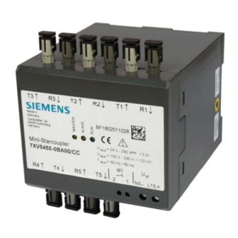
C53000-B1140-C595-1 FO-Connections R1 to R5 and T1 to T5 The receiving optical connectors are marked with R, the transmitting connections with T (see ). The FO-cables must be crossed, that Figure 3: Front view of the Mini-Starcoupler means a FO-connection is done between Transmitter and Receiver and vice versa. Hinweis Push first the nose of the ST connectors carefully in the channel of the device and lock it. -
Page 22: Assignment Switch 1
C53000-B1140-C595-1 Assignment Switch 1 Swicth Position Description open Star cascade connection closed Ring cascade connection open RS232 interface blocked closed RS232 interface can be actived by cable e.g. 7XV5100-4 Not connected open closed open Light ON in idle state Channel 4 closed Light OFF in idle state Channel 4... -
Page 23: Installation And Commissioning
C53000-B1140-C595-1 Installation and Commissioning Warning When operating electrical devices, certain parts are necessarily under dangerous voltage. Therefore, disregard of the operating notes may cause servere bodily injury or property damage. Installation and electrical connection of the device should be performed by adequately qualified personnel only. -
Page 24: Power Supply X2
C53000-B1140-C595-1 4.2.1 Power supply X2 The wires for the auxilliary voltage are screwed on terminal X2 at he bottom side of the device. The assignment of the terminals is printed at the front side or can be read in this manual. Because the device has no ON/OFF switch this switch must be installed external if it´s necessary. -
Page 25: Commissioning
C53000-B1140-C595-1 Commissioning Clip the signal converter on the top–hat rail according EN 50022 with the help of clip-on mounting. Do not make any changes at the device. Check whether the operation data comply with the values on the rating plate. Not change any DIP-switch at the device, before reading this manual. -
Page 26: Application Examples
C53000-B1140-C595-1 Application examples Optical star configuration Several mini-starcouplers can be cascaded in the star configuration, to interface with further addressable protection devices. This star configuration can be extended with the corresponding converter to also include a RS485 bus structure (see manual 7XV5650). Figure 6: Example of a mini starcoupler in a star structure Page 26 of 28 Mini-Star coupler... -
Page 27: Optical Ring Configuration
C53000-B1140-C595-1 Optical ring configuration Several mini starcouplers can be cascaded in the ring configuration. The transmitter channel 1 must be connected with the receiver channel1 in the next mini starcoupler, and then back to the pc/modem. In this manner a ring configuration is created, whereby one additional output per mini starcoupler to a protection device is available Attention! The data from the pc are mirrored back to the pc or modem. - Page 28 C53000-B1140-C595-1 Page 28 of 28 Mini-Star coupler 7XV5450-0BA00...