Siemens NK8223 Manual For Installation, Configuration And Commissioning
Ethernet port
Hide thumbs
Also See for NK8223:
Table of Contents
Advertisement
Quick Links
Advertisement
Table of Contents

Related Manuals for Siemens NK8223


Summary of Contents for Siemens NK8223
- Page 1 NK8000 MP3.20 NK8223 Ethernet Port NK8222 Ethernet Port for a single subsystem NK8225 Ethernet Port with BACnet Gateway Installation Function & Configuration Commissioning Safety Regulations Building Technologies Fire Safety & Security Products...
- Page 2 Data and design subject to change without notice. / Supply subject to availability. © 2006 Copyright by Siemens Switzerland Ltd We reserve all rights in this document and in the subject thereof. By acceptance of the document the recipient acknowledges these rights and undertakes not to publish the document nor the subject thereof in full or in part, nor to make them available to any third party without our prior express written authorization, nor to use it for any purpose other than for which it was delivered to him.
-
Page 3: Table Of Contents
Modifications to the system design and the products .......9 Introduction ...................10 NK8000 system overview ...............10 System limits ..................13 Management-level configurations ............13 NS8210 driver system limits ..............15 NK8223 system limits................16 NK8222 system limits................17 NK8225 system limits................18 3.5.1 NS8011 driver system limits............18 Structure & function ................19 NK822x structure ..................19... - Page 4 CS6 Guarto generated a fault ............53 No fault generated by network failure – MP3.15 and higher..53 9.3.5 System component list.................54 Technical data ..................57 11.1 NK8223 / NK8222 Ethernet Ports ............57 11.2 NK8225 Ethernet Port with BACnet Gateway.........59 11.3 Disposal....................61 11.4 DF8090 Power Supply Supervision Module ...........61...
-
Page 5: About This Document
NK8000 safety and security network. It includes an overview of the system, hard- ware requirements and limitations, and detailed installation and configuration in- structions. Hardware components detailed in this manual include the NK8223 / NK8222 Ethernet Ports, and the NK8225 Ethernet Port with BACnet Gateway. - Page 6 About this document MM8000 06.2006 MM8000 Installation Configuration & Commissioning 006799 MM8000 Configuration Quick Reference 008598 06.2006 06.2006 MM8000 Operation Manual 006798 MM8000 Operation Quick Reference 008082 06.2006 MM8000 Localisation – Engineering Guide 007769 06.2006 MM8000 Release Notes MP3.20 009421 06.2006 MM8000 Release Notes MP3.15 008901...
- Page 7 Liability disclaimer for damage or injuries Before products are delivered, they are tested to ensure they function correctly when used properly. Siemens disclaims all liability for damage or injuries caused by the incorrect application of the instructions, or the disregard of danger adviso- ries.
-
Page 8: Safety Regulations
Safety regulations Safety regulations This section describes the potential sources of danger, and the relevant safety regulations applicable for the use of the Siemens Building Technologies NK8000 products Please read the following work instructions as well as the previous section "About this document"... -
Page 9: Disposal And Recycling
Modifications to the system design and the products Modifications to a system or to individual products may cause faults or malfunc- tioning. Please request written approval from Siemens Building Technologies and from any relevant authorities concerning intended system modifications and system exten- sions. -
Page 10: Introduction
For details, see the DMS8000 Network, Fire & Intrusion Connectivity Guide (edms no. 007083). For serial connectivity to MM8000 / MK8000 / MT8001, the NK8223 / NK8225 uses the proprietary CMSDL protocol. NK8225 products connect to DMS and DESIGO building automation and control systems via BACnet/IP and Ethernet. - Page 11 Introduction What is the NK8223 Ethernet port? The NK8223 is used to connect local and distributed safety and security devices to the NK8000 network. It provides a first level of centralisation and acts as a secure communication partner for the NS8210 NK8000 driver of MM8000 or MK8000, and provides serial connectivity for MM8000, MK8000, and MT8001.
- Page 12 Introduction Fig. 3 Local interactions on NK8222 Fig. 4 Local interactions on NK8225 Building Technologies 007798_g_en NK8000 ICC.doc Fire Safety & Security Products 06.2006...
-
Page 13: System Limits
System limits System limits The following describes the system limits for the NS8210 driver, the NK8223 and NK8222 Ethernet Ports, the NK8225 Ethernet Port with BACnet Gateway, and the NS8011 driver. Management-level configurations The management-level configuration relates to the configuration possibilities of Danger Management Systems, without considering any subsystem connectivity. - Page 14 System limits Fig. 7 MM8000 multiple host station configuration in combination with MK8000 Fig. 8 DESIGO INSIGHT multiple host station configuration Note: CS11 connectivity direct or via Cerloop. NK8000 networks support multiple host configurations with up to 4 hosts (MM8000 / MK8000 / DESIGO INSIGHT). Note: An additional connection over a serial line (CMSDL) is also supported, however this option will limit the CMSDL/IP links to 3 instead of 4.
-
Page 15: Ns8210 Driver System Limits
System limits NS8210 driver system limits NS8210 Ethernet Port connections Currently, there is a limit of 100 NK822x Ethernet Ports per NS8210. NS8210 Transport protocols NS8210 supports the transport protocols CMSDL/IP or CEI 79-5 for communication with the Ethernet Ports. The cryptography option is only supported with the CEI 79- 5 protocol. -
Page 16: Nk8223 System Limits
The first serial port can be configured as an RS232-interface using connector COM1 or as an RS485-interface using connector CN4. Interaction capabilities NK8223 / NK8222 provides programmable interaction programs, including single or multiple triggers (incoming events) and single or multiple effects (outgoing control actions). Interactions are possible between locally connected subsystems. -
Page 17: Nk8222 System Limits
The first serial port can be configured as an RS232-interface using connector COM1 or as an RS485-interface using connector CN4. Extensions with further subsystems require a substitution of NK8222 with NK8223. Interaction capabilities See previous section 3.3. Building Technologies 007798_g_en NK8000 ICC.doc... -
Page 18: Nk8225 System Limits
System limits NK8225 system limits Network capabilities Ethernet IEEE 802.3, 10Base-T, half-duplex, no auto-sensing or auto- negotiation; Single host: – Transport protocol: BACnet/IP Multiple hosts (up to four): – Transport protocol: BACnet/IP DHCP (Dynamic Host Configuration Protocol) is not supported. Static IP- addresses are required for the Ethernet Ports Serial capabilities (RS232) The maximum number of serial lines is 4, allowing connection to up to 4 local units... -
Page 19: Structure & Function
DIMM-PC / 520-I module with 32MB RAM, 32MB Flash disk Real Time Operating System (RTOS) with integrated IP protocol stack Optional 2 RS232 ports add-on board (NK8223 / NK8225 only) Optional PC/104 LON add-on board Optional external I/O module(s) (16 in /8 out) ... -
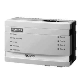
Page 20: Guide To Front Panel
Structure & function 4.1.2 Guide to front panel The front panel of the NK822x houses 9 LED's. The five LED's on the left side are, from top to bottom: Front panel LED Functions Power (hardware – controlled) Power (LED green) Vital functions (LED green) Software vitality (blinking) Tamper (LED bicolour) -
Page 21: Internal Dip Switches
Structure & function 4.1.3 Internal DIP switches The internal DIP switches enable a download session via FTP using a default IP address. Note: There are two internal DIP switches, but only DIP switch 2 is presently used. Internal switch Functions DIP switch 1 Not presently used. -
Page 22: Serial Interfaces
Structure & function 4.1.5 Serial interfaces NK8223 / NK8225 Although the maximum number of serial lines is 4, they are not always used. There are two serial lines available on the base module and two on an expansion module. See the System component list on page 54 for more details about the expan- sion modules. - Page 23 Structure & function Functions CD00251 Rev.A boards CD00251 Rev.B boards panel element Service mode request DL1 yellow Diagnostics LED Blinking if is faulty Blinking if is faulty DL2 red Node in use LED, normally on LED, normally on DL3 yellow Service mode LED normally on LED normally off...
-
Page 24: I 2 C Interface
Structure & function LON address assignment for CS6 Guarto MP3 The LON communication between NK822x and Guarto MP3 is based on logical BACnet addresses for both devices. The physical LON address of the NK822x LON interface is configurable, whereas the logical BACnet address of NK822x is fixed. The default physical LON address of NK822x is: ... - Page 25 Structure & function DF8090 Power supply supervision DF8090 is a module designed for monitoring the DC power supply. It can detect the conditions listed below, shown on the DF8090 local panel (see Fig. 15) and re- port them to NK822x, and in turn to management station (see the following): ...
-
Page 26: Hw Installation
HW Installation HW Installation This section lists the NK8000 hardware installation requirements, and details how to install them. There are two possible installation scenarios: 1. Installation of NK822x in an existing cabinet a. NK822x DIN-rail mounting (typical) b. Mounting of the NK822x euro-size main board in the control unit housing of CS11/CS440, CS6 or SI410 using mounting kits (alternative mounting option if DIN-rail mounting is not possible) ... -
Page 27: Nk822X Hardware Installation
NK822x electrical interfaces (top view) Bottom view: NK822x connectors COM 3 COM 4 COM 1 COM 2 (in place of CN4) Note: NK8222 and some NK8223/NK8225 configurations contain no COM3 or COM4. Back Fig. 17 Serial RS232-interfaces (bottom view) Building Technologies 007798_g_en NK8000 ICC.doc Fire Safety &... - Page 28 HW Installation CN1: Ethernet connector A standard RJ45 connector connects Ethernet. Cat.5 UTP cabling is best suited. Assignment n.c. n.c. n.c. n.c. RS485 used 27Ah 12V Vin = Voltage In Vout = Voltage Out Batt = Battery Fig. 18 NK822x power connections Caution! There is a risk of explosion if the battery is replaced with an incorrect battery type.
- Page 29 HW Installation Characteristic Bus topology Free topology Max. cable length (UTP Cat.4) [m] 1’400 2 100, 1/8W 1 50, 1/8W Termination at each end of segment at center of segment Max. number of nodes per segment Max. number of repeaters Polarity insensitive NK822x has a built-in termination resistor (100Ù) for a doubly terminated bus to- pology that can be enabled by closing the internal jumper JP6.
- Page 30 HW Installation Installation in subsystem housing without DIN-rail NK822x can be installed without the plastic box using the specific mounting kits for CS11/CS440, CS6 or SI410. Fig. 20 NK822x mounting option for CS11 (CC114x) Note: For details on: – CS1142, see EDMS document 004595; –...
-
Page 31: Installation Of Ne8000 Cabinets
HW Installation Installation of NE8000 cabinets 5.2.1 NE8000 hardware requirements Environmental requirements The cabinets for NK822x should always be installed in a clean and safe environ- ment, away from dust, high temperature and humidity, vibrations and impacts. Conditions should match the specific requirements given in the Technical data sec- tion on p. - Page 32 HW Installation 2. Connect power supply. The Vac line wires (1.5 mm ) should be connected as illustrated in Fig. 24. Careful attention should be paid to the correct connections of Vac power lines. Input VAC 1.5 mm wires Fig. 24 VAC power connection Wires pass through 20mm (cut-out) holes* at the top of the cabinet (see Fig.
- Page 33 HW Installation Wiring (1) – front view of cabinet (arrow indicates cut-out holes) Fig. 26 Fig. 27 Wiring (2) – entrance hole indicated by arrow Building Technologies 007798_g_en NK8000 ICC.doc Fire Safety & Security Products 06.2006...
-
Page 34: Sw Installation
SW installation SW installation NK8000 software installation includes the following: – Composer and related tolls for system configuration – NK822x: DMS8000 MP3.20 product setup – Additional tools: NW8202 / NW8204 This section lists the hardware and software requirements for the NW8202 and NW8204 tools, and details how to install them. -
Page 35: Nw8204 Maintenance And Diagnostic Tool
SW installation NW8204 Maintenance and diagnostic tool The NW8204 is a powerful maintenance and diagnostic tool, which provides func- tionalities for (but not limited to) the following: Downloading firmware; Setting IP addresses; Loading default configurations; Using available diagnostic files. Note 1: Part of the NW8204 tool is available in Composer (limited functionality). -
Page 36: Configuring Nk8000
Configuring NK8000 Configuring NK8000 After you have installed the Danger Management System (DMS) and Composer, you need to configure the DMS Once that is done, you perform the NK8000 configuration procedures to get the NK822xs communicating with the Danger Management System. ... -
Page 37: Configuring Nk822X Ip - Via Nw8202
Configuring NK8000 Configuring NK822x IP – via NW8202 This configuration must be performed before the NK822x(s) can be configured at the client’s site. This procedure details how to send the IP configuration informa- tion; that is, the IP address, Subnet mask, and Default address to the NK822x via the NW8202 Tool. - Page 38 Configuring NK8000 Fig. 29 NW8202 IP configuration download instruction window Back Ethernet cable goes here CN1: Ethernet Fig. 30 Connect Ethernet cable Use a crossed Cat. 5 twisted pair patch cable for direct connection between PC and NK822x. While the download is being performed, the FTP Diagnostic window is displayed with the current status of the download.
- Page 39 Configuring NK8000 Once the operation has been performed, a final status notification and instruction window will be displayed. Fig. 32 NW8202 final instruction window 9. Follow the instructions displayed in the final instruction window. 10. Disconnect the NK822x from the PC, and replace the cover. 11.
-
Page 40: Testing The Configuration
Testing the configuration Testing the configuration We recommend that you test connections during the configuration process so you can more easily narrow down the cause of any problems. This is because you may have problems in run-time where no error message is generated. Checking the DMS –... -
Page 41: Maintenance And Diagnostics
Maintenance and diagnostics Maintenance and diagnostics There are two maintenance and diagnostic applications available for NK8000 net- works. One application (or tool), the NW8204 tool, is contained in the product in- stallation CD. The other, the NK8000 Web Server tool, is available via Internet Ex- plorer. -
Page 42: The Nw8204 Maintenance And Diagnostic Tool
Maintenance and diagnostics The NW8204 maintenance and diagnostic tool The NW8204 is a powerful maintenance and diagnostic tool. In the event that a problem occurs during or after NK822x configuration, you use the NW8204 main- tenance tool’s FTP (File Transfer Protocol) and diagnostic interface to locate where the problem occurred so you can resolve it. - Page 43 Maintenance and diagnostics The NK8204 main window appears. Fig. 35 NK8204 main window (installed GUI) 3. Insert the NK IP Address (NK822x). Note: Inserting an incorrect IP address causes the following window to appear. If you receive this message, select ‘OK’ and re-type the IP Address. If you want to enter the NK822x default IP address 192.168.9.41, you can use the menu “Set Default IP Address”...
-
Page 44: Upload Diagnostic Files
Maintenance and diagnostics Fig. 37 NW8204 main window with open connection (installed GUI) Menu item not displayed in NK8000 Web Server NW8204 tool Menu item not displayed in NK8000 Web Server NW8204 tool History frame Error frame This section not displayed in NK8000 Web Server NW8204 tool ... -
Page 45: Nw8204 Diagnostic Functions
Maintenance and diagnostics Note: Every time you select the ‘Save EEProm on File’ button, you overwrite any existing EEProm.LOG file. EVENT.LOG – This file is present only after the EEProm is full for the first time. It contains (up to) the four most recent backups of the EEProm.LOG file. EEProm.LOG and EVENT.LOG are only available on NK822x mainboards with index CD99050/E or higher. - Page 46 Read Product ID Reads the Product ID from the NK822x. The Product ID is used to distinguish be- tween NK8222, NK8223, and NK8225. Read HW Conf. ID Reads the HW Configuration ID from the NK822x. The HW Conf. ID is used to check the HW Configuration from a remote location: –...
-
Page 47: Menu "Send Default Configuration File
Maintenance and diagnostics Read DLL Version Reads all subsystems configured. Displays a dialog box with a list of configured subsystems organised by name, number, and creation date. Menu “Send Default Configuration File” 9.1.4 Sends a default configuration file containing only the new IP-configuration to the NK822x. -
Page 48: The Nk8000 Web Server Tool
Maintenance and diagnostics The NK8000 Web Server tool As described in the beginning of section 9, the NK8000 Web Server tool provides an NS8210 diagnostic utility in addition to the NW8204 tool. The NS8210 provides NK822x branch status information, and also a context command menu for each NK822x branch upon selection. - Page 49 Maintenance and diagnostics 3. Select ‘Details’. 4. Check the FTP Server box, then select ‘OK’. 5. Select ‘Next’. Note: You may be able to ‘Browse’ to select where you want to store the utility. 6. Select ‘Finish’. If you install IIS after installing MM8000 / MK8000, you must perform the follow- ing steps to reset the registry keys: Select MM8000 folder ...
- Page 50 Maintenance and diagnostics NK8000 Web Server startup window – changing user type Fig. 42 Using NS8210 diagnostic tool The left frame of the NS8210 utility window displays a list of NK822x branches in the NK8000 network. The right frame displays the status of those branches. (See Fig.
- Page 51 Maintenance and diagnostics Using NW8204 Web Server tool You access the NW8204 Web Server tool in one of two ways: – Select [‘Hosts’ icon] Start Diagnostic Utility – Select [NK822x branch] Start Diagnostic Utility There are slight differences in the graphic user interface between the installed NW8204 tool and that on the Web, however all functionalities are available in both tools.
-
Page 52: Correcting Communication Failures
Maintenance and diagnostics Correcting communication failures 9.3.1 NK822x generated a fault If an NK822x generates a fault, there may be one or more causes. The problem may be in the NK822x unit, or in the NK822x connection to the DMS. Check the NK822x Check power, vital function, and diagnostic state on the respective LED, which is located on the front panel of NK822x. -
Page 53: Control Unit Won't Respond
Maintenance and diagnostics Note: Cable quality / length problems can be solved by using LON repeat- ers (for example, NK8020, 542843). For details see NK8020 product datasheet e4215. – Physical LON addresses have to be unique in a LON-segment. ... -
Page 54: System Component List
System component list System component list The following NK8000 components are available: NK8223 Ethernet Port Siemens P/N Code NK8223 CDI-Ethernet Port NK8000 Ethernet port – Base module A6E600005 NK8223.2 – 1 Ethernet line for remote station – 2 serial lines for subsystems/local station NK8000 Ethernet port –... - Page 55 C power supervision module for NK822x; Optional module for supervising the NK8223 power supply and detecting power failures and battery low conditions. It is not needed when NK8223 is installed in a fire or intru- sion control unit, whose power supply is already super- vised.
- Page 56 1. Cannot be used with NK8000 MP1.1 products. NS8210 NK8000 Driver The Ethernet ports NK8223 and NK8222 communicate via the NS8210 NK8000 Driver with the management stations. Every order of a management station (MM8000 or MK8000), where NK8000 connectivity is required must include the NS8210 NK8000 Driver.
-
Page 57: Technical Data
Technical data Technical data 11.1 NK8223 / NK8222 Ethernet Ports Lines to local host 1 RS232 line Up to 9600 baud – Transport protocol: CMSDL – Host (single host only): – MM8000 or MK8000 equipped with NS8012 CDI-Net Driver –... - Page 58 DF8090 Power Supply Supervision Module Supervision of power supply and battery backup Module Regulatory Approvals EN 55022 EMC emission (CE conformity) EN 50130-4 EMC immunity EN 60950-1 LVD (NK8223 installed in NE8001) Building Technologies 007798_g_en NK8000 ICC.doc Fire Safety & Security Products 06.2006...
-
Page 59: Nk8225 Ethernet Port With Bacnet Gateway
– CMXDL protocol (CF9003) RS485: 9600 baud – Burle protocol (Philips-Burle) RS232: up to 9600 baud – CDDL/CDSF (Siemens Simatrix) RS232: 2400 baud – CDDL/CDSF (other control units) RS232: up to 9600 baud – SDN-T/VBF (D100, SIGMASYS) RS232 4800, 9600 baud... - Page 60 Technical data Detailed specifications for LON network: http://www.echelon.com/Support/documentation/ Section: Engineering Bulletins → Media & Wiring – Power supply requirements Input voltage (DC power supply to NK8225 board) 10-33 Vdc – Power (NK8225 processor board) 6,34 W – Power (fully equipped NK8225) 8,34 W –...
-
Page 61: Disposal
+10 ... +50 °C Operation: 10 … 95%, non condensing Humidity: Weight NE8002 cabinet only 6.2 Kg NE8001 cabinet with power supply 7.3 Kg NE8001 + with NK8223 (fully equipped) 8.5 Kg Building Technologies 007798_g_en NK8000 ICC.doc Fire Safety & Security Products 06.2006... - Page 62 Siemens Switzerland Ltd Building Technologies Group International Headquarters Fire Safety & Security Products Gubelstrasse 22 © 2006 Copyright by CH-6301 Zug Siemens Switzerland Ltd Tel +41 41 724 24 24 Data and design subject to change without notice. Fax +41 41 724 35 22 Supply subject to availability.