Siemens NK8222 Installation, Function & Configuration
Ethernet port for a single subsystem, ethernet port, cei interface for a single subsystem, ethernet port for a single subsystem, modbus gateway
Hide thumbs
Also See for NK8222:
Table of Contents
Advertisement
NK8000 MP4.40
NK8222 Ethernet Port for a single subsystem
NK8223 Ethernet Port
NK8225 Ethernet Port
NK8231 CEI interface for a single subsystem
NK8232 Ethernet Port for a single subsystem
NK8235 Ethernet Port
NK8237 Modbus Gateway
Installation
Function & Configuration
Commissioning
Safety Regulations
Building Technologies
Fire Safety & Security Products
Advertisement
Table of Contents

Related Manuals for Siemens NK8222


Summary of Contents for Siemens NK8222
- Page 1 NK8000 MP4.40 NK8222 Ethernet Port for a single subsystem NK8223 Ethernet Port NK8225 Ethernet Port NK8231 CEI interface for a single subsystem NK8232 Ethernet Port for a single subsystem NK8235 Ethernet Port NK8237 Modbus Gateway Installation Function & Configuration Commissioning...
- Page 2 Data and design subject to change without notice. / Supply subject to availability. © 2011 Copyright by Siemens Switzerland Ltd We reserve all rights in this document and in the subject thereof. By acceptance of the document the recipient acknowledges these rights and undertakes not to publish the document nor the subject thereof in full or in part, nor to make them available to any third party without our prior express written authorization, nor to use it for any purpose other than for which it was delivered to him.
-
Page 3: Table Of Contents
Documentation changes and corrections in this edition ...12 System limits ..................13 NS8210 driver system limits ..............13 NS8011 driver system limits ..............13 NK8222/NK8223/NK8225 system limits ..........14 NK8231/NK8232/NK8235/NK8237 system limits ........15 NK822x Structure and Functions ............17 Front panel ....................17 Internal DIP switches ................18 Internal jumpers ..................18... - Page 4 Software installation ................42 NW8202 IP configuration download tool..........42 7.1.1 NW8202 hardware requirements..........42 7.1.2 NW8202 software requirements ..........42 7.1.3 NW8202 installation..............42 NW8204 Maintenance and diagnostic tool ..........43 7.2.1 NW8204 Hardware requirements ..........43 7.2.2 NW8204 Software requirements..........43 7.2.3 NW8204 Installation..............43 Configuring NK8000................44 Configuration checklist ................44 Configuring NK82xx IP –...
-
Page 5: About This Document
Training program information including the Siemens intranet link A complete list of all available DMS8000 documents Instructions for how to obtain a document via the Siemens intranet using the Siemens Asset Portal A map of relevant documents for each target audience group ... - Page 6 Safety regulations 3. In the resulting area on the right, select the document type (e.g. Contacts, Data Sheet, etc). For more information such as Siemens news and announcements, visit the STEP Web portal at: https://workspace.sbt.siemens.com/content/00001123/default.aspx Operational and safety regulations Before beginning work on the system you must have read and understood the related documents, in particular the "Safety regulations"...
- Page 7 Update for hardware modifications required by CE conformity regulations 007798_b_en 02.2004 Update for NK8000 (CDI-WAN) MP2.11 NK8223 R2.11, NK8222 R2.11 007798_a_en 10.2003 First release for CDI-WAN MP2.1 NK8223 R2.1, NK8222 R1.0 e4414c 07.2003 Update for NK8210 R1.31-01, NK8223 R1.31-01 e4414b 02.2003 Release of CDI-WAN MP1.1 e4414a 11.2001...
-
Page 8: Safety Regulations
Country-specific standards Siemens Building Technologies products are developed and produced in compli- ance with the relevant international and European safety standards. This document provides warnings and recommendations specific to NK8000 products. Any addi-... -
Page 9: Disposal And Recycling
Modifications to the system design and the products Modifications to a system or to individual products may cause faults or malfunc- tioning. Please request written approval from Siemens Building Technologies and from any relevant authorities concerning intended system modifications and system exten- sions. -
Page 10: Introduction
The NK8000 family includes: NK8222 Ethernet port: LAN/WAN (CMSDL/IP, CEI-79) and Dial-up (CEI-79) communication unit supporting one subsystem connection over RS232 line or CerCom/LON bus, and locally connected DF8000 I/O units. It can provide local interactions between points in the connected subsystem and I/O. -
Page 11: Interactions
Introduction Interactions Local interactions Interactions are possible between the subsystems connected to each NK82xx unit and the locally connected I/O modules. Incoming messages can trigger one or more command messages to other subsystems. Thanks to the high reliability of the NK82xx units, these interactions are more secure than reactions and sequences programmed on the management station level. -
Page 12: Documentation Changes And Corrections In This Edition
Introduction Modbus GW functionality for FS20/FS720 – 3.2, p.13 NS8011 driver: limit of 64 BACnet/IP connections per DMS8000 Server/FEP Station 5, p.23 New NK823x mainboard revisions 5.1, p.23 New LED blinking signal for Modbus GW diagnostic 10, p.49 SNMP functions 10.4, p.61 Enhanced web server functions for remote diagnostics 2.3.1... -
Page 13: System Limits
System limits System limits The following describes the system limits for the NK82xx units and the correspond- ing NS82xx drivers for DMS8000 (MM8000 and MK8000) systems. NS8210 driver system limits NS8210 Ethernet Port connections (CMSDL/IP and CEI 79-5) Currently, there is a limit of 500 NK82xx units per NS8210. Please contact customer support for configurations above 100 NK82xx NS8210 Transport protocols NS8210 supports the transport protocols CMSDL/IP or CEI 79-5 for communication... -
Page 14: Nk8222/Nk8223/Nk8225 System Limits
The serial lines can also be used for a local host or a dial-up host connec- tion. NK8222: The maximum number of serial lines is 2 (on the CPU module). Only one connection to a local unit (intrusion, access control, fire, gas detection, CCTV con- trol units) is allowed. -
Page 15: Nk8231/Nk8232/Nk8235/Nk8237 System Limits
System limits NK8231/NK8232/NK8235/NK8237 system limits Network capabilities (upstream towards management system host) 2 Ethernet interfaces IEEE 802.3, 10/100 Base-T with auto-negotiation, half/full- duplex with auto-sensing, auto-crossover (thus eliminating the need for cross- over cables) Single host transport protocols: ... - Page 16 System limits Interaction capabilities NK8232 and NK8235 provides programmable interaction programs, including sin- gle or multiple triggers (incoming events) and single or multiple effects (outgoing control actions). Interactions are only possible between locally connected subsys- tems. Subsystems supported: see list on page 11 ...
-
Page 17: Nk822X Structure And Functions
NK822x Structure and Functions NK822x Structure and Functions The NK822x is composed of an electronic board (with optional plug-ins) installed in a compact and robust plastic box. Fig. 1 NK822x Ethernet port (NK8223 in this example) Front panel The front panel of the NK822x houses 9 LED's. The five LED's on the left side are, from top to bottom: Front panel LED Functions... -
Page 18: Internal Dip Switches
NK822x Structure and Functions Internal DIP switches The internal DIP switches enable a download session via FTP using a default IP address. Note: There are two internal DIP switches, but only DIP switch 2 is presently used. Internal switch Functions DIP switch 1 Not presently used. -
Page 19: Serial Interfaces
Although the maximum number of serial lines is 4, they are not always used. There are two serial lines available on the base module and two on an expansion module. NK8222 This model is equipped with two serial lines only available on the base module. - Page 20 NK822x Structure and Functions LON panel Functions CD00251 Rev.A boards CD00251 Rev.B boards element Service mode request DL1 yellow Diagnostics LED Blinking if LON is faulty Blinking if LON is faulty DL2 red Node in use LED, normally on LED, normally on DL3 yellow Service mode LED normally on...
-
Page 21: Ethernet Interface
NK822x Structure and Functions Ethernet interface The NK822x main board is equipped with one Ethernet interface and an RJ-45 connector. A green LED (internal) flashes when data is received or transmitted. Back Ethernet connector on NK822x Fig. 5 Ethernet connector on NK822x Building Technologies 048_DMS_NK8000_ICC_MP4.40_A6V10062437_a_en.doc Fire Safety &... -
Page 22: I 2 C Interface: I/O And Power Supervision
NK822x Structure and Functions C interface: I/O and power supervision This interface allows for a direct support of: Direct digital input/output: One or two DF8040 (CF9040) input modules One DF8020 (CF9020) output module Power supply supervision: ... -
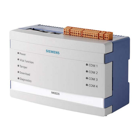
Page 23: Nk823X Structure And Functions
NK823x Structure and Functions NK823x Structure and Functions The NK823x is composed of an electronic board (with optional plug-ins) installed in a compact and robust plastic box. Note that NK823x units with build state up to 04 are equipped with the NKM8001- A1 mainboard that do not support locally connected DF8000 I/O modules. -
Page 24: Internal Dip Switches
NK823x Structure and Functions The four LED's on the right side are, from top to bottom: Front panel LED (right Functions Com1 Status Com1 Red: Com2 Status Com2 Green: Com3 Status Com3 Com4 Status Com4 Tab.6. LED functions on the front panel, right side Internal DIP switches The internal DIP switches (S101) enable a download session via FTP using a de- fault IP address. -
Page 25: Serial Interfaces
NK823x Structure and Functions S1: Reset button S2: Tamper switch S101: DIP-Switches X102 X103 X101 X104 X105 X111 Fig. 9 NK823x internal DIP switch and jumpers (NKM8001-A2 mainboard) Serial interfaces NK8231.2, NK8232.2, NK8235.2 and NK8237.2: These models are equipped with two serial lines available on the NK823x main board. -
Page 26: I 2 C Interface: I/O And Power Supply Supervision
NK823x Structure and Functions X102 onboard inputs Signal Circuit 1 Circuit 2 (internal power supply) (external power supply) Input 1 (Mains failure) Input 2 (Battery fault) Input 3 (Power supply fault) Common + Val - Val X101 onboard relay output Signal Circuit Common... - Page 27 NK823x Structure and Functions DF8090 Power supply supervision DF8090 is a module designed for monitoring a 12V DC power supply. It can detect the conditions listed below, shown on the DF8090 local panel (see Fig. 10) and re- port them to NK823x, and in turn to management station (see the following): ...
-
Page 28: Ethernet Interfaces
NK823x Structure and Functions Ethernet interfaces The NK823x main board is equipped with two Ethernet interfaces The two RJ-45 connectors also include 2 LEDs (yellow and green) reporting the LAN status as fol- lows: Yellow LED: if on, a 100 Mbps link is active. ... -
Page 29: Hardware Installation
2. Connect subsystems: Subsystem lines using the standard RS232 interfaces on COM1 - COM4. Note: Only COM1 and COM2 are available on NK8222. If used in place of COM1, the RS485 interface is on CN4 (NK822x). The LON bus is on CN3. - Page 30 See Fig. 21 p. 36 if using a DF8090 power supply supervision module. Do not connect or disconnect any device when the device is powered on! Top view: NK822x connectors (valid for NK8222, NK8223, and NK8225) Back LON Status LEDs...
- Page 31 27Ah 12V Vin = Voltage In Vout = Voltage Out Batt = Battery NK822x (NK8222, NK8223, NK8225) power supply connection Fig. 14 NK822x power connections Caution! There is a risk of explosion if the battery is replaced with an incorrect battery type.
- Page 32 Hardware Installation COM 1 … COM 4: RS232 connectors RS232 lines are connected to 9pin D-Sub connectors, female type Assignment NK822x COM 1-4 NK823x COM 1-2 NK8235.4: COM 3-4 LON connection (CS6 Guarto) NK822x - CN3: LON LON connections Assignment LON-A LON-B A LON TP/FT-10 network segment can be set up for bus- or free topology.
- Page 33 Hardware Installation C interface C address settings: Addr. 8 Addr. 1 Addr. 2 Addr. 1 (Factory setting) Fig. 15 NK822x I C bus addresses Installation in subsystem housing without DIN-rail NK82xx can be installed without the plastic box using the specific mounting kits for CS11/CS440 and SI410 (NK822x can also be installed in CS6).
- Page 34 Hardware Installation Fig. 17 NK822x mounting option for CS6 Guarto Fig. 18 NK822x mounting option for SI410/420 Intrunet Building Technologies 048_DMS_NK8000_ICC_MP4.40_A6V10062437_a_en.doc Fire Safety & Security Products 06.2011...
-
Page 35: Nk823X Hardware Installation
Hardware Installation 6.1.3 NK823x hardware installation Installation 1. Install the NK82xx unit on the DIN rail. 2. Connect subsystems: Subsystem lines using the standard RS232 interfaces on COM1 - COM4. Note: Only COM1 and COM2 are available on NK8231 and NK8232. ... - Page 36 Hardware Installation X2/X3: Ethernet connector NK823x A standard RJ45 connector connects Ethernet. Cat.5 UTP cabling is best suited. Assignment n.c. n.c. n.c. n.c. X101: Onboard I/O (output relay) Assignment Common NO output NC output X102: Onboard I/O (inputs) Assignment Input 1 (or Mains failure) Input 2 (or Battery fault) Input 3 (or Power supply fault) Common...
- Page 37 Hardware Installation Caution! There is a risk of explosion if the battery is replaced with an incorrect battery type. Use 27Ah 12V batteries. Dispose of the used battery at a recycling point in accordance with local environmental standards and regulations. NK823x –...
-
Page 38: Installation Of Ne8000 Cabinets
Hardware Installation Installation in subsystem housing without DIN-rail NK823x can be installed without the plastic box using the specific mounting kits available for CS11/CS440 and SI410. Note that the NKA8011-A1 mounting plate is also needed together with the specific mounting kits. Fig. - Page 39 Hardware Installation 360 mm 415 mm Fig. 24 Cabinet installation The VAC power supply wires (1.5 mm ) should be connected as illustrated in 0. Careful attention should be paid to the correct connections of Vac power lines. Input VAC 1.5 mm wires Fig.
- Page 40 Hardware Installation 20mm hole cut-outs Fig. 26 Top view of NE8000 cabinet When entering the metallic frame of the cabinet, wires should be protected by a self-extinguishing plastic cord guard (UL94-V2 flammability rating). (Not provided in the supply). Fig. 27 Wiring (1) –...
-
Page 41: Nk8021 Modem Mounting In An Ne8000 Cabinet
Hardware Installation Fig. 28 Wiring (2) – entrance hole indicated by arrow 6.2.2.1 NK8021 modem mounting in an NE8000 cabinet 1. Screw in the modem holder brackets using the holes provided in the back of the cabinet. 2. Slide the modem plate into the brackets. 3. -
Page 42: Software Installation
Software installation Software installation NK8000 software installation includes the following: Composer and related tools for system configuration DMS8000 product setup Additional tools: NW8202 / NW8204 This section lists the hardware and software requirements for the NW8202 and NW8204 tools, and details how to install them. -
Page 43: Nw8204 Maintenance And Diagnostic Tool
Software installation NW8204 Maintenance and diagnostic tool The NW8204 is a powerful maintenance and diagnostic tool, which provides func- tionalities for (but not limited to) the following: Downloading firmware; Setting IP addresses; Loading default configurations; Using available diagnostic files. Note 1: Part of the NW8204 tool is available in Composer (limited functionality). -
Page 44: Configuring Nk8000
Configuring NK8000 Configuring NK8000 After you have installed the Danger Management System (DMS) and Composer, you need to configure the DMS Once that is done, you perform the NK8000 configuration procedures to get the NK82xxs communicating with the Danger Management System. ... -
Page 45: Configuring Nk82Xx Ip - Via Nw8202
Configuring NK8000 Configuring NK82xx IP – via NW8202 This configuration must be performed before the NK82xx(s) can be configured at the client’s site. This procedure details how to send the IP configuration informa- tion; that is, the IP address, Subnet mask, and Default address to the NK82xx via the NW8202 Tool. - Page 46 Configuring NK8000 Note the different dip- switch depending on the NK82xx model Fig. 31 NW8202 IP configuration download instruction window Back Ethernet cable goes here (NK822x) Fig. 32 Connect Ethernet cable on NK822x Back X3: Ethernet 1 X2: Ethernet 2 Ethernet cable goes here (NK823x)
- Page 47 Configuring NK8000 Fig. 34 NW8202 download status window (FTP Status OK) Once the operation has been performed, a final status notification and instruction window will be displayed. Fig. 35 NW8202 final instruction window 1. Follow the instructions displayed in the final instruction window. Note: Set Dip switch n.2 for NK822x and Dip switch n.1 for NK823x 2.
-
Page 48: Testing The Configuration
Testing the configuration Testing the configuration We recommend that you test connections during the configuration process so you can more easily narrow down the cause of any problems. This is because you may have problems in run-time where no error message is generated. Checking the DMS –... -
Page 49: Maintenance And Diagnostics
Maintenance and diagnostics Maintenance and diagnostics 10.1 Kernel update The NK8237 Kernel is the main component of the operating system, which acts as a bridge between the application and the hardware level. In certain conditions, it may be necessary to update the NK8237 Kernel, following specific instructions of the technical support. -
Page 50: Snmp Monitoring
Maintenance and diagnostics 10.2 SNMP monitoring The NK823x units can support the SNMP protocol (Simple Network Management Protocol) to enable remote stations to monitor the units for conditions that may re- quire administrative attention. Using the SNMPv1 (RFC 1155-1157) on the UDP port 161, the NK823x provides two sets of internal information variables using the community IDs listed here be- low that enable the access to the MIB (Management Information Base) name- space. -
Page 51: The Nw8204 Maintenance And Diagnostic Tool
Maintenance and diagnostics Fig. 38 NK8000 diagnostic tools This section details how to access and use these specialised tools to maintain and troubleshoot an NK8000 network and its components. Many of the functions detailed in this section are available in Composer. See DMS Network, Fire and Intrusion Connectivity and DMS Video Connec- ... - Page 52 Maintenance and diagnostics You are logged in as ‘guest’ (default user type) when the NW8204 window ap- pears. Note: To change user type (for example from ‘guest’ to ‘admin’), select Change User to display the Login window. (See information table below.) User types: There are two ways you can log in to the NW8204 tool.
-
Page 53: File Commands
Maintenance and diagnostics Fig. 41 NW8204 window with open connection (installed GUI) Select do display user login window. See Information box previous page for a description of user types. Note: Available through ‘Host’ menu in NK8000 Web Server NS8210 tool Displays the version of the NW8204 tool. - Page 54 Maintenance and diagnostics Upload file Transfer the selected file to the NK82xx (see how to upload log files in 10.3.4 be- low). Delete/rename file Delete or Rename the selected file in the NK82xx. Refresh Update the file list. Properties Display the detailed properties if the selected file. Download Reset NK Download a file that forces the NK82xx to perform a software reset.
-
Page 55: Uploading Diagnostic Files
Maintenance and diagnostics 10.3.4 Uploading diagnostic files Diagnostic file purposes: The purpose of these files is to record messages of what has taken place with the NK82xx to make it easier to determine if something is wrong, or if something im- portant has taken place. - Page 56 Maintenance and diagnostics version different from version in EEProm EV_EEPROM_PIC24_FLASH_FAILURE PIC24 microcontroller init failed to write the micro- controller flash memory EV_EEPROM_PIC24_PROGRAMMED PIC24 microcontroller init wrote a new firmware into the microcontroller flash memory EV_EEPROM_PIC24_WRONG_HEX PIC24 microcontroller init detected a wrong firm- ware into the microcontroller EV_EEPROM_HW_FAILURE Unable to retrieve information from the EEProm or...
-
Page 57: Nw8204 Diagnostic Functions
Maintenance and diagnostics 10.3.5 NW8204 Diagnostic functions Reset NK Allows you to reset an NK82xx from a remote location. Note: This function is only available when logged in as user “admin”. Save EEPRom on file Stores the content of the EEProm in the file EEProm.LOG on the NK82xx flash disk. - Page 58 Read Product ID Reads the Product ID from the NK82xx. The Product ID is used to distinguish be- tween NK8222, NK8223, and NK8225. Read HW Conf. ID Reads the HW Configuration ID from the NK82xx. The HW Conf. ID is used to check the HW Configuration from a remote location: ...
- Page 59 Maintenance and diagnostics Note: If the IP address shows ‘0000’, no PC was connected to that port. Read HW version Reads the NK823x hardware version (NKM8001-A1, NKM8001-A2, …). Note that NK823x MP4.40 or later firmware is required. Read PIC24FW Ver Reads the PIC24 microcontroller firmware version.
-
Page 60: Menu "Send Default Configuration File
Maintenance and diagnostics 10.3.6 Menu “Send Default Configuration File” Sends a default configuration file containing only the new IP-configuration to the NK82xx. This function allows the download of a default configuration file with new IP pa- rameter settings to any reachable NK82xx, while NW8202 assumes that the NK82xx is set to default IP address before downloading the new configuration. -
Page 61: The Nk8000 Web Server Tool
Maintenance and diagnostics 10.4 The NK8000 Web Server tool As described in the beginning of section 9, the NK8000 Web Server tool provides an NS8210 diagnostic utility in addition to the NW8204 tool. The NS8210 provides NK82xx branch status information, and also a context command menu for each NK82xx branch upon selection. - Page 62 Maintenance and diagnostics 3. Select Details 4. Check the FTP Server box, then select OK 5. Select Next Note: You may be able to Browse to select where you want to store the utility 6. Select Finish If you install IIS after installing MM8000 / MK8000, you must perform the follow- ing steps to reset the registry keys: Press Start ...
- Page 63 Maintenance and diagnostics User types: There are two ways you can log in to the NK8000 Web tool. Guest user: (Default) User Name = guest / Password = guest – (Read only privileges, Automatic login) Administrative user: Call customer support for username and password. –...
- Page 64 Maintenance and diagnostics Out scan: Set the NK82xx unit out of scan. After that, the In Scan command will be available. Reset: Launch a reset of the NK82xx unit Synchronize date/time: Send a date & time message to the NK82xx unit. ...
- Page 65 Maintenance and diagnostics Branch description: Enter the description name (or the first letter of name). Multiple matches can occur as shown in Fig. 52 Branch network address: Specify the IP address (or the first part of the 4- number IP address).
-
Page 66: Correcting Communication Failures
Maintenance and diagnostics 10.5 Correcting communication failures 10.5.1 NK82xx generated a fault If an NK82xx generates a fault, there may be one or more causes. The problem may be in the NK82xx unit, or in the NK82xx connection to the DMS. Check the NK82xx Check power, vital function, and diagnostic state on the respective LED, which is located on the front panel of NK82xx. -
Page 67: Control Unit Won't Respond
Maintenance and diagnostics Note: Cable quality / length problems can be solved by using LON repeaters RS232 Diagnostic information about the RS232 state can be obtained from the LEDs placed on the front panel of NK82xx. Typical problems of RS232 communication are: ... -
Page 68: Secure Operation Requirements
Compliance with local regulations must be addressed. This can concern paper listings as well as tapes and memory support. For further information on general security issues regarding Siemens products, please refer to the internal documentation and procedures on this subject. - Page 70 Siemens Switzerland Ltd Industry Sector Building Technologies Division International Headquarters Fire Safety & Security Products © 2011 Copyright by Gubelstrasse 22 Siemens Switzerland Ltd CH-6301 Zug Data and design subject to change without notice. Tel. +41 41 724 24 24 Supply subject to availability.