Table of Contents
Advertisement
Quick Links
Operation &
Maintenance Manual
PW118MR-
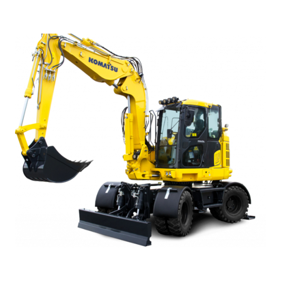
WHEELED EXCAVATOR
SERIAL NUMBERS
PW118MR-11
Unsafe use of this machine may cause serious
injury or death. Operators and maintenance
personnel must read this manual before operating
or maintaining this machine. This manual should
be kept inside the cab for reference and periodically
reviewed by all personnel whowill come into
contact with the machine.
F30003
and up
WARNING
11
ORIGINAL INSTRUCTIONS
Advertisement
Chapters
Table of Contents

Related Manuals for Komatsu PW118MR-11


Summary of Contents for Komatsu PW118MR-11
- Page 1 WENAM00130 Operation & Maintenance Manual PW118MR- WHEELED EXCAVATOR SERIAL NUMBERS PW118MR-11 F30003 and up WARNING ORIGINAL INSTRUCTIONS Unsafe use of this machine may cause serious injury or death. Operators and maintenance personnel must read this manual before operating or maintaining this machine. This manual should...
-
Page 3: Foreword
Komatsu or Ko- matsu approved rebuilt parts or assemblies or others parts of equivalent quality, and that the engine be serviced by an authorized Komatsu distribu- tor. Failure to follow these recommendations could result in ineffective serv- ice, damage to the product or safety risks (including personal injury or death). -
Page 4: Consult This Manual
Continuing improvements in the design of this machine may lead to additional changes that are not reflected in this manual. Consult Komatsu or your Komatsu distributor for the latest available information concerning your machine or with questions regarding information contained in this manual. -
Page 5: Safety Information
FOREWORD SAFETY INFORMATION SAFETY INFORMATION To enable you to use the machine safely, and to prevent personal injury to operators, service personnel or by- standers, the precautions and warnings included in this manual and the safety signs attached to the machine must always be observed. -
Page 6: Safety Labels
Continuing improvements in the design of this machine can lead to changes in detail which may not be reflected in this manual Consult Komatsu or your Komatsu distributor for the latest available information of your machine or for ques- tions regarding information in this manual. -
Page 7: Noise
FOREWORD NOISE NOISE Two labels indicating the machine noise level are affixed on the machine. • Sound pressure level at the operator’s station, measured according to ISO 6396 (Dynamic test method, simulated working cycle). The maximum value of the standard deviation of the meas- ured time-averaged A-weighted emission sound pressure level at the operator’s position is 2.5dB, in accordance with ISO 11201. -
Page 8: Vibration Level
VIBRATION LEVEL FOREWORD VIBRATION LEVEL When used for its intended purpose, levels of vibration for the earth—moving machine transmitted from the op- erator’s seat are lower than or equal to the test vibrations for the relative machinery class in compliance with ISO 7096. - Page 9 FOREWORD VIBRATION LEVEL • Do not repeatedly handle and lift loads. WENAM00130...
-
Page 10: Introduction
INTRODUCTION FOREWORD INTRODUCTION MAIN USE OF MACHINE This Komatsu machine is designed to be used mainly for the following work: • Digging • Ditching work • Loading • levelling For details of work procedure, see MACHINE OPERATIONS AND CONTROLS “RECOMMENDED APPLICA- TIONS (3-207)”. -
Page 11: Directions Of Machine
FOREWORD INTRODUCTION DIRECTIONS OF MACHINE RKA36001 (A) Front (D) Right (B) Rear (E) Operator's seat (C) Left In this manual, the terms front, rear, left, and right refer to the travel direction as seen from the operator's seat when the operator's seat is facing the forward direction. VISIBILITY FROM OPERATOR'S SEAT The visibility of this machine required by visibility standards ISO 5006 are shown in the drawing below. - Page 12 INTRODUCTION FOREWORD The shaded areas (A) and (B) in the figure show areas with obscured views even if the machine is equipped with mirrors and other visibility assistance devices. Be fully aware that there are one or more areas where the operator has no visibility when using the machine.
-
Page 13: Engine Technology To Conform Exhaust Gas Emission
• Komatsu’s Urea SCR system: A device which decomposes the toxic nitrogen oxides (NOx) mixed in the exhaust gas into harmless nitrogen and water. Spraying the reagent (Diesel Exhaust Fluid) into the exhaust gas produces a reaction between the nitrogen oxides and ammonia generated from the urea solution and decomposes the nitrogen oxides into nitrogen and water. -
Page 14: Product Information
PRODUCT INFORMATION FOREWORD PRODUCT INFORMATION When requesting service or ordering replacement parts, inform your Komatsu distributor of the following items. LOCATION OF PRODUCT IDENTIFICATION NUMBER (PIN)/MACHINE SERI- AL NO. This is on the left side of the mounting location of the swing bracket. -
Page 15: Fluorinated Greenhouse Gases
This is displayed on the machine monitor. YOUR MACHINE SERIAL NUMBERS AND DISTRIBUTOR Machine serial No. Engine serial No. Product identification number (PIN) Manufacturer's name: Komatsu Italia Manufacturing S.p.A Address: Via Atheste, 4 35042 Este (PD) Italy Distributor name Address... -
Page 16: Serial Plate
SERIAL PLATE FOREWORD SERIAL PLATE SERIAL NUMBER MODEL WEIGHT YEAR OF CONSTRUCTION PRODUCT IDENTIFICATION NUMBER ENGINE POWER MANUFACTURER 1-14 WENAM00130... -
Page 17: Declaration Of Conformity
FOREWORD DECLARATION OF CONFORMITY DECLARATION OF CONFORMITY The manufacturer: Komatsu Italia Manufacturing S.p.A Via Atheste, 4 35042 Este (PD) Italy Declares that this machine: PW118MR-11 Fulfils all the relevant provisions of following EC Directives: Machine Directive 2006/42/EC Electro Magnetic Compatibility Directive... -
Page 18: Table Of Contents
TABLE OF CONTENTS FOREWORD TABLE OF CONTENTS FOREWORD..............................1-1 CONSULT THIS MANUAL ........................1-2 SAFETY INFORMATION .......................... 1-3 SAFETY LABELS ............................. 1-4 NOISE............................... 1-5 VIBRATION LEVEL........................... 1-6 VIBRATION - OPERATING CONDITION ................... 1-6 GUIDE TO REDUCE VIBRATION LEVELS ON MACHINE ..............1-6 INTRODUCTION ............................ - Page 19 OTHER TROUBLE......................... 3-251 MAINTENANCE............................... 4-1 PRECAUTIONS FOR MAINTENANCE ..................... 4-2 CHECK SERVICE METER READING ....................4-2 KOMATSU GENUINE REPLACEMENT PARTS ................4-2 KOMATSU GENUINE LUBRICANTS ....................4-2 ALWAYS USE CLEAN WASHER FLUID .................... 4-2 FRESH AND CLEAN LUBRICANTS ....................4-2...
- Page 20 TABLE OF CONTENTS FOREWORD CHECK DRAINED OIL AND USED FILTER..................4-2 PRECAUTIONS FOR REFILLING OIL OR FUEL ................4-2 PRECAUTIONS FOR ADDING DEF ....................4-2 WELDING INSTRUCTIONS....................... 4-2 DO NOT DROP THINGS INSIDE MACHINE ..................4-2 DUSTY JOBSITES..........................4-2 AVOID MIXING OIL..........................4-3 LOCKING INSPECTION COVERS ....................
- Page 21 RECOMMENDED FUEL, COOLANT, AND LUBRICANT ................7-5 LUBRICATION CHART ........................7-5 METHOD FOR USING FUEL, COOLANT AND LUBRICANTS ACCORDING TO AMBIENT TEMPERA- TURE ............................. 7-7 RECOMMENDED BRANDS AND QUALITIES OTHER THAN KOMATSU GENUINE OILS ....7-8 INDEX................................8-1 1-19 WENAM00130...
-
Page 22: Wenam00130
WENAM00130... -
Page 23: Safety
SAFETY Please read and make sure that you fully understand the precautions descri- bed in this manual and the safety labels on the machine. When operating or servicing the machine, always follow these precautions strictly. WENAM00130... -
Page 24: Safety Labels
If the safety labels are damaged, lost, or cannot be read properly, replace them with new ones. For details of the part numbers for the safety labels, see this manual or the actual label, and place an order to your Komatsu distributor. •... -
Page 25: Location Of Safety Labels
SAFETY SAFETY LABELS LOCATION OF SAFETY LABELS RKA64590 WENAM00130... - Page 26 SAFETY LABELS SAFETY (1) Combined safety information label (10) Caution when standing in operator's cab (a) Warning for operation, inspection and maintenance (11) Caution for blast jobsite (b) Warning: Lock the controls before leaving the ma- (12) Warning for operation, inspection and mainte- chine nance (c) Emergency steering...
-
Page 27: Contents Of Safety Labels
SAFETY SAFETY LABELS (20) Warning when the boom is lowered (29) Caution for high-temperature coolant and hydraul- ic oil (21) Emergency exit (30) Caution against falling (22) Lock front window (31) Caution against high temperature (23) Lifting and fastening decal for transporting (32) Caution for handling battery (24) Warning always fasten safety belt (33) Caution stop rotation during inspection and main-... - Page 28 SAFETY LABELS SAFETY (b) Warning: Lock the controls before leaving the machine • Before leaving the driving seat, always raise the safety lock lever. (c) Emergency steering Emergency steering must only be used to stop the machine safely in case of engine failure. (d) Warning against high-voltage cable •...
- Page 29 SAFETY SAFETY LABELS (e) No passengers warning • No passengers allowed to ride on the machine while it is moving. (f) Warning: danger of falling objects and bucket interference • Do not work where there is danger of falling objects. •...
- Page 30 SAFETY LABELS SAFETY (4) Danger do not enter within swing range (09133-A1681) • There is a danger of getting caught when upper structure swings. • Stay away from the rotation radius. (5) Caution for overload machine (227-00-31990) • Do not exceed the specified lifting load. (6) Caution for handling accumulator and gas spring (09659-A057B) •...
- Page 31 SAFETY SAFETY LABELS (7) Lifting capacity diagram (227-00-31440) (8) Pay attention to the correct position of the wiper (22B-00-32710) • Consult the manual for the correct closure procedure of the rear window. • Check that the wiper is in the correct position before clos- ing the rear window.
- Page 32 SAFETY LABELS SAFETY (9) Lifting warning (20E-00-K1450) Do not lift beyond the machine's maximum permissible load lim- (10) Caution when standing in operator's cab (09839-A0481) • Take care when standing in the operator cab. • Before standing up from the operator's seat (such as when opening or closing the front window, or when removing or installing the bottom window, or when adjusting the opera- tor's seat), always lower the work equipment completely to...
- Page 33 SAFETY SAFETY LABELS • Keep the machine at a safe distance from an explosive area and from a detonator. (12) Warning for operation, inspection and maintenance (09651-A0841) Read the manual before operating, inspection, maintenance, disassembly, assembly and transportation. (13) Warning for quick coupler system (20J-00-11271) •...
- Page 34 SAFETY LABELS SAFETY • Before standing up from operator's seat. • Lower the work equipment to the ground and move safety lock lever (located near seat) to lock position to avoid hit- ting unlocked operation levers. • Sudden and accidental movements of the machine can cause serious injury or death.
- Page 35 SAFETY SAFETY LABELS (a) Warning against high-voltage cables • An electrocution hazard if the machine is brought too near to electric power lines. • Keep a safe distance from electric power lines. (b) Warning when leaving the operator's seat • Before standing up from operator's seat.
- Page 36 SAFETY LABELS SAFETY (18) Warning for reversing manoeuvres (09802-A0640) To prevent SEVERE INJURY or DEATH, do the following be- fore moving machine or its attachments: • Honk horn to alert people nearby. Be sure no one is on or near machine or in swing area. Rotate cab for full view of travel path if it can be done safe- Use spotter if view is obstructed.
- Page 37 SAFETY SAFETY LABELS (21) Emergency exit (09844-00050) (22) Lock front window (22P-00-11381) (23) Lifting diagram (227-00-31161) (24) Warning always fasten safety belt (09848-A0480) • If the machine tipping, the operator may be thrown out of the operator's seat. • Always fasten the safety belt. Read the manual for more detail.
- Page 38 SAFETY LABELS SAFETY WARNING Before moving, look around and at mirror and monitor to confirm that no one is around the machine. Failure to do so can result in serious injury or death. (26) Warning for handling ROPS (09620-J2001, 09620-A3001) •...
- Page 39 SAFETY SAFETY LABELS (29) Caution for high-temperature coolant and hydraulic oil (09653-A0481) • Never remove the cap when the engine is at operating temperature (high). Steam or high temperature oil blowing up from the radiator or hydraulic tank will cause personal injury and/or burns.
- Page 40 SAFETY LABELS SAFETY (32) Caution for handling battery (09808-A0881) • The sign indicates an electrical hazard when handling the cable. • To ensure the correct and safe use, it is recommended to read the manual. (33) Caution stop rotation during inspection and maintenance (09667-A0481) •...
-
Page 41: General Precautions Common To Operation And Maintenance
GENERAL PRECAUTIONS COMMON TO OPERATION AND MAINTE- SAFETY NANCE GENERAL PRECAUTIONS COMMON TO OPERATION AND MAINTENANCE Mistakes in operation, inspection, or maintenance may result in serious personal injury or death. Before per- forming operation, inspection, or maintenance, always read this manual and the safety labels on the machine carefully and obey the warnings. -
Page 42: Precautions To Prevent Fire
GENERAL PRECAUTIONS COMMON TO OPERATION AND MAINTE- NANCE SAFETY KEEP MACHINE CLEAN • If you get on or off the machine or perform inspection and maintenance on the machine with mud or oil, you may slip and fall, and it is dangerous. Remove any residual mud or oil from the machine. Always keep the machine clean. - Page 43 GENERAL PRECAUTIONS COMMON TO OPERATION AND MAINTE- SAFETY NANCE • Do not jump off the machine. There is the danger of falling and it may cause personal injury. • The fume generated by a fire contains harmful materials which have a bad influence on your body when they are inhaled.
-
Page 44: Precautions When Getting On Or Off Machine
Do not get on or off the machine with tools in your hand. • If any step is damaged or deformed, do not stand on it. Repair or replace the damaged or deformed step immediately. Ask your Komatsu distributor for repair or replacement. 2-22... - Page 45 GENERAL PRECAUTIONS COMMON TO OPERATION AND MAINTE- SAFETY NANCE NO JUMPING ON OR OFF MACHINE Getting on or off the moving machine can cause serious personal injury or death. Always observe the following. • Never jump on or off the machine. Never get on or off a moving machine. •...
-
Page 46: Do Not Get Caught In Work Equipment
GENERAL PRECAUTIONS COMMON TO OPERATION AND MAINTE- NANCE SAFETY Attach the boom swing control safety devices. Set the lock lever securely in LOCK position (L). Turn the ignition key to the OFF position (A). Remove the ignition key, close the doors and windows and leaving the key at a preset location. -
Page 47: Protection Against Falling, Flying Or Intruding Objects
No attempt should be made to repair these parts as this may have an adverse effect on component strength or durability. If such a repair is undertaken without authorisation from Komatsu there is a danger that a problem might occur that will lead to serious personal injury. -
Page 48: Precautions Related To Cab Glass
When installing optional parts or attachments which are not written in this manual, the machine weight must not exceed ROPS certified value. Always contact your Komatsu distributor before installing. • Installing some work equipment combinations may cause interference and damage with the cab or other parts of the machine during operation and could cause serious personal injury or death. -
Page 49: Precautions For Operation
SAFETY PRECAUTIONS FOR OPERATION PRECAUTIONS FOR OPERATION PRECAUTIONS FOR JOBSITE INVESTIGATE AND CONFIRM JOBSITE CONDITIONS On the jobsite, there are various hidden dangers that may lead to serious personal injury or death. Before start- ing operations, always check the following to confirm that there is no danger on the jobsite. •... - Page 50 PRECAUTIONS FOR OPERATION SAFETY Voltage of Cables Safety Distance 187000 V Min. 6 m 275000 V Min. 7 m 500000 V Min. 11 m • To prepare for any possible emergencies, wear rubber shoes and gloves. Lay a rubber sheet on the opera- tor's seat, and be careful not to touch the chassis with any exposed part of your body. •...
-
Page 51: Start Engine
Always observe the regulations for jobsite and environmental standards. This machine does not contain asbestos, but any part which is not the genuine part, it has risk of containing asbestos. Always use Komatsu genuine parts. START ENGINE USE WARNING TAGS If there is a "DANGER! Do NOT operate!"... - Page 52 PRECAUTIONS FOR OPERATION SAFETY • Before starting the engine, check that lock lever (1) is in the LOCK position (L) and the gear selector is in neutral (N). • Adjust the mirrors so that the rear of the machine can be seen easily from the operator's seat.
-
Page 53: Precautions For Operation
SAFETY PRECAUTIONS FOR OPERATION • When connecting the jumper cables, turn the starting switch to OFF position for both the failed machine and the normal machine. If the failed machine has a battery disconnect switch, turn it to OFF position, and turn it ON again after connecting the cables. - Page 54 PRECAUTIONS FOR OPERATION SAFETY • Always operate the machine only when seated on the operator's seat. • Before starting to move, check again that there is no people or obstacle in the surrounding area. • Before moving, sound the horn to warn people in the surrounding area.
- Page 55 SAFETY PRECAUTIONS FOR OPERATION • When operating in tunnels, under bridges, under electric wires, or other places where the height is limited, operate slowly and be extremely careful not to let the machine body or work equipment hit anything. When traveling on public roads, follow the road traffic regulations and the following: •...
- Page 56 PRECAUTIONS FOR OPERATION SAFETY • Do not turn on slopes or drive across slopes. Always go down to a flat place to change the position of the machine, then drive it on to the slope again. • Do not drive the machine on a slope covered with the steel plates. Even with slight slopes there is a hazard that the machine may slip.
- Page 57 SAFETY PRECAUTIONS FOR OPERATION • It is dangerous to work under an overhang. Mudslide or rockfall may occur, or the overhang may collapse. Never perform digging under an overhang. • Do not carry out demolition work under the machine. The ground under the machine may collapse and cause the machine to fall.
- Page 58 PRECAUTIONS FOR OPERATION SAFETY • Do not operate the brake pedal abruptly when moving on snowy slopes. Reduce speed and operate the brake intermittently. If necessary, lower the work equipment to the ground to stop the machine. PRECAUTIONS WHEN PARKING MACHINE Unexpected move of the parked machine can cause serious personal injury or death.
-
Page 59: Precautions For Transportation
• This machine may need to be divided into components for transportation depending on the regulation. When transporting the machine, consult your Komatsu distributor. PRECAUTIONS WHEN LOADING AND UNLOADING If handling is improper when loading or unloading the machine, it is dangerous that the machine may tip over or fall. -
Page 60: Towing And Being Towed
PRECAUTIONS FOR OPERATION SAFETY • Run the engine at low idle and drive the machine slowly at low speed. • No not operate any levers when on the ramps. • Never correct your steering on the ramps. If necessary, drive off the ramps onto the ground, correct the di- rection, then enter the ramps again. -
Page 61: Lifting Operation By Using Lifting Device (Optional Equipment)
SAFETY PRECAUTIONS FOR OPERATION • Do not use the work equipment or swing to pull the load in any direction. There is a risk that the hook could break and the load be released, resulting in sudden movement of the machine and a risk of injury. - Page 62 PRECAUTIONS FOR OPERATION SAFETY • The lifting link RLL (Rated Lifting Load) and part number are stamped on the link as shown below. Always be sure to lift within the relevant lifting limits. • Do not use the work equipment or swing to pull the load in any direction. There is a danger that the lifting eye may be damaged due to abnormal loading making it unsafe to lift.
-
Page 63: Precautions For Maintenance
SAFETY PRECAUTIONS FOR MAINTENANCE PRECAUTIONS FOR MAINTENANCE PRECAUTIONS BEFORE STARTING INSPECTION AND MAINTENANCE DISPLAY WARNING TAG DURING INSPECTION AND MAINTENANCE During inspection and maintenance, always display the "DAN- GER! Do NOT operate!" warning tag. If there is a "DANGER! Do NOT operate!" warning tag dis- played, it means that someone is performing inspection and maintenance of the machine. - Page 64 END OF SERVICE LIFE • For safe dismantling of the machine at the end of service life, please contact your Komatsu distributor. STOP ENGINE BEFORE CARRYING OUT INSPECTION AND MAINTENANCE If you are caught or pinched between the work equipment during operation, or exposed to high-temperature or high-pressure liquids, it is dangerous and may cause serious personal injury or death.
- Page 65 SAFETY PRECAUTIONS FOR MAINTENANCE TWO WORKERS FOR MAINTENANCE WHEN ENGINE IS RUNNING To prevent personal injury, do not perform maintenance with the engine running. When it is necessary to per- form the maintenance with the engine running, always observe the following. •...
-
Page 66: Precautions For Check And Maintenance
PRECAUTIONS FOR MAINTENANCE SAFETY • Never jump down from the machine. When getting on and off the machine, always face the machine and maintain at least three-point contact (both feet and one hand, or both hands and one foot) with the hand- rails and steps to ensure that you support yourself. - Page 67 SAFETY PRECAUTIONS FOR MAINTENANCE PRECAUTIONS FOR WELDING Welding operations must always be performed by a qualified welder and in a place equipped with proper equip- ment. There is a hazard of gas, fire, or electric shock when performing welding, so never allow any unqualified person to perform welding.
- Page 68 PRECAUTIONS FOR MAINTENANCE SAFETY PRECAUTIONS WHEN USING HAMMER When using a hammer, pins may come out or metal particles may be scattered. It is dangerous and may cause serious personal injury or death. Always observe the following. • When hitting pins or bucket teeth, broken pieces may be scattered, and it may cause personal injury to the people in the surrounding area.
- Page 69 If the hose or piping mounts are loose or oil or fuel is found to be leaking from the mount, stop operations and tighten to the specified torque. If any damaged or deformed hoses or piping are found, consult your Komatsu distributor. Replace the hose if any of the following problems are found.
- Page 70 Before inflating the tires, always check the condition of the rims and the external condition of the tire to de- tect the presence of dents, cuts, tears of reinforcement or other defects. • If the inflation pressure reduces abnormally or if problems arise with the tires or rims, contact the Komatsu distributor for the necessary repairs. •...
- Page 71 During maintenance or dismantling operations, where there is the risk of contact with hazardous chemical sub- stances, relevant safety precautions should be taken. If any doubt exists, contact your Komatsu distributor. See also “PRECAUTIONS FOR DISPOSING OF WASTE MATERIALS (2-49)” and “MAINTENANCE OF AIR CONDITIONER (2-49)”...
- Page 72 WENAM00130...
-
Page 73: Operation
OPERATION Please read and make sure that you understand the SAFETY section before reading this section. WENAM00130... -
Page 74: General View
GENERAL VIEW OPERATION GENERAL VIEW MACHINE EQUIPMENT NAME RKA61930 WENAM00130... - Page 75 OPERATION GENERAL VIEW RKA63240 (1) Bucket (19) Outrigger cylinders (2) Bucket cylinder (20) Rear right side cover (3) Arm (21) Rear left side cover (4) Arm cylinder (22) Stop - Turn signals (5) 2-piece boom (2nd boom) (23) Air conditioning filter access cover (6) 2-piece boom cylinder (2nd boom) (24) Battery disconnection compartment access cover (7) 2-piece boom (1st boom)
-
Page 76: Cab Equipment Names
GENERAL VIEW OPERATION (37) Komatsu Closed Crankcase Ventilation (hereafter (39) Battery disconnect switch KCCV) ventilator (38) System operating lamp CAB EQUIPMENT NAMES RKA62060 (1) Front window (6) Fire extinguisher (if equipped) (2) Ceiling window (7) Cup holder (3) Door handle... -
Page 77: Controls And Gauges Names
OPERATION GENERAL VIEW CONTROLS AND GAUGES NAMES RKA62690 WENAM00130... - Page 78 GENERAL VIEW OPERATION (1) Machine monitor (31) Monitor (2) Monitor control switch (32) Steering wheel (3) Air conditioner control switch (33) Steering wheel height adjuster (4) Parking lights - instrument lighting - low beam (34) 2nd-line attachment proportional switch switch (35) Horn push button (5) R.H.
- Page 79 OPERATION GENERAL VIEW MACHINE MONITOR EQUIPMENT NAME AA: Display with KomVision and camera - BB: Display with gauges only (street mode activated) (1) Function switches (16) Coolant temperature alarm caution lamp (2) ECO gauge (17) Air conditioner control panel (9) Fuel consumption gauge (18) Street mode switch (4) KomVision Display (19) Buzzer silence switch...
- Page 80 GENERAL VIEW OPERATION (32) Travel alignment caution lamp (40) Alarms caution lamp (33) Emergency rotation brake release caution lamp (41) Axle locking mode caution lamp (flashing) (42) Travel direction caution lamp (34) Preheating caution lamp (43) Steering mode caution lamp (35) Auto-deceleration caution lamp (44) Wheel alignment caution lamp (36) Work mode warning light...
-
Page 81: Explanation Of Components
OPERATION EXPLANATION OF COMPONENTS EXPLANATION OF COMPONENTS To perform suitable operations correctly and safely, it is important to completely understand methods of operat- ing the equipment, and the meanings of the displays. EXPLANATION OF MACHINE MONITOR EQUIPMENT RKA60980 AA: Display with KomVision and camera - BB: Display with gauges only (street mode activated) (1) Warning display (6) Steering display (2) Pilot display... -
Page 82: Basic Operation Of Machine Monitor
EXPLANATION OF COMPONENTS OPERATION BASIC OPERATION OF MACHINE MONITOR BASIC OPERATION OF MACHINE MONITOR WHEN STARTING ENGINE IN NOR- MAL SITUATION RKA61000 • When rotating the ignition key to the ON position, screens AA, BB, CC, DD are displayed sequentially at two seconds intervals until the standard EE screen is reached. - Page 83 End screen when any message has been received If there is any message from your Komatsu distributor, it is dis- played on the end screen. In this case, turn the starting switch to ON position to re-check the message, and if it is the message requesting response, send back your reply.
- Page 84 On the screen LL, press F1 and the screen switches to the screen CC without entering the ID number. REMARK • Contact your Komatsu distributor for details of the method of setting, changing, or canceling the ID number. • Depending on the set value of the “Operator ID Holding Time with Key OFF”, even when operator ID of has been...
- Page 85 Be careful not to use it for the purpose of security enhance- ment. Komatsu cannot accept any responsibility for any loss or damage resulting from the wrong use of ID or unauthorized use of ID by a third person.
- Page 86 EXPLANATION OF COMPONENTS OPERATION If an error is present, “!” is displayed above the F5 key. Press switch F5 to check the detail of the error. The current ab- normality screen is displayed. BASIC OPERATION OF MACHINE MONITOR WHEN TROUBLE OCCURS WHILE OPERATING MACHINE RKA61040 •...
- Page 87 The cameras of the KomVision must be adjusted when the field of view shown by the display no longer complies with the calibration specifications. For details concerning this control, see “CAMERA VISIBILITY CONTROL METHOD”. If the image requires adjustment, contact a Komatsu distributor. •...
- Page 88 EXPLANATION OF COMPONENTS OPERATION Since the image is a composite of three cameras, the shaded areas in the images to the right may be doubled, distorted, or misaligned. For the camera image display, the image shot by each camera appears. The guide lines is displayed as follows: Machine without blade and outriggers Area...
- Page 89 OPERATION EXPLANATION OF COMPONENTS Machine with front blade Area Reference line col- A: Area referring to the overall dimen- sions of the front blade B: Area referring to the overall dimen- Yellow sions of the front blade + 2 m RKA67610 Machine with rear outriggers Area Reference line col-...
- Page 90 EXPLANATION OF COMPONENTS OPERATION Machine with front outriggers and rear blade Area Reference line col- A: Area referring to the overall dimen- sions of the front outriggers and the rear blade B: Area referring to the overall dimen- Yellow sions of the front outriggers and the rear blade + 2 m RKA67640 Machine with rear outriggers and front blade...
- Page 91 OPERATION EXPLANATION OF COMPONENTS FAULTS AND FAILURES WARNINGS DISPLAY NOTICE When any of action levels “L01” to “L04” is displayed on the machine monitor, there is abnormality in the machine. Take appropriate actions following the list of action level displays and remedies. The caution lamp that lights up in red when an action level is displayed warns operator to stop the ma- chine urgently, stop or pause the current operation.
- Page 92 Intermittent Stop the work and run the engine at medium speed with no │ buzzer load or stop it. │ If the condition is not improved, ask your Komatsu distributor for the inspection and maintenance. │ │ Does not Yellow...
- Page 93 OPERATION EXPLANATION OF COMPONENTS Caution lamps and display colors Display color/ Machine condition (Action lev- Symbol Type of caution lamp Yellow High temperature Engine coolant temperature caution lamp (L02) RKA51920 High temperature Hydraulic oil temperature caution lamp (L02) RKA51930 Abnormal Abnormal System state caution lamp (L03/L04)
- Page 94 EXPLANATION OF COMPONENTS OPERATION Display color/ Machine condition (Action lev- Symbol Type of caution lamp Yellow Abnormal Axle locking system caution lamp (L03) RKA51890 Gear disengaged caution lamp Abnormal RKA51990 Actuated Engine overrun caution lamp (L02) RKA51940 Abnormal Abnormal Aftertreatment device system caution lamp (L03, L04) (L01) Abnormal...
- Page 95 OPERATION EXPLANATION OF COMPONENTS Display color/ Machine condition (Action lev- Symbol Type of caution lamp Yellow Poor image Camera caution lamp (L01) RKA66310 The image of the faul- ty camera is not dis- Camera controller caution lamp played RKA66300 (L01) For the meaning of each caution lamp and the action to take for it, see the section of each caution lamp.
- Page 96 EXPLANATION OF COMPONENTS OPERATION F1: Displays next page. When on the last page, it displays the first page. F2: Displays the previous page. When on the first page, it dis- plays the last page. F5: Returns the screen to the standard screen. ENGINE COOLANT TEMPERATURE CAUTION LAMP Engine coolant temperature caution lamp warns about states caused by engine coolant temperature.
- Page 97 The caution lamp comes on in red and the alarm buzzer oper- ates intermittently. Stop the work and move the machine to a safe area. Ask your Komatsu distributor for inspection and mainte- nance. When action level “L01” appears on screen.
- Page 98 EXPLANATION OF COMPONENTS OPERATION REGENERATION PERFORMANCE CAUTION LAMP This warns about the deterioration of regeneration performance of aftertreatment devices. When action level “L03” appears on screen. The caution lamp comes on in red and the alarm buzzer oper- ates continuously. Move the machine to a safe area and activate manual station- ary regeneration.
- Page 99 Whenever the caution lamp lights up in yellow, it is necessary to ask your Komatsu distributor to go off this caution lamp. When stopping the engine, stop it after running it at low idle for approximately 5 minutes. For details, see “METHOD FOR STOPPING ENGINE (3-187)”.
- Page 100 Some functions may be restricted for use, but the machine can operate. When you finish the operation, always have the inspection and maintenance performed. Ask your Komatsu distributor for inspection and maintenance as needed. ENGINE OIL PRESSURE CAUTION LAMP Engine oil pressure caution lamp warns about abnormality of engine lubricating oil pressure.
- Page 101 The caution lamp lights up in yellow and indicates action level “L01”. The air conditioner system has abnormality. Ask your Komatsu distributor for inspection and maintenance as soon as possible. MAINTENANCE TIME CAUTION LAMP Maintenance time caution lamp displays the notices and alarms concerning maintenance time.
- Page 102 When the oil pressure is low: The caution lamp lights up in red and the alarm buzzer sounds continuously and indicates action level “L04”. Stop the machine immediately and ask your Komatsu distribu- tor for inspection and maintenance. 3-30 WENAM00130...
- Page 103 STEERING SYSTEM CAUTION LAMP This indicator signals faults in the steering system. When there is an abnormality: The caution lamp lights up in red and indicates action level “L03”. Stop the machine and ask your Komatsu distributor for inspec- tion. RKA48920 3-31 WENAM00130...
- Page 104 The machine monitor will not show the image from the defec- tive camera. Physically make sure the adjacent safety around the machine. Consult your Komatsu distributor for inspection and mainte- nance. CAMERA CONTROLLER CAUTION LAMP The caution lamp comes on in yellow with action level "L01"...
- Page 105 OPERATION EXPLANATION OF COMPONENTS PILOT DISPLAY AND METER DISPLAY RKA61100 AA: Display with KomVision and camera - BB: Display with gauges only (street mode activated) Pilot display (1) Seat belt warning light (13) Work mode warning light (2) Engine stop warning light (14) Travel speed warning light (3) Parking brake warning light (15) Blade/outriggers warning light...
- Page 106 EXPLANATION OF COMPONENTS OPERATION (26) ECO guidance (29) Fuel gauge (27) Clock (with KomVision and camera) (30) Hydraulic oil temperature gauge (28) DEF level gauge (31) Engine coolant temperature gauge * For details on the operation of these caution lights, see “STEERING AND ROAD TRAVEL WARNINGS DIS- PLAY”.
- Page 107 OPERATION EXPLANATION OF COMPONENTS INDICATOR SIGNALLING UNLOCKING OF EMERGENCY ROTATION The swing lock pilot lamp shows the state of the swing brake cancel switch. The pilot lamp display when the swing brake cancel switch is operated is as follows. Pilot lamp flashes: Swing brake cancel switch ON Pilot lamp goes out: Swing brake cancel switch OFF For information about the swing brake cancelling switch, see “SWING BRAKE CANCEL SWITCH (3-107)”...
- Page 108 Pilot lamp goes out: Air conditioner OFF MESSAGE DISPLAY The message display lights up when there is a message from Komatsu. To read the message, see “MESSAGE DISPLAY (3-94)”. Lights up in green (A): There is unread message. Lights up in blue (B): There is any read message to which no reply is made.
- Page 109 OPERATION EXPLANATION OF COMPONENTS For details, see “F/N/R SWITCH (3-104)” AFTERTREATMENT DEVICES REGENERATION DISPLAY This displays the regeneration status and automatic regenera- tion setting status of the aftertreatment devices. (A): Comes on during regeneration. (B): Comes on when setting automatic regeneration disable. WORK EQUIPMENT LOCK PILOT LAMP The work equipment lock pilot lamp lights up when the work equipment is locked.
- Page 110 EXPLANATION OF COMPONENTS OPERATION CAMERA SWITCH DISPLAY The camera warning light indicates the camera that is on. When the camera is on the area in question turns green. Camera switch display Displayed camera position Rear camera RKA67280 Left camera RKA67230 RKA67300 Right camera RKA67310...
- Page 111 OPERATION EXPLANATION OF COMPONENTS E Mode Recommendation Guidance If the machine is used with light loads for more than 10 minutes in P or ATT/P mode, a message that recommends that E mode is engaged will be displayed. When working on light loads, set the working mode to E to reduce the fuel consumption.
- Page 112 EXPLANATION OF COMPONENTS OPERATION • The temperature is normal if the indicator is in the green zone (B) during the operations. • If the indicator enters the red zone (A), the overheating prevention system is activated, the engine speed is re- duced to idle, the engine coolant temperature indicator (K) lights red and the buzzer sounds.
- Page 113 OPERATION EXPLANATION OF COMPONENTS REMARK When the indicator reaches the red range (B), the remaining fuel is 12 ℓ or less. When the indicator is in the red range (B), the fuel level lamp (C) lights up red. The correct fuel level may not be displayed for a short time after the starting switch is turned to ON position, but this is not a problem.
- Page 114 EXPLANATION OF COMPONENTS OPERATION ECO GAUGE ECO gauge shows the instantaneous fuel consumption. The instantaneous fuel consumption means the fuel consump- tion rate at each current moment, which varies with the work load and engine speed. When the gauge is in green range A, the instantaneous fuel consumption is at a good to medium level.
- Page 115 OPERATION EXPLANATION OF COMPONENTS REMARK • Immediately after turning the starting switch to ON position and during the engine is running, DEF level cau- tion lamp (1) lights up in white. However, this does not indicate abnormality. • In cold weather, DEF level cannot be detected and DEF level caution lamp (1) lights up in white for approxi- mately 1 hour.
- Page 116 EXPLANATION OF COMPONENTS OPERATION (3) Travel and travelling on the road signals display (only with street mode activated) • In NN display, the gearshift - steering mode error indicators are not visible. If by selecting the type of steer- ing the yellow warning light appears on the monitor, switch the display. •...
- Page 117 OPERATION EXPLANATION OF COMPONENTS STEERING MODE PILOT LAMP The indicators signalling the steering mode show the type of steering that has been selected. When the machine has met the required conditions for the type of steering selected, the background colour changes to green.
- Page 118 EXPLANATION OF COMPONENTS OPERATION Symbol Description It is not possible to go from 4WS-R to 2WS since the steering change mode errors have not been resolved. RKA52060 It is not possible to go from 4WS-C to 2WS since the steering change mode errors have not been resolved.
- Page 119 OPERATION EXPLANATION OF COMPONENTS To cancel this operation it is necessary to steer slowly in the di- rection of the alignment. When the wheels are aligned, the light disappears. RKA52120 INCORRECT TRAVEL SPEED WARNING LIGHT The incorrect travel speed caution lamp illuminates red when the steering mode requires a lower travel speed (e.g.
- Page 120 EXPLANATION OF COMPONENTS OPERATION Green (with wheels enlarged): wheels aligned. Yellow: wheels not aligned. RKA47980 TRAVEL AND TRAVELLING ON ROADS SIGNALS DISPLAY This part of the monitor displays the lamps indicating the selected settings for travel and traveling on roads and the corrections to be made to place the machine under the required conditions.
- Page 121 OPERATION EXPLANATION OF COMPONENTS List of caution lamps for road circulation Symbol Lamp colour Signal type Part Name Blue Information Street mode on Error Travel speed too high with street mode not on RKA54500 Error Street mode configuration error because the turret is not aligned RKA54510 Error...
- Page 122 EXPLANATION OF COMPONENTS OPERATION (A): axle locking is activated (Yellow caution lamp ON) RKA47940 (B) - (C): axle lock is in AUTO mode. When the service brake is actuated, the caution lamp (C) turns yellow and the axle lock is activated. When the service brake is not actuated, the caution lamp (B) AUTO AUTO...
- Page 123 OPERATION EXPLANATION OF COMPONENTS The buzzer sounds continuously. Deactivate the street mode and align the turret. RKA47890 When the warning light goes off and the blue warning light at the top of the monitor lights, turn on the street mode again. RKA61190 INCORRECT STEERING MODE PILOT LAMP This indicator signals an incorrect configuration of the travelling on street mode because the steering mode that...
- Page 124 EXPLANATION OF COMPONENTS OPERATION MONITOR SWITCHES RKA61200 (1) Function switches (5) Speed increase switch (2) Street mode switch (6) Speed reduction switch (3) Buzzer cancel switch (7) Working mode selector switch (4) Auto-deceleration switch (8) Air conditioner switches FUNCTION KEYS AND GUIDE ICONS •...
- Page 125 OPERATION EXPLANATION OF COMPONENTS (A) Switch F1: Service meter / clock switch (only with street mode activated) RKA67540 (B) Switch F2: Blade/outriggers selector switch (C) Switch F3: Camera only mode switch (D) Switch F4: Camera selector switch RKA67500 (E) Switch F5: “Current Abnormality” display switch (Only when the caution lamp is lit.) RKA48101 (F) Key F5: ECO guidance erase switch...
- Page 126 For machines ready for installation of attachment, the attachment mode is added to the display. If you want to have automatic setting of P, E, L, B, ATT/P or ATT/E mode (optional default setting) when starting engine, ask your Komatsu distributor to change the setting. 3-54...
- Page 127 OPERATION EXPLANATION OF COMPONENTS Procedure for operation When the working mode selector switch is pressed, the working mode selector screen is displayed on the monitor. Press function switches F3 or F4 at the bottom of the screen or the working mode selector switch to change the mode selection one at a time.
- Page 128 EXPLANATION OF COMPONENTS OPERATION AUTO-DECELERATION SWITCH Auto-deceleration switch automatically lowers the engine speed and turns on the function to reduce fuel consumption when the control levers are at NEUTRAL position. Auto-deceleration indication lamp lights up: Auto-deceleration Auto-deceleration indication lamp goes off: Auto-deceleration Each time the switch is pressed, the auto-deceleration is switched between ON and OFF.
- Page 129 OPERATION EXPLANATION OF COMPONENTS Every time it is pressed the selected speed increases until the maximum speed is reached “HI”. “CR” (creep): slow speed (Max 4 km/h) “LO” (low): low speed (Max 13 km/h) “HI” (high): high speed (Max 30 km/h) RKA47911 REMARK When the engine is started, the selected speed remains the...
- Page 130 EXPLANATION OF COMPONENTS OPERATION REMARK Each time the travel speed switch is pressed, the mode will be displayed enlarged on the monitor display and, after two sec- onds, it will return to the standard screen. RKA61290 RKA61300 TRAVEL SPEED REDUCTION SWITCH The travel speed reduction selector switch is used to change the speed in turn from “HI”...
- Page 131 OPERATION EXPLANATION OF COMPONENTS REMARK When the engine is started, the selected speed remains the same as the one set before the machine stopped. During loading and unloading operations from a trailer always use the speed “CR”. Before switching the travel speed from “HI” to “LO” and vice- versa, the machine must be at a standstill and with the service brake pressed.
- Page 132 EXPLANATION OF COMPONENTS OPERATION STREET MODE SWITCH The street mode switch activates/deactivated the travel on street mode. When this function is activated, the monitor automatically switches to gauges only indicator, the levers commands are blocked, and the street mode is displayed enlarged on the monitor display for two seconds.
- Page 133 OPERATION EXPLANATION OF COMPONENTS BUZZER CANCEL SWITCH Buzzer cancel switch is used to stop the alarm buzzer for the warning item where there is an abnormality. REMARK The system does not let you silence the buzzer for certain warnings or indications. This is not a system error. RKA61340 AIR CONDITIONER SWITCH The air conditioner switch consists of 9 switches.
- Page 134 EXPLANATION OF COMPONENTS OPERATION BLADE/OUTRIGGERS SELECTOR SWITCH On machines with blade/outriggers, press the F2 key to access the outriggers selection screen. REMARK The blade and outriggers are controlled by the right joystick. For details, see “BLADE/OUTRIGGERS CONTROL SWITCH (3-103)” and “WORK EQUIPMENT CONTROL LEVERS (3-116)”...
- Page 135 OPERATION EXPLANATION OF COMPONENTS Machine with rear outriggers Press the F3 key to select the use of the left rear outrigger. Press the F4 key to select the rear right outrigger. Press the F5 key to select the simultaneous use of all the out- riggers.
- Page 136 EXPLANATION OF COMPONENTS OPERATION • On the standard screen EE, when the F3 key is pressed, the display screen QQ is displayed. The Komvi- sion image is enlarged. Pressing the F3 button again displays the screen NN and the camera is displayed on the entire screen.
- Page 137 OPERATION EXPLANATION OF COMPONENTS • Press the operating mode switch. For details concerning the operating mode switch, see “WORKING MODE SELECTOR SWITCH (3-54)”. When the operating mode is modified, the corresponding lamp is highlighted in yellow for 2 seconds; it then returns to blue after this time has elapsed.
- Page 138 EXPLANATION OF COMPONENTS OPERATION • Press the street mode switch. For details concerning the street mode switch, see “STREET MODE SWITCH (3-60)”. When street mode is activated, the lamp on the monitor lights. When the gear is engaged, the camera is disabled and on- ly the gauges are displayed.
- Page 139 OPERATION EXPLANATION OF COMPONENTS CAMERA IMAGE SELECTOR SWITCH By pressing the F4 switch, you can change the camera selec- tion by displaying the images of the cameras installed (right, left, and rear). The green area of the camera lamp indicates the camera se- lected.
- Page 140 EXPLANATION OF COMPONENTS OPERATION USER MENU The user menu consists of the following kinds. Press switches F1 and F2 to move to right and left for selecting menu screens. (a): “Energy Saving Guidance” (b): “Machine Setting” (c) “Aftertreatment Devices Regeneration” (d): “SCR Information”...
- Page 141 OPERATION EXPLANATION OF COMPONENTS (d) “SCR Information” • Check of DEF level • Urea SCR system information (e) “Maintenance” • Check and reset of various maintenance times (f) “Monitor Setting” • “Screen Adjustment” • Screen Adjustment (Camera) • “Clock Adjustment” •...
- Page 142 EXPLANATION OF COMPONENTS OPERATION F1: Moves to the left menu. When on the left end menu, it moves to the right end menu. F2: Moves to the right menu. When on the right end menu, it moves to the left end menu. F3: Moves to the next item (1 line below).
- Page 143 OPERATION EXPLANATION OF COMPONENTS CHECK OPERATING RECORD Select “Operation Records” (1) from “Energy Saving Guidance” menu screen, then press switch F6. On “Operation Records” menu, “working hours”, “Average Fuel Consumption”, “Actual working hours”, “Ave. Fuel Consumption (Actual Working)”, “Fuel Consumption”, “Idling Hours” and “E mode time ratio”...
- Page 144 EXPLANATION OF COMPONENTS OPERATION REMARK The ECO guidance shows the shows the indications for the op- eration with energy saving. This display may appear on the standard screen while the machine is in operation. For details of the caution lamps, see “ECO GUIDANCE (3-38)”. RKA61110 CHECK FUEL CONSUMPTION RECORD Select “Average Fuel Consumption Record”...
- Page 145 OPERATION EXPLANATION OF COMPONENTS Switching of displayed graph Press F2 on “Average Fuel Consumption Record” screen to change the currently displayed graph to another. REMARK There are 2 types of graphs. One shows hourly average fuel consumption during “Last 12 hours” and the other is daily aver- age fuel consumption during “Last 7 days”.
- Page 146 EXPLANATION OF COMPONENTS OPERATION CHANGE DISPLAY SETTING Select “Configurations” (4) from “Energy Saving Guidance” menu screen, then press switch F6. You can perform the following operations on “Configurations” menu. • Setting of “Average Fuel Consumption Display” • Switching of Display/Non-display of “ECO Gauge Display” •...
- Page 147 OPERATION EXPLANATION OF COMPONENTS “Average Fuel Consumption Display” screen appears. • “1 Day” Displays the average fuel consumption from 0:00 a.m. of the day to 0:00 a.m. of the next day. • “Split Time” Displays the average fuel consumption during “Split Time”...
- Page 148 EXPLANATION OF COMPONENTS OPERATION Select “ECO Gauge display” (8) from “Configurations” screen, then press switch F6. “ECO Gauge Display” setting screen appears. • “ON”: Displays the ECO gauge (7) on the standard screen. • “OFF”: Does not display ECO gauge (7) on the stand- ard screen.
- Page 149 OPERATION EXPLANATION OF COMPONENTS SWITCH DISPLAY/NON-DISPLAY OF ECO GUIDANCE It is possible to change the setting of Display/Non-display of ECO guidance (10). RKA61450 Select “ECO Guidance display” (11) from “Configurations” screen, then press switch F6. “ECO Guidance Display” setting screen appears. •...
- Page 150 EXPLANATION OF COMPONENTS OPERATION Select “ECO Guidance Display at Key OFF” (13) from “Configurations” screen, then press switch F6. The setting screen for “ECO Guidance Display at Key OFF” appears. • “ON”: Displays ECO Guidance (12) on the end screen. •...
- Page 151 OPERATION EXPLANATION OF COMPONENTS ADJUST ECONOMY MODE Select “Economy Mode Adjustment” (1) on “Machine Setting” menu screen, then press switch F6. On the “Economy Mode Adjustment menu”, you can adjust the engine output in E mode. In the Economy Mode, the higher the selected number starting from E0 becomes, the lower the engine output becomes.
- Page 152 EXPLANATION OF COMPONENTS OPERATION On “Attachment Setting” screen shown in the figure, select an attachment to adjust and press switch F6. On “Attachment Setting” screen shown in the figure, you can perform the following operations with switches F1 to F1: Changes the name of the selected attachment setting. F2: Changes the oil flow rate of the selected attachment setting.
- Page 153 OPERATION EXPLANATION OF COMPONENTS Changing “2-Way Attachment Oil Flow Rate Setting” Select an attachment to change its oil flow on “Attachment Setting” screen, then press switch F2. The “2-Way Attachment Oil Flow Rate Setting” screen is displayed. On the “2-Way Attachment Oil Flow Rate Setting” screen, you can perform the following operations with switches F3 to F6.
- Page 154 EXPLANATION OF COMPONENTS OPERATION Select the set time on the “Auto Idle Stop Timer Setting” screen shown in the figure, and then press switch F6. On the “Auto Idle Stop Timer Setting” screen shown in the figure, you can perform the following operations with switches F3 to F6.
- Page 155 OPERATION EXPLANATION OF COMPONENTS REMARK While the auto idle stop function is ON, the number of the times that the engine was stopped when it was not at low idle (the engine speed is 1400 rpm or higher) is displayed as “L01” at and after 1000 and as “L03”...
- Page 156 • If you want to change the setting for the maintenance time or maintenance notice time (default: 30 hours), consult your Komatsu distributor. Operations on the “Maintenance Due Time Reset ”screen On the “Maintenance ”menu screen, if switch F6 is kept pressed for at least 1.5 seconds, the screen changes to the “Maintenance Due Time Reset”...
- Page 157 OPERATION EXPLANATION OF COMPONENTS The reconfirmation screen is displayed. If you press the switch F6 again, the remaining time is re- set and the screen returns to “Maintenance” menu screen. REMARK • When canceling the reset, press the switch F5. The screen returns to “Maintenance”...
- Page 158 EXPLANATION OF COMPONENTS OPERATION REMARK • If the light switch is at night mode ON, and the screen is adjusted, it is possible to adjust the brightness of the monitor screen (night mode). • If the light switch is at day mode ON, and the screen is adjusted, it is possible to adjust the brightness of the monitor screen (day mode).
- Page 159 OPERATION EXPLANATION OF COMPONENTS Setting the camera display in travelling on street mode Select “Camera view mode” (4), then press key F6. RKA54661 Select the camera display mode when reverse gear is engaged: “Normal”: the camera is not displayed. “Reverse synchronisation”: the camera is automatically displayed with a full screen.
- Page 160 EXPLANATION OF COMPONENTS OPERATION GPS SYNCHRONIZATION SETTING On machines equipped with KOMTRAX, turning on “GPS Syn- chronization” menu enables automatic setting of the monitor's date and time in accordance with the clock of GPS. F3: Moves to the next item (1 line below). Moves to the top line when on the bottom line.
- Page 161 OPERATION EXPLANATION OF COMPONENTS When date display (C) is highlighted in yellow, operate the switches as follows to change day display (C). If it is not necessary to change the day, press switch F6. F3: Calendar goes back 1 day. F4: Calendar advances 1 day.
- Page 162 EXPLANATION OF COMPONENTS OPERATION Select “12h/24h Mode” (d) on “Clock Adjustment” screen, then press switch F6. “12h/24h Mode” screen appears. F3: Moves to the next item (1 line below). Moves to the top line when it is on the bottom line. F4: Moves to the previous item (1 line above).
- Page 163 The “Operator ID” menu is not displayed when the operator identification function is disabled. REMARK Contact your Komatsu distributor for details of the method of setting, changing, or canceling the operator identi- fication function. WHEN OPERATOR IDENTIFICATION FUNCTION IS AVAILABLE WITH SKIP When the starting switch is ON and ID is inputted, the identified ID is displayed in the column of “Operator ID”...
- Page 164 EXPLANATION OF COMPONENTS OPERATION When the starting switch is ON and “SKIP” is selected, “****” is displayed in the column of “Operator ID” on the “Monitor Set- ting” menu screen. Select “Operator ID” (5) on the “Monitor Setting” menu screen, then press switch F6 for 1 second. The “Operator ID Change”...
- Page 165 OPERATION EXPLANATION OF COMPONENTS • When you press switch F6 after inputting the ID which is not registered to the “Operator ID Change” screen, a message is displayed below and the screen returns to the “Monitor Setting” menu screen. In this case, the identified ID is not changed. •...
- Page 166 In this case, the identified ID is not changed. MESSAGE DISPLAY On machines equipped with KOMTRAX, you can see the mes- sages from your Komatsu distributor on this menu (e). When there is any message, the message display of the standard screen lights up.
- Page 167 OPERATION EXPLANATION OF COMPONENTS CHECK MESSAGE On the standard screen, press switch F6. When there is any message, message display (1) lights While message display (1) is lit, press switch F6, and mail confirmation menu (e) directly opens. Select mail confirmation menu (e), and you can read the arrived message.
-
Page 168: Switches
EXPLANATION OF COMPONENTS OPERATION SWITCHES RKA63060 3-96 WENAM00130... - Page 169 OPERATION EXPLANATION OF COMPONENTS (1) Free (24) 1st line attachment proportional / breaker activa- tion switch (2) Free (25) Radio mute switch (3) Free (26) Free (4) Free (27) Blade/outriggers control switch (5) Rear working lamps switch (28) Camera activation switch (6) Front working lamps switch (29) Free (7) Revolving lamp switch...
- Page 170 EXPLANATION OF COMPONENTS OPERATION AUTOCRUISE SWITCH NOTICE The “Autocruise” switch should only be used when travelling long stretches of roads. Never operate the switch before moving the machine. Do not use it on roads obstructed with snow or icy roads or inside building sites.
- Page 171 OPERATION EXPLANATION OF COMPONENTS HIGH BEAM SWITCH The light switch is used to switch on the dipped-beam and main-beam headlamps. Dipped-beams (if on) Switching dipped-beam and main-beam headlamps High beams When the lever is shifted to this position the high RKA48410 beams come on and the light switch returns to position (a).
- Page 172 EXPLANATION OF COMPONENTS OPERATION (C): START position This is the position to start the engine. Keep the key in this position during start-up. The key will return to ON position (B). (D): HEAT (preheating) position When starting in cold weather, turn the key to this position. When the key is turned to HEAT (preheating) position (D), the HEAT pilot lamp lights up.
- Page 173 OPERATION EXPLANATION OF COMPONENTS REMARK This machine controls the main pump for the best matching by controlling the engine electronically. The dial has a dead zone but it is not abnormal. Range (c) Dead zone (engine speed is constant) P mode: 22% E mode: 30% Position (d) High idle...
- Page 174 EXPLANATION OF COMPONENTS OPERATION AXLE LOCK SWITCH NOTICE Do not use axle locking when moving at a high speed. Only use when moving slowly. If the automatic mode is operative, the axle stays unlocked until the brake pedal is in the working brake position.
-
Page 175: Cigarette Lighter
OPERATION EXPLANATION OF COMPONENTS CIGARETTE LIGHTER The cigarette lighter is used to light cigarettes. When the cigarette lighter is pushed in, it will return to its origi- nal position after several seconds, so pull it out to use it. If the cigarette lighter is removed, the socket can be used as an 85 W (24 V x 3.5 A) power source. - Page 176 EXPLANATION OF COMPONENTS OPERATION F/N/R SWITCH The switch is located on the left joystick and is used to rapidly select the attachments (outriggers/blade). The front blade or both front outriggers are activated at the same time. The front and rear attachments (blade / outriggers) are simulta- neously activated.
- Page 177 OPERATION EXPLANATION OF COMPONENTS For details see ATTACHMENTS AND OPTIONS “USE OF THE MACHINE READY FOR INSTALLATION OF ATTACHMENTS (2nd/3rd LINE)”. RKA48512 AXLE LOCK (QUICK LOCK) NOTICE The switch is located on the left joystick and is used when it is necessary to quickly lock the axles. Rapid axle locking has priority over the settings of the machine monitor.
- Page 178 EXPLANATION OF COMPONENTS OPERATION The pump secondary drive switch is used to make it possible to operate the work equipment or the machine temporarily if any problem should occur in the pump control system (when the machine monitor shows “L03”). (a) Emergency When abnormal (switch is set back) (b) Normal...
- Page 179 OPERATION EXPLANATION OF COMPONENTS EMERGENCY TRAVEL DIRECTION SWITCH The switch allows to select the direction of travel in case of a fault in the electrical travel system and only operates if the cir- cuit is enabled with the travel circuit enable switch. Forward travel Neutral Reverse travel...
- Page 180 OFF position but the engine does not stop. • Use the engine shutdown secondary switch only in an emergency. Contact your Komatsu distributor for repair immediately when there is any abnormality on this switch. • If the engine shutdown secondary switch is moved to engine stop position by mistake while the ma- chine is operating normally, “Engine Shutdown Secondary SW in Operation”...
- Page 181 OPERATION EXPLANATION OF COMPONENTS Raise cover (C) to open it. Turn the engine shutdown secondary switch to upper posi- tion (a) and the engine stops. (a) Engine stop When abnormal (switch is set to upper position) (b) Normal mode When normal (switch is set to lower position) •...
-
Page 182: Control Levers And Pedals
EXPLANATION OF COMPONENTS OPERATION QUICK COUPLER SWITCHES In order for the hydraulic attachment to work, the switch on the left instrument panel and the one on the left joystick have to be both engaged. For an explanation of these switches operation see “OPERA- TION OF QUICK COUPLER (6-5)”... - Page 183 OPERATION EXPLANATION OF COMPONENTS (7) Steering column lock (10) Brake pedal (8) Steering wheel (11) 2-piece boom control pedal (9) Steering wheel column position adjuster LOCK LEVER WARNING • When leaving the operator's seat, set the lock lever securely to LOCK position. If the lock lever is not at LOCK position and the control levers or control switches are touched by mistake, it may lead to serious personal injury or death.
- Page 184 When the hydraulic oil temperature is low (When the hydraulic oil temperature caution lamp in- dicates low temperature) • When the viscosity of the hydraulic oil used is higher than that of the genuine hydraulic oils which Komatsu recommends • When system has failure •...
- Page 185 OPERATION EXPLANATION OF COMPONENTS Select the forward (F) or backward (R) direction with the selec- tor switch on the right joystick. RKA48490 Operate the pedal gradually, in order to avoid abrupt move- ments of the machine, and regulate the speed using the hand accelerator.
- Page 186 EXPLANATION OF COMPONENTS OPERATION STEERING COLUMN LOCK The height of the steering wheel can be adjusted after loosen- ing the steering wheel lock nut in an anti-clockwise direction. After adjusting, tighten the steering wheel's lock nut in a clock- wise direction. RKA48590 BRAKE PEDAL WARNING...
- Page 187 OPERATION EXPLANATION OF COMPONENTS The mechanical device is located on the left side of the pedal and can adopt the following positions. For road transfer (lever pushed forward). This position allows free movement of the brake pedal and is always used during road transfers.
-
Page 188: Work Equipment Control Levers
EXPLANATION OF COMPONENTS OPERATION The swing lock cover is used to lock the boom swing control pedal. The pedal is locked by covering it with the plate. (L): LOCK (F): FREE BOOM SWING CONTROL PEDAL WARNING When a bucket wider than the standard bucket is installed, if the upper structure is swung to the left with the work equipment pulled in, the bucket interferes with the cab and can cause a serious personal injury or death. -
Page 189: Other Equipment
OPERATION EXPLANATION OF COMPONENTS OTHER EQUIPMENT METHOD FOR OPENING AND CLOSING CEILING WINDOW WARNING When leaving the operator's seat, set the lock lever securely to LOCK position. If the lock lever is at FREE position and the control lever, control pedal, or control switch is touched by mistake, it may cause serious personal injury or death. - Page 190 Check that the wiper blade is stowed in the right stay. If the wiper is positioned incorrectly (b), lift it to the correct position (a) or contact the Komatsu distributor for repair. (a): Correct position. The wiper is on the cab.
- Page 191 OPERATION EXPLANATION OF COMPONENTS Hold the lower knob (C) with your left hand from inside the operator's cab, and with your right hand, grip top knob (D). Pull it out and push it against the catch (E) at the rear of the cab to lock the window in position.
- Page 192 Check that the wiper blade is stowed in the right stay. If the wiper is positioned incorrectly (b), lift it to the correct position (a) or contact the Komatsu distributor for repair. (a): Correct position. The wiper is on the cab.
- Page 193 OPERATION EXPLANATION OF COMPONENTS Grip right and left handles (A), and push lever (B) to re- lease the lock. Grip the knob (C) at the bottom of the front window with your left hand and knob (D) at the top with your right hand, push forward and lower slowly.
- Page 194 EXPLANATION OF COMPONENTS OPERATION Removal of front window (lower side) Tilt the steering column, open the front window (upper side), then hold grip (1), pull up, and remove the lower side window. REMARK If dust or sand has accumulated in the lower part of the front window (bottom) it will be difficult to remove the win- dow.
-
Page 195: Emergency Escape Hammer
OPERATION EXPLANATION OF COMPONENTS Turn lock (2) 90° counterclockwise to LOCK position (L) to fix the upper side of the glass. NOTICE When stowing the window, block it securely and check that no play is present. If there is play or if the lock is not correctly inserted, the window may fall. - Page 196 EXPLANATION OF COMPONENTS OPERATION To escape from the operator's cab, use hammer to break the glass and escape through the window. COVERS WITH LOCKS Use the starting switch key to open and close the locks on the covers. For more details on the position of the covers with locks, see “LOCK (3-214)”. Insert the key as far as it will go to the shoulder (A).
- Page 197 POWER SUPPLY OUTLET NOTICE When installing an electrical component which is not a product of Komatsu, limit its capacity to maxi- mum 240 W 24v (equivalent to 10A). When installing an electrical component of capacity larger than above value, consult your Komatsu distributor.
- Page 198 X type housing (2-terminal) Terminal Grommet AVS 0.5 to AVS 0.5 to Body Rear holder AVS 2 to 3 AVS 2 to 3 1.25 1.25 Code Komatsu 08055-00212 08055-00230 08055-00040 08055-00041 08055-00060 08055-00061 Right connector No.: M09 X type housing (2-terminal) Terminal Grommet AVS 0.5 to...
- Page 199 OPERATION EXPLANATION OF COMPONENTS • The fuse holder is installed inside the cover at the rear left of the operator's seat. • The fuses protect the electrical component and wiring from burning out. • If the fuse becomes corroded, or looks white powdery, or the fuse is loose in the fuse holder, replace the fuse.
- Page 200 EXPLANATION OF COMPONENTS OPERATION Fuses F01B Fuses Name of circuit Front right lights on cab Rear work lights Antitheft connector Quick couplers RKA52300 Supplementary refuelling pump Front left lights on cab Side work lights Rototilt Parking brake (10) Turn signals, intermittent (11) Road circulation lights (main fuse) (12)
-
Page 201: Fusible Link
Do not let water, mud, or beverage spill on the control- ler. This will cause failures. • If any problem occurs in the controller, do not repair it by yourself. Contact your Komatsu distributor for re- pair. (1) KomVision control unit (2) Komtrax control unit... - Page 202 EXPLANATION OF COMPONENTS OPERATION TOOLBOX AND GREASE PUMP STORAGE COVER Open the door of the tool compartment located on the left cabin access ladder. This contains the standard tools supplied and the greasing pump. FIRE EXTINGUISHER (if equipped) A fire extinguisher is prepared at the rear part inside the opera- tor's cab.
- Page 203 OPERATION EXPLANATION OF COMPONENTS The battery disconnect switch is used to cut out the electricity from the battery. This switch is located inside the compartment on the left side of the machine. RKA63120 Raise rubber cover (1), and the battery disconnect switch is seen.
- Page 204 Urea SCR systems. Alerts in Induce- ment of the Komatsu Urea SCR System progress step by step. It starts with visual indications on the machine monitor with audible sounds to engine power deration to avoid dangerous conditions.
- Page 205 DEF, the equipment will not operate correctly, and will not comply with the exhaust gas regula- tions. It may also cause a failure in the engine system. If you supply a solution other than DEF, con- tact Komatsu distributor. To prevent deterioration of the aftertreatment devices, the ex- haust gas temperature rises automatically, which is regenera- tion.
- Page 206 EXPLANATION OF COMPONENTS OPERATION Low-level requirement for regeneration • When caution lamp (2) comes on in yellow (action level (3): “L01”, screen (A) is displayed first. • The action level goes out after 2 seconds and the screen changes to standard screen (B). •...
- Page 207 OPERATION EXPLANATION OF COMPONENTS PROCEDURE FOR MANUAL STATIONARY REGENERATION When the manual stationary regeneration is required, check if the caution lamp (1) is lit. During manual stationary regeneration, there are times when engine low idle speed increases automatically. RKA63300 Move the machine to a safe area and stop it with the en- gine running.
- Page 208 EXPLANATION OF COMPONENTS OPERATION When manual stationary regeneration is not activated even af- ter you push the switch F6, return to the normal screen. Then push the switch F5, and follow the instructions shown on the screen. Manual stationary regeneration may continue for over 40 mi- nutes.
- Page 209 OPERATION EXPLANATION OF COMPONENTS Even if regeneration is disabled, the aftertreatment device re- generation display (1) may come on under certain condition. In this case, it is impossible to disable regeneration. RKA63260 Procedures to stop the regeneration When aftertreatment device regeneration display (1) is lit on the standard screen, push F6 on the standard screen to open the “Aftertreatment Devices Regeneration”...
- Page 210 EXPLANATION OF COMPONENTS OPERATION from the standard screen, press the F6 key to display: “Af- tertreatment Devices Regeneration” If this screen does not show, push F1 and F2 to toggle to this screen. RKA63330 Select Yes to cancel regeneration disable and push F6. ABOUT THE OPERATION OF UREA SCR SYSTEM The Urea SCR System automatically starts operating as soon as the engine is started.
- Page 211 OPERATION EXPLANATION OF COMPONENTS The inducement system progresses in 5 levels: Warning, Escalated Warning, Mild inducement, Severe Induce- ment and Final Inducement. The DEF level caution lamp (1) on the machine monitor will light up, audible alert will start, then action level will be dis- played on the machine monitor, and engine power will be derat- ed in steps.
- Page 212 EXPLANATION OF COMPONENTS OPERATION Inducement status (4): “1 DEF low level warning appears” Add DEF to the DEF tank immediately. • Escalated Warning: The continuous audible alarm sounds. “three beeps and a pause”. 2 gradations of the DEF level gauge light up in the red range.
- Page 213 Add DEF to the DEF tank immediately. In case the system does not come out of Inducement even if DEF is added in the tank, contact your Komatsu Distribu- tor. INDUCEMENT STRATEGY WHEN ABNORMALITIES ARE DETECTED IN THE...
- Page 214 If “L03” is displayed, move the machine to a safe place and contact your Komatsu distributor. The content of the warning can be checked on the “SCR Information” screen of the user menu.
- Page 215 OPERATION EXPLANATION OF COMPONENTS • Escalated Warning: The continuous audible alarm sounds. “three beeps and a pause”. The DEF system caution lamp (1) lights up in yellow. If operation continues for 1 hour after “Warning” started without taking any actions instructed by the Action Level table, Inducement advances to “Escalated Warning”.
- Page 216 Komatsu distributor. This engine power restoration works only when the Inducement status is “Severe Inducement” and relieves back temporarily to the power deration of “Mild Inducement”.
- Page 217 OPERATION EXPLANATION OF COMPONENTS be fixed to low idle to disable practical machine operation. If the system advances to “Severe Inducement”, uti- lize “Temporary Restoration from Inducement” immediately. Procedure to activate “Temporary Restoration from Inducement”. Press F6 to display the “SCR Information” screen when the Standard screen is on, only when the Urea SCR sys- tem is in “Severe Inducement”.
- Page 218 EXPLANATION OF COMPONENTS OPERATION Press F6 while the “Engine power Recovery” window is displayed. Temporary Restoration from Inducement is activated and engine power deration is relieved to the deration of “Mild Inducement” for the maximum of 30 minutes as long as there is sufficient remaining time to “Final Inducement”.
- Page 219 If a recurrence occurs, “Severe Inducement” will be activated. If this occurs, utilize “Temporary Restoration from Inducement” and move to the machine to a safe place, and contact your Komatsu distributor. The duration of “Severe Inducement” in the recurrence is limited to 30 minutes. If the abnormalities are not cor- rected while Inducement is in “Severe Inducement (30 minutes)”, Inducement will advance to “Final Inducement”...
- Page 220 Komatsu may suspend KOMTRAX communication in the following cases. • When Komatsu judges that KOMTRAX is used by an unregistered customer. • When Komatsu judges that KOMTRAX is used in a country or region where its use is not authorized. 3-148 WENAM00130...
- Page 221 In other cases that Komatsu or Komatsu distributor judges that it is necessary to suspend KOMTRAX com- munication. If you do not observe the above rules, neither Komatsu nor your Komatsu distributor shall be held liable for any resulting impacts or damages.
-
Page 222: Machine Operations And Controls
Accumulation of combustible material or leakage of fuel or oil around the high temperature parts such as the engine muffler or battery may cause fire. Check carefully, and if any abnormality is found, repair it or contact your Komatsu distributor. If the machine is inclining, make it level before checking. - Page 223 Verify that the cameras have no anomalies. If any problem is found, ask your Komatsu distributor for repair. 13. Check the seat belt and coupling. Check that the seat belt and coupling have no signs of damage If any damage is found, ask your Komatsu distributor to replace it with new one.
- Page 224 MACHINE OPERATIONS AND CONTROLS OPERATION Open drain valve (3) to discharge the sediment and water in the bottom together with the fuel. Be careful not to get fuel on yourself. When clean fuel flows out, close drain valve (3). Return cover (1) to its original position and fix it with bolt (2).
- Page 225 OPERATION MACHINE OPERATIONS AND CONTROLS Apply a suitable amount of grease on the O-ring (6). REMARK When applying the grease, be careful not to allow the grease to adhere to the water drain port (7) and threaded part (8) of the drain valve. Tighten the drain valve (3) by hand until it contacts the bot- tom of the transparent cup (2).
- Page 226 MACHINE OPERATIONS AND CONTROLS OPERATION Remove the screws (1) and remove the cover (2). Loosen the cap of oil filler port (F) gradually to release the internal pressure. Remove the cap of oil filler port (F). RKA63520 Add oil through the oil filler port (F) until the oil level comes between the levels H and L of sight gauge (G).
- Page 227 OPERATION MACHINE OPERATIONS AND CONTROLS Remove the screws (3) and remove the cover (4). Remove the oil filler cap. After refilling with coolant, tighten the cap securely. NOTICE If reservoir tank (2) is empty, leakage of coolant should be suspected. After checking, repair any abnormality immediately.
- Page 228 • If fuses are frequently blown or if there are traces of short-circuiting on the electrical wiring, promptly ask your Komatsu distributor to locate the cause of it and to make the repair. • Keep the top surface of the battery clean and check the breather hole in the battery cap. If it is clog- ged with dirt or dust, wash the battery cap to clear the breather hole.
- Page 229 OPERATION MACHINE OPERATIONS AND CONTROLS METHOD FOR CHECKING FUEL LEVEL, ADDING FUEL WARNING When adding fuel, never spill the fuel or let it overflow. This would cause a fire. If the fuel is spilled, wipe it off completely. If fuel has spilled onto soil or sand, remove the soil or sand. Fuel is highly flammable, and it is dangerous.
- Page 230 Check that the filter placed at the end of the pipe is clean. • In case of malfunction of the refilling automatic stop system, consult the Komatsu local Distributor and do not use the system until the problem is solved.
- Page 231 If you add fluid other than DEF (diesel fuel, low concentration DEF, etc.) by mistake, the caution lamp lights up and the audible alert sounds to warn the abnormality. In this case, ask your Komatsu distributor for draining of the wrong fluid and for inspection. DEF injector and/or DEF pump may need to be replaced.
- Page 232 MACHINE OPERATIONS AND CONTROLS OPERATION Turn the starting switch to ON position (B). Check the DEF level gauge (1) on the machine monitor. RKA61441 After checking, turn the starting switch back to OFF posi- tion (A). Open the front left side cover and open the filler cap (2). The caps of DEF tanks are blue, as required by emission regulations.
- Page 233 After checking, return the starting switch to OFF position. If the lamps do not light up, a broken bulb or disconnected wire are the possible causes. Ask your Komatsu distributor for repair.
- Page 234 RKA48511 Press the button positioned on the steering wheel lever and make sure that the horn works correctly. RKA48390 If the horn does not sound, ask your Komatsu distributor for repair. METHOD FOR ADJUSTING METHOD FOR ADJUSTING OPERATOR'S SEAT WARNING When adjusting the position of the operator's seat, always set the lock lever to LOCK position to pre- vent any accidental contact with the control levers.
- Page 235 OPERATION MACHINE OPERATIONS AND CONTROLS Tilt adjustment (A) Raise the lever (1), adjust the backrest to the correct position, then release the lever (1). Forward and back tilt adjustment: 100 mm (10 stages) RKA52840 Seat tipping adjustment (B) • Forward tilt Push the lever (2) down to adjust the angle of the front of the seat.
- Page 236 MACHINE OPERATIONS AND CONTROLS OPERATION NOTICE If the seat back is tipped to the front without raising arm- rest (4), armrest (5) rises automatically. RKA52842 Fore-and-aft adjustment of seat unit (D) Lift the lever (6), adjust the seat to the desired position, then re- lease the lever (6).
- Page 237 OPERATION MACHINE OPERATIONS AND CONTROLS Seat hardness adjustment (E) The suspension becomes harder or softer by rotating the knob (7) clockwise or anti-clockwise. Adjust the graduations of the knob depending on the operator's weight, and select the optimum suspension level. NOTICE To achieve the correct adjustment, rotate the knob so that the weight gauge (kg) in the transparent part of the knob...
- Page 238 MACHINE OPERATIONS AND CONTROLS OPERATION Adjust the angle of the left side mirror (A) so that the side of the machine can be seen, as shown in the figure. Adjust side mirror (A) so that the maximum front area of the machine can be seen.
- Page 239 OPERATION MACHINE OPERATIONS AND CONTROLS To adjust the height of the steering wheel. Unscrew the steering wheel's lock nut anti-clockwise (2). After adjusting, tighten the steering wheel's lock nut clockwise (2). CAMERA VISIBILITY CONTROL METHOD WARNING Camera visibility control Visibility cannot be ensured if the cameras are not adjusted properly with con- sequent risks of serious injury to oneself or to other people.
- Page 240 MACHINE OPERATIONS AND CONTROLS OPERATION METHOD FOR FASTENING AND UNFASTENING SEAT BELT WARNING • Before fastening the seat belt, check that there is no problem in the belt mounting bracket or belt. If it is worn or damaged, replace it. •...
- Page 241 OPERATION MACHINE OPERATIONS AND CONTROLS METHOD FOR OPERATIONS AND CHECKS BEFORE STARTING ENGINE WARNING • On starting the engine, check that the safety locking lever is in the LOCK position. If the lock lever is not locked securely and the control levers or control pedal are touched when the engine is started, the machine may move unexpectedly, and this may lead to serious personal injury or death.
- Page 242 • Engine oil pressure caution lamp (5) If any caution lamp does not light up or the buzzer does not sound, there is probably a failure in the cau- tion lamp, so ask your Komatsu distributor for repair. 3-170 WENAM00130...
- Page 243 OPERATION MACHINE OPERATIONS AND CONTROLS The screen changes to the working mode and travel speed display screen after approximately 2 seconds, and then it changes to the standard screen. • Engine coolant temperature caution lamp (6) • Engine coolant temperature gauge (7) •...
-
Page 244: Method For Starting Engine
MACHINE OPERATIONS AND CONTROLS OPERATION METHOD FOR STARTING ENGINE METHOD FOR STARTING ENGINE IN NORMAL WEATHER WARNING • Start the engine only while sitting on the operator’s seat. • Do not attempt to start the engine by short-circuiting the engine starting circuit. Doing so may cause a fire or serious personal injury or death. - Page 245 OPERATION MACHINE OPERATIONS AND CONTROLS Turn the fuel control dial (3) to Low idle (MIN) position. Turn the starting switch key (2) to the START position (C). The engine starts. When the engine starts, release the starting switch key (2). The key returns automatically to the ON position (B).
- Page 246 MACHINE OPERATIONS AND CONTROLS OPERATION METHOD FOR STARTING ENGINE IN COLD WEATHER WARNING • Start the engine only while sitting on the operator’s seat. • Do not attempt to start the engine by short-circuiting the engine starting circuit. Such an act may cause a serious personal injury or fire. •...
- Page 247 OPERATION MACHINE OPERATIONS AND CONTROLS Check that the travel direction selection switch is in the neutral position (N). if the travel direction selection switch is not in the neutral position (N) the engine will not start. RKA61700 Turn the fuel control dial (3) to Low idle (MIN) position. Hold starting switch key (2) in HEAT (preheating) position (D).
-
Page 248: Method For Operations And Checks After Starting Engine
MACHINE OPERATIONS AND CONTROLS OPERATION NOTICE • Run the engine at idle for 15 seconds immediately after it has started. Do not operate the con- trol levers or fuel control dial during this time. • After the engine starts, wait for the engine oil pressure caution lamp to go out. - Page 249 In that case, ask your Komatsu distributor to check the engine as soon as possible.
- Page 250 MACHINE OPERATIONS AND CONTROLS OPERATION • Display (A) when temperature is proper: Caution lamp background (C) is blue. • Display (B) when temperature is low: Caution lamp background (C) is white. RKA61710 Turn fuel control dial (2) to the middle between Low idle (MIN) and High idle (MAX) to run the engine at a medium speed.
- Page 251 OPERATION MACHINE OPERATIONS AND CONTROLS Turn fuel control dial (2) to High idle (MAX) position and hold it for 3 seconds or more. RKA48652 Turn the fuel control dial (2) to Low idle (MIN) position. The engine automatic warm-up is canceled, and the en- gine speed is lowered.
- Page 252 MACHINE OPERATIONS AND CONTROLS OPERATION METHOD FOR HYDRAULIC SYSTEM WARM-UP OPERATION WARNING • When warming up the hydraulic equipment, check that there is no person or obstacle in the area around the machine, then sound the horn and start the operation. •...
- Page 253 OPERATION MACHINE OPERATIONS AND CONTROLS Move lock lever (2) slowly and securely to FREE position (F). Raise the bucket from the ground. Turn the fuel control dial (3) to a point of 2/3 between Low idle (MIN) position and High idle (MAX) position. Operate the work equipment to warm up the hydraulic components.
- Page 254 Fuel level caution lamp (13): Displays appropriate lev- RKA61730 12. Check for abnormal exhaust gas color, noise, or vibration. If any abnormality is found, contact your Komatsu distributor. 13. Hydraulic system warm-up operation in cold weather NOTICE In cold temperatures (ambient temperature below 0°C (32°F)), even when the hydraulic oil tempera- ture caution lamp displays the proper temperature, perform the "warm-up operation for hydraulic...
- Page 255 OPERATION MACHINE OPERATIONS AND CONTROLS Turn fuel control dial (3) to High idle (MAX) position. Repeat the work equipment operation of step 6 for 3 to 5 minutes. Check that hydraulic oil temperature caution lamp (6) displays proper temperature. • (A) Display when temperature is correct: Caution lamp background (C) is blue.
- Page 256 MACHINE OPERATIONS AND CONTROLS OPERATION Swing operation To turn the turret, move the left joystick to the left or right. Boom control - Blade/outriggers control Move the right joystick back or forward to operate the boom. Bucket operation Move the right joystick to the left or right to operate the bucket.
- Page 257 OPERATION MACHINE OPERATIONS AND CONTROLS Select the appropriate work mode for the supplementary attachments. RKA48500 16. Check that hydraulic oil temperature caution lamp (6) dis- plays proper temperature. • (A) Display when temperature is correct: Caution lamp background (C) is blue. •...
- Page 258 MACHINE OPERATIONS AND CONTROLS OPERATION Press the working mode selector switch of the machine monitor to select the working mode to be used. RKA48190 Display of working mode P mode E mode Heavy-duty operations For fuel economy conscious operations RKA61230 RKA61740 L mode Mode B...
-
Page 259: Method For Stopping Engine
OPERATION MACHINE OPERATIONS AND CONTROLS METHOD FOR STOPPING ENGINE WARNING Keep away from the exhaust pipe immediately after stopping the engine. NOTICE If the engine is stopped abruptly, the service lives of com- ponent parts of the engine may be considerably reduced. Do not stop the engine abruptly except in an emergency. -
Page 260: Machine Start-Up And Stop Method (Forward And Reverse Gear)
MACHINE OPERATIONS AND CONTROLS OPERATION MACHINE START-UP AND STOP METHOD (FORWARD AND REVERSE GEAR) METHOD FOR MOVING MACHINE WARNING • Before moving the machine, make sure that you perfectly know the control functions and all the rel- evant safety regulations. •... - Page 261 “PARKING BRAKE SWITCH (3-102)” RKA48490 11. Slowly actuate the travel pedal (4). Check that the move- ment alarm works properly. If the alarm does not sound, contact the Komatsu Dealer, who will carry out all the nec- essary repair operations. RKA49000 3-189...
- Page 262 MACHINE OPERATIONS AND CONTROLS OPERATION METHOD FOR STOPPING MACHINE WARNING Avoid a sudden stop. Stop the machine gradually. RKA52360 Stopping under normal conditions Release the travel pedal (1) and press the brake pedal (2) to stop the machine. Engage the neutral gear (N) with the switch on the right joystick (3).
-
Page 263: Method For Traveling On Road
OPERATION MACHINE OPERATIONS AND CONTROLS METHOD FOR TRAVELING ON ROAD WARNING • Before moving the machine, make sure that you perfectly know the control functions and all safety regulations. • The operator must be seated in the driving position with fastened seat belt. •... - Page 264 MACHINE OPERATIONS AND CONTROLS OPERATION Position the swing support and the chassis by aligning the collimation marks as shown in the figure. RKA63890 Position the arm by aligning the decal with the reference as shown in the figure. RKA54110 Lift the blade or outriggers. If the machine is equipped with outriggers, fasten them with safety cables.
- Page 265 OPERATION MACHINE OPERATIONS AND CONTROLS 14. Check the alignment of the rear wheels and align them if necessary. For details of the caution lamps, see “INDICATOR FOR SIGNALLING THE REAR WHEELS ARE NOT ALIGNED (3-51)”. 15. Position the hand throttle (3) at the desired engine speed. For details of the caution lamps, see “FUEL CONTROL DIAL (3-100)”.
- Page 266 MACHINE OPERATIONS AND CONTROLS OPERATION Check that there are no persons or obstacles in the surrounding area. Start the engine and set the controls lock lever (1) in the FREE position (F). If you have to travel on the road, align the references and secure the stabilizers and the bucket with the safety ca- bles.
-
Page 267: Steering Selection Method
OPERATION MACHINE OPERATIONS AND CONTROLS STEERING SELECTION METHOD There are 3 types of steering: • 2WS steering: Used for fast transfers and circulation on the road • 4WS C Steering (crab): Used when manoeuvring on tight spaces on site • 4WS R steering (round): Used to position the machine on site RKA48658... - Page 268 MACHINE OPERATIONS AND CONTROLS OPERATION Use the RH and LH joysticks to operate the work equipment. When the joysticks are released, they return to NEUTRAL position and the work equipment is held in that posi- tion. • Arm operation Move the left joystick back-forward. You can operate the arm.
- Page 269 OPERATION MACHINE OPERATIONS AND CONTROLS • Boom swing control Depress either the forward or back boom swing control pedal. You can swing the boom. • Blade or outriggers command Press the blade/outriggers control switch on the right joy- stick. When the blade/outrigger mode is activated, the icon (a) is displayed on the machine monitor for 2 seconds and the selected blade/outrigger can be controlled, the signal lamp (b) of which turns green.
-
Page 270: Handle Working Mode
MACHINE OPERATIONS AND CONTROLS OPERATION HANDLE WORKING MODE METHOD FOR SELECTING WORKING MODE Use working mode selector switch (1) to select the working mode that matches the operating conditions or purpose. This will make it possible to perform operations efficiently. Use the following procedure to select the most efficient working mode. -
Page 271: Prohibited Operations
OPERATION MACHINE OPERATIONS AND CONTROLS Press the working mode selector switch or, function switch F3 or F4 to select the appropriate mode. Select a desired working mode and press switch F6. The change is entered and the screen returns to the stand- ard screen. - Page 272 MACHINE OPERATIONS AND CONTROLS OPERATION PROHIBITION OF OPERATIONS USING HYDRAULIC CYLINDERS TO STROKE If the work equipment is used with the cylinder rod operated to its stroke end, and given impact by some external force, the hy- draulic cylinders may be damaged, causing personal injury. Do not perform operations with the hydraulic cylinder fully retracted or fully extended.
- Page 273 OPERATION MACHINE OPERATIONS AND CONTROLS PROHIBITION OF OPERATIONS USING MACHINE DROPPING FORCE Do not use the dropping force of the machine for digging. PROHIBITION OF DIGGING OPERATION AT AN ANGLE WITHOUT ENGAGING TEETH If the machine swings and digs simultaneously while the bucket blade does not bite into hard rocks at a position higher than the machine, the teeth slide down on the rock surfaces.
-
Page 274: Precautions For Operation
MACHINE OPERATIONS AND CONTROLS OPERATION DO NOT PERFORM LIFTING OPERATIONS Although lifting operation with this machine is prohibited, it is permitted only when the special lifting hook is installed. For detail, see “HANDLE BUCKET WITH HOOK (6-8)”. PROHIBITION OF HIGH-SPEED TRAVEL OPERATIONS ON ROUGH GROUND If the machine travels on rough ground (rock-bed, etc.) at high speed, large push-up loads are applied to the chassis, thus the service life of the chassis is shortened. - Page 275 OPERATION MACHINE OPERATIONS AND CONTROLS • Press the low speed selection key (1) to select the re- quired speed. The travel speed is displayed by the caution lamp (2). RKA61840 PRECAUTIONS FOR FOLDING BLADE When folding in the work equipment to the travel or transporta- tion posture, be careful not to let the bucket hit the blade.
-
Page 276: Precautions When Working In Descent
MACHINE OPERATIONS AND CONTROLS OPERATION PRECAUTIONS FOR BLADE POSITION DURING BACKHOE OPERATION When digging in front of the blade, take care that the boom cyl- inder does not touch the blade. Dig with the blade at the rear usually, and dig in front of the blade only when required. PERMISSIBLE DEPTH OF WATER, SOIL AND DIRT NOTICE When traveling the machine out of water, if the angle of the... - Page 277 OPERATION MACHINE OPERATIONS AND CONTROLS It is unavoidable to perform such operations, pile soil to make a platform (A) on the slope so that the machine can be horizon- tal. Do not drive the machine on a slope covered with the steel plates.
-
Page 278: Method For Escaping From Mud
MACHINE OPERATIONS AND CONTROLS OPERATION When ascending a slope, the bucket must always be upstream of the tractor unit. When operating on slope • Never perform the swing operation on a slope by using the left work equipment control lever if the engine is stopped. -
Page 279: Recommended Applications
OPERATION MACHINE OPERATIONS AND CONTROLS Place boards or blocks beneath the wheels following the procedure above. Thrust the bucket into the front ground. Actuate the arm as in normal digging operations and slow- ly actuate the travel pedal to release the machine from the RECOMMENDED APPLICATIONS In addition to the following, it is possible to further increase the range of applications by using various attach- ments. -
Page 280: Loading Work
MACHINE OPERATIONS AND CONTROLS OPERATION DITCHING WORK Ditching work can be performed efficiently by attaching a buck- et which matches the ditching operation, and then setting the wheels parallel to the line of the ditch to be excavated. To excavate a wide ditch, first dig both sides and then finally re- move the center portion. -
Page 281: Method For Lifting Objects With Lifting Device
In the absence of such a device, the machine can only be used as an earth moving machine. If the machine is not equipped with an appropriate hook, contact the Komatsu distributor. Fitting a lifting hook must be monitored and certified by the competent Authorised Body. -
Page 282: Method For Replacing And Inverting Bucket
MACHINE OPERATIONS AND CONTROLS OPERATION The lifting capacities outlined in the tables relate to machines equipped with a standard bucket. METHOD FOR REPLACING AND INVERTING BUCKET WARNING • When pins are knocked in with a hammer, pieces of metal may fly and cause serious injury. When performing this operation, always wear goggles, hard hat, gloves, and other personal protec- tive items. - Page 283 OPERATION MACHINE OPERATIONS AND CONTROLS Align arm (5) with hole (1) of the replacement bucket. Align link (6) with hole (2) of the replacement bucket. Apply grease to pins (A) and (B) and insert them into holes (1) and (2) of the bucket. REMARK •...
- Page 284 MACHINE OPERATIONS AND CONTROLS OPERATION NOTICE After removing the pins, make sure that mud or sand does not get on them. Dust seals are fitted at both ends of the bushings, be careful not to damage them. Remove the double nut of stopper bolt at arm pin (A) and link pin (B), then pull out the bolts.
-
Page 285: Method For Parking Machine
OPERATION MACHINE OPERATIONS AND CONTROLS METHOD FOR PARKING MACHINE WARNING • Place the machine on a firm and level place. Do not park the machine on a slope. If it is unavoidably necessary to park the machine on a slope, place block under the wheels. As an additional safety measure, stick the bucket into the ground. -
Page 286: Method For Checking After Finishing Work
MACHINE OPERATIONS AND CONTROLS OPERATION Insert the boom swing safety device (3). Set the controls locking lever (4) to the LOCK position (L). Check the engine coolant temperature and engine oil pres- sure with the machine monitor. • If the engine coolant temperature gauge is in the red range, cool down the coolant until the gauge enters the green range, and stop the engine. - Page 287 OPERATION MACHINE OPERATIONS AND CONTROLS Left side (1) Operator cab door (2) Air conditioner filter access cover (3) Rear cover (4) Tool box and greasing pump cover Right side (5) Tool box and greasing pump cover (is mounted) (6) Rear cover (7) Central cover (8) Front cover REMARK...
- Page 288 MACHINE OPERATIONS AND CONTROLS OPERATION Open the cover and position the catch in the locking posi- tion. RKA64910 LOCKING METHODS OF COVERS WITH LOCKS Lift the latch and close the cover. Insert the key in the appropriate lock, turn it clockwise and remove it.
- Page 289 OPERATION MACHINE OPERATIONS AND CONTROLS Turn the key clockwise to unlock it, then open the door. Position (A): OPENING (OPEN) Position (B): LOCK RKA64930 Lockup Close the door and insert the key into the slot. Turn the starting switch key to CLOSE position (B), then remove the key. 3-217 WENAM00130...
-
Page 290: Handle Air Conditioner
RKA61860 tion lamp lights up on the monitor screen. If the air condi- tioner system caution lamp lights up, ask your Komatsu distributor for inspection and repair. VENTILATION • When running the air conditioner for a long time, turn the lever to FRESH position once an hour to perform ventilation and cooling. -
Page 291: Explanation Of Air Conditioner Equipment
OPERATION HANDLE AIR CONDITIONER EXPLANATION OF AIR CONDITIONER EQUIPMENT RKA48890 (1) OFF switch (6) FRESH/RECIRC air selector switch (2) Fan switch (7) LED panel (3) Temperature control switch (8)Air conditioner switch (4) Vent selector switch (9) Sunlight sensor (5) Auto switch OFF SWITCH This switch is used for stopping the fan and air conditioner. - Page 292 HANDLE AIR CONDITIONER OPERATION Monitor display and air flow Monitor display Air flow rate Air flow "low" Air flow "medium 1" Air flow "medium 2" Air flow "medium 3" Air flow "medium 4" Air flow "high" TEMPERATURE SET SWITCH Use the temperature set switch to adjust the temperature inside the cab.
- Page 293 OPERATION HANDLE AIR CONDITIONER (A): Rear vent (2 places) (B1): Face vent (1 place) (B2): Foot vent (1 place) (C): Foot vent (1 place) (D): Front window glass vent (2 places) Air blows out from the vents marked with ○. RKA50500 Vent Monitor display...
- Page 294 HANDLE AIR CONDITIONER OPERATION AUTO SWITCH Use the auto switch for automatic selection of the air flow, vents, and air source (FRESH/RECIRC) according to the set temperature. • Press this switch, then use temperature control switch (1) to set the temperature, and run the air conditioner under automatic control.
-
Page 295: Method For Operating Air Conditioner
OPERATION HANDLE AIR CONDITIONER AIR CONDITIONER SWITCH Use air conditioner switch for turning the air conditioner (cool- ing, dry heating) ON or OFF. • Press air conditioner switch when the fan is operating (when display (b) is shown on the display monitor). The air conditioner is switched ON and starts to work. - Page 296 HANDLE AIR CONDITIONER OPERATION Set temperature (a) and air flow rate (b) are displayed on “A/C Setting” screen. Use temperature control switch (3) to set to the desired temperature. The air flow, combination of vents, and selection of fresh or recirculated air is automatically selected according to the set temperature, and the air conditioner is operated auto- matically to provide the set temperature.
- Page 297 OPERATION HANDLE AIR CONDITIONER METHOD FOR MANUAL OPERATION Press fan switch (2) and adjust the air flow. At this time, check that set temperature (a) and air flow rate (b) are displayed on “A/C Setting” screen of the moni- tor. Press air conditioner switch (8) to turn it ON.
- Page 298 HANDLE AIR CONDITIONER OPERATION Press vent selector switch (4) and select the desired vents. At this time, the display of vent (c) on “A/C Setting” screen of the monitor changes according to the selection. Press FRESH/RECIRC selector switch (6) and select recir- culation of the air inside the cab (RECIRC) or intake of fresh air from outside (FRESH).
- Page 299 OPERATION HANDLE AIR CONDITIONER METHOD FOR OPERATING WITH COLD AIR TO FACE AND WARM AIR TO FEET To operate with cold air blowing to the face and warm air blowing to the feet, set as follows. Press fan switch (2) and adjust the air flow rate. At this time, check that set temperature (a) and air flow rate (b) are displayed on “A/C Setting”...
- Page 300 HANDLE AIR CONDITIONER OPERATION METHOD FOR OPERATING DEFROSTER Press fan switch (2) and adjust the air flow rate. At this time, check that set temperature (a) and air flow rate (b) are displayed on “A/C Setting” screen of the moni- tor.
- Page 301 OPERATION HANDLE AIR CONDITIONER Press temperature control switch (3) and set temperature to 32.0 of maximum heating. Adjust vents (A), (B1), and (B2) so that the air blows onto the window glass. (Vents (C) and (D) are fixed and cannot be adjusted). RKA50500 When operating in the rainy season or when it is desired to remove the mist from the window glass or to dehumidify...
-
Page 302: Handle Radio
HANDLE RADIO OPERATION HANDLE RADIO • To ensure safety, always keep the volume to a level where you can hear the outside sounds during opera- tion. • If water penetrates into the speaker or radio compartment, an unexpected failure may occur, therefore use the utmost caution in this regard. -
Page 303: Transportation
OPERATION TRANSPORTATION TRANSPORTATION PRECAUTIONS FOR TRANSPORTING MACHINE When transporting the machine, observe all related laws and regulations, and be careful to assure safety. SELECT TRANSPORTATION METHOD When transporting the machine, choose the transportation method in reference to the weight and dimensions shown in “SPECIFICATIONS”. -
Page 304: Loading And Unloading With Trailer
TRANSPORTATION OPERATION LOADING AND UNLOADING WITH TRAILER PRECAUTIONS FOR LOADING AND UNLOADING WITH TRAILER WARNING Always observe the following when loading or unloading the machine from a trailer. • Select the firm, level ground when loading or unload- ing the machine. Maintain a safe distance from the road shoulder. - Page 305 OPERATION TRANSPORTATION WARNING Always observe the following regarding the ramps and trailer platform. • Use ramps with ample width, length, thickness, and strength and install them with a maximum slope of 15 deg. When using an earth platform, compact it to prevent the walls of the slope from collapsing. •...
- Page 306 TRANSPORTATION OPERATION • Each time the auto-deceleration function key (7) is pressed, it switches OFF to ON to OFF in turn. • The auto-deceleration caution lamp (8) switches off when the function key switches to OFF. During loading, lift the blade and/or the outriggers and po- sition the machine with the bucket raised and facing for- ward.
- Page 307 OPERATION TRANSPORTATION Position a wooden block at one end of the bucket cylinder (1) to prevent it from touching the ground. RKA52430 Secure the machine with wedges located in front and be- hind the wheels and immobilize the machine with ties or chains using the anchoring points provided.
- Page 308 TRANSPORTATION OPERATION Engage the brake of the trailer, then place the blocks (1) under the tyres to prevent the trailer moving. Set the right and left ramps (2) parallel to each other and equally spaced to the right and left of center (3) of the trail- er.
-
Page 309: Method For Lifting Machine
OPERATION TRANSPORTATION • Each time the auto-deceleration function key (7) is pressed, it switches OFF to ON to OFF in turn. • The auto-deceleration caution lamp (8) switches off when the function key switches to OFF. Raise the work equipment, fold the arm under the boom, then move the machine slowly. - Page 310 This lifting method applies to the standard specification machine. The method of lifting differs depending on the attachments and options installed. For details of the procedure for machines that are not the standard specification, consult your Komatsu distributor. For data regarding the weight, see chapter “SPECIFICATIONS”.
-
Page 311: Cold Weather Operation
When handling the cooling water containing coolant that has been drained during changing the coolant or repairing the radiator, contact your Komatsu distributor or request a qualified company to perform the operation. Coolant is toxic, so never pour it into drainage ditches or drain it onto the ground surface. -
Page 312: Precautions After Daily Work Completion
COLD WEATHER OPERATION OPERATION Electrolyte temper- ature 20 °C 0 °C -10 °C -20 °C Percentage (%) 1.28 1.29 1.30 1.31 1.26 1.27 1.28 1.29 1.24 1.25 1.26 1.27 1.23 1.24 1.25 1.26 • Since the capacity of the battery decreases considerably at low temperatures, cover the battery or remove it from the machine, store it in a warm place and install it again the following morning. -
Page 313: Precautions For Long-Term Storage
STARTING MACHINE AFTER LONG-TERM STORAGE NOTICE If the machine has been stored without performing the monthly rust-prevention operation, consult your Komatsu distributor before using it. When using the machine after long-term storage, perform the following items before using it. •... - Page 314 PRECAUTIONS FOR LONG-TERM STORAGE OPERATION • Insert the battery disconnect switch key and turn it to ON position. For the operation method, see “BATTERY DISCONNECT SWITCH (3-130)”. • If the machine is stored for a long period with the battery disconnect switch OFF or the battery terminal dis- connected, the clock information and radio tuning information may be lost.
-
Page 315: Troubles And Actions
OPERATION TROUBLES AND ACTIONS TROUBLES AND ACTIONS ACTIONS WHEN RUNNING OUT OF FUEL When starting the engine again after running out of fuel, fill it up with fuel and bleed air from the fuel system before stating. Always check the fuel level to prevent running out of fuel. For the air purge method, see “METHOD FOR REPLACING FUEL PREFILTER CARTRIDGE”... -
Page 316: Precautions For Towing Machine
TROUBLES AND ACTIONS OPERATION PRECAUTIONS FOR TOWING MACHINE WARNING Always use the correct towing equipment and towing method. Any mistake in the selection of the wire rope or drawbar or the method of towing a failed machine and be- ing towed may lead to serious personal injury or death. •... -
Page 317: Precautions For Severe Job Condition
OPERATION TROUBLES AND ACTIONS Towing method of the machine without outriggers Fit a suitable pin (2) in the hole shown and hold it in place with the screws or safety locking pin and hook the chain to the pin. RKA52630 Towing method of the machine with outriggers Fit a suitable pin (3) in the hole shown and hold it in place with the screws or safety locking pin and hook the chain to the pin. -
Page 318: Precautions For Discharged Battery
TROUBLES AND ACTIONS OPERATION PRECAUTIONS FOR DISCHARGED BATTERY WARNING • It is dangerous to charge a battery when installed on a machine. Make sure that it is removed before charg- ing. • When checking or handling the battery, stop the en- gine and turn the starting switch and battery discon- nect switch keys to OFF positions. - Page 319 OPERATION TROUBLES AND ACTIONS METHOD FOR REMOVING THE BATTERIES Open the rear left cover (1) Position the lever (2) in the lock position of the cover. Remove the wing nuts (3) (4 places). Remove the rubber cover (4). RKA64990 Remove the screws (5) and the support (6). RKA65020 Remove the cable (7) on the negative (-) terminal side (ground side) first.
- Page 320 TROUBLES AND ACTIONS OPERATION Fit the support (6) and fix it with the screws (5). RKA65020 Fit the rubber cover (4) with wing nuts (3). NOTICE • For prevention of a fire, install rubber cover (4) carefully so that it will not roll up. •...
- Page 321 OPERATION TROUBLES AND ACTIONS PRECAUTIONS FOR CHARGING BATTERY WARNING When charging the battery, if the battery is not handled correctly, it is dangerous that the battery may explode. Al- ways follow the instructions in “PRECAUTIONS FOR DIS- CHARGED BATTERY (3-246)” and the instruction manual accompanying the charger, and do as follows.
- Page 322 TROUBLES AND ACTIONS OPERATION START ENGINE WITH JUMPER CABLES WARNING • Never touch the positive (+) and negative (-) terminals together when connecting the cables. • Always wear protective eyeglasses and rubber gloves when starting the engine by using the jumper cables. •...
-
Page 323: Other Trouble
PHENOMENA AND ACTIONS FOR ELECTRICAL SYSTEM • For the remedies indicated with (*) in the remedy column, always contact your Komatsu distributor. • In cases of problems or causes which are not listed below, ask your Komatsu distributor for repairs. Problem Main causes Remedy... - Page 324 TROUBLES AND ACTIONS OPERATION Problem Main causes Remedy Charge level caution lamp does not Defective alternator Replace. (*) go out even when engine is running. Defective wiring Check, repair. (*) Loose fan belt Check fan belt tension and replace. Unusual noise is generated from al- Defective alternator Replace.
- Page 325 PHENOMENA AND ACTIONS FOR CHASSIS • Contact your Komatsu distributor for the remedies indicated with (*) in the remedy column. • In cases of problems or causes which are not listed below, ask your Komatsu distributor for repairs. Problem Main causes Remedy...
- Page 326 TROUBLES AND ACTIONS OPERATION Problem Main causes Remedy Steam spurts out from top of radiator Lowered coolant level, leakage of Check, add coolant, or repair. See (pressure valve). coolant CHECKS BEFORE STARTING. Loose fan belt Check fan belt tension, replace. (*) Dirt or scale accumulated in cooling Change coolant, flush inside of cool- system...
- Page 327 “METHOD FOR REPLACING FUEL PREFILTER CARTRIDGE” and “METHOD FOR REPLACING FUEL MAIN FILTER CARTRIDGE”. If “CA2249” or “CA559” is not cleared even after the replacement, ask your Komatsu distributor for inspec- tion immediately, even though the machine can perform normal operation.
- Page 328 WENAM00130...
-
Page 329: Maintenance
MAINTENANCE Please read and make sure that you understand the SAFETY section before reading this section. WENAM00130... -
Page 330: Precautions For Maintenance
Komatsu recommends using Komatsu genuine parts specified in Parts Book as replacement parts. KOMATSU GENUINE LUBRICANTS For lubrication of the machine, Komatsu recommends using Komatsu genuine lubricants. Moreover use oil of the specified viscosity according to the ambient temperature. ALWAYS USE CLEAN WASHER FLUID Use automobile window washer fluid, and be careful not to let any dirt get into it. -
Page 331: Avoid Mixing Oil
MAINTENANCE PRECAUTIONS FOR MAINTENANCE • Clean and replace the fuel filter frequently. • Clean electrical components, especially the starting motor and alternator, to avoid accumulation of dust. • When checking and replacing the oil or filters, move the machine to a place where there is no dust and take care to prevent dust from entering the system. -
Page 332: Outline Of Maintenance
Komatsu distributor. • When using commercially available oil, it may be necessary to reduce the oil change interval. We recommend you to use the Komatsu oil clinic to check the characteristics of the oil in detail. FUEL •... - Page 333 Always use ultra-low-sulfur diesel fuel. The ASTM diesel fuel recommended by Komatsu may contain 5 % or less of biofuel. The EN diesel fuel may contain 7 % or less of it. Use the fuel which is filled into the storage tank or the fuel tank of the machine as soon as possible.
- Page 334 Grease is used to prevent seizure and noises at the joints. • This construction equipment is used under heavy-duty conditions. Komatsu recommends using the recom- mended grease and follow the replacement intervals and recommended ambient temperatures given in this Operation and Maintenance Manual.
- Page 335 Perform sampling at regular fixed intervals. • Do not perform sampling on rainy or windy days when water or dust can get into the oil. For further details of KOWA, contact your Komatsu distributor. STORE OIL AND FUEL • Keep oil and fuel indoors to prevent any water, dirt, or other impurities from getting in.
-
Page 336: Handle Electrical Components
Never install electrical components other than those specified by Komatsu. • External electro-magnetic interference may cause malfunction of the control system controller. Accordingly, consult your Komatsu distributor before installing a radio receiver or other wireless equipment to the ma- chine. •... -
Page 337: Standard Tightening Torque For Bolts And Nuts
Unless otherwise specified, tighten the metric nuts and bolts to the torque shown in the table below. If it is necessary to replace any nut or bolt, Komatsu recom- mends using Komatsu genuine part of the same size as the part that is removed. - Page 338 STANDARD TIGHTENING TORQUE FOR BOLTS AND NUTS MAINTENANCE Tightening torque Width Nominal - No. of across Target value Allowable range threads "a" flats "b" (mm) Nm kgm Nm kgm 9/16-18UNF 35 to 54 3.5 to 5.5 11/16-16UN 54 to 93 5.5 to 9.5 13/16-16UN 10.5...
-
Page 339: Maintenance Schedule
250 hours. For details, see the oil part number and note in “METHOD FOR USING FUEL, COOLANT AND LUBRICANTS ACCORDING TO AMBIENT TEMPERATURE (7-7)”. • Ask your Komatsu distributor for changing the maintenance interval of the machine monitor. MAINTENANCE SCHEDULE TABLE INITIAL 50 HOURS MAINTENANCE (ONLY AFTER THE FIRST 50 HOURS) ..........4-14 INITIAL 250 HOURS MAINTENANCE (ONLY AFTER THE FIRST 250 HOURS) .......... -
Page 340: Maintenance Interval For Hydraulic Breaker
MAINTENANCE SCHEDULE MAINTENANCE EVERY 1000 HOURS MAINTENANCE ......................4-56 METHOD FOR CHECKING THE BRAKING PRESSURE ............... 4-56 METHOD FOR REPLACING HYDRAULIC OIL FILTER ELEMENT ............4-57 METHOD FOR CHANGE OIL IN SWING MACHINERY CASE ............... 4-58 METHOD FOR CHANGING THE OIL IN THE TRANSMISSION REDUCTION GEAR......4-59 METHOD FOR THE REPLACEMENT OF THE FRONT AXLE OIL............ - Page 341 MAINTENANCE MAINTENANCE SCHEDULE Replace hydraulic filter element On a new machine, replace the element after the first 100 to 150 hours, then perform further replacement of the element ac- cording to the table. If the machine contains HEES biodegradable hydraulic oil, the filter must be changed after the first 50 hours of operation.
-
Page 342: Maintenance Procedure
MAINTENANCE PROCEDURE MAINTENANCE MAINTENANCE PROCEDURE INITIAL 50 HOURS MAINTENANCE (ONLY AFTER THE FIRST 50 HOURS) Check the wheel nuts tightening For details, see “METHOD FOR CHECKING WHEEL NUT TIGHTENING (4-32)” Only for machines in which synthetic biodegradable oil HEES is used Replace the hydraulic oil filter component. - Page 343 MAINTENANCE MAINTENANCE PROCEDURE If the air cleaner clogging caution lamp (1) lights up, clean the air cleaner element. RKA65050 METHOD FOR CLEANING AIR CLEANER OUTER ELEMENT WARNING • Do not use a screwdriver or other tool. • Do not knock the body of the air filter to clean it. •...
- Page 344 MAINTENANCE PROCEDURE MAINTENANCE Remove the accumulated dust in the air filter housing and cover (2) and clean with a cloth. Pay particular attention to the cleaning of the corners and the seal of the filter. If cleaning inside the air filter body is insufficient, the dust penetrates inside the engine damaging it.
- Page 345 MAINTENANCE MAINTENANCE PROCEDURE Carefully clean the gasket (B) of the primary element. Check if the primary element has holes or thin parts and that the seal is not damaged. Replace both elements if the primary element has any damage or defects. After cleaning, remove the adhesive for the number of times it has been performed.
- Page 346 MAINTENANCE PROCEDURE MAINTENANCE 11. Check the integrity of the seal (5) and, if damaged, replace it with a new one. Install the cover (2). RKA65100 METHOD FOR CHANGING AIR CLEANER ELEMENT NOTICE • Do not clean and reuse the secondary element. When replacing the primary element, replace the secondary element with a new one at the same time.
-
Page 347: Coolant Replacement Method
NAC) has excellent anticorrosion, antifreeze and cooling properties and can be used continuously for 2 years or 4000 hours. Komatsu recommends the use of Non-Amine Engine Coolant (AF-NAC) as coolant. If another coolant is used, you may experience serious problems such as corrosion of the engine and the aluminium components of the cooling system. - Page 348 When handling the liquid that has been drained during the replacement of the coolant or repair of radiator, request a qualified company to perform the operation or contact your Komatsu distributor. Coolant is toxic, so never pour it into drainage ditches or drain it onto the ground surface.
- Page 349 MAINTENANCE MAINTENANCE PROCEDURE Place a container under the pipe connected to the tap (6). Open the tap (6) at the bottom of the radiator. Having discharged the coolant, close the tap (6) and add tap water until the radiator is full. Start the engine.
-
Page 350: Method For Replacing Bucket Teeth
MAINTENANCE PROCEDURE MAINTENANCE Next, move the L.H. work equipment control lever slowly in the direction arm IN position (B). Operate the lever to the end of its stroke and hold it in position for 30 seconds. Move L.H. work equipment control lever slowly in the direction arm OUT position (A). Operate the lever to the end of its stroke and hold it in position for 30 seconds. - Page 351 If it is impossible to remove the teeth using this procedure, for safety reasons, it is advisable to have the tooth re- moved by a Komatsu Distributor. Use a rounded bar of slightly less diameter than that of the pin to be extracted.
-
Page 352: Method For Adjusting Bucket Clearance
MAINTENANCE PROCEDURE MAINTENANCE Insert the new tooth (2) in the tooth holder, partially push the pin (1) manually, then insert it with a hammer and block the tooth on the bucket. METHOD FOR ADJUSTING BUCKET CLEARANCE WARNING It is dangerous if the work equipment moves by mistake when the tooth is being replaced. -
Page 353: Method For Checking Window Washer Fluid Level, Adding Fluid
MAINTENANCE MAINTENANCE PROCEDURE METHOD FOR CHECKING WINDOW WASHER FLUID LEVEL, ADDING FLUID If air is in the window washer fluid, check the fluid level in window washer tank (1). Check the fluid level in window washer tank (1). If the level is low, add window washer fluid for automobile. Be careful not to let dirt or dust get in when adding fluid. - Page 354 (C) Colorless, transparent: Lack of refrigerant REMARK When there are bubbles, the refrigerant gas level is low, so contact your Komatsu distributor to have refrigerant added. If the air conditioner is run with the refrigerant gas level low, it will cause damage to the compressor.
-
Page 355: Method For Checking, Cleaning And Lubricating Slide Door Rail And Roller
Spray rail (1) and roller (2) thoroughly with lubricant. After spraying with lubricant, slide the door and check that the door opens and closes smoothly. If the movement is not smooth, consult your Komatsu distributor. METHOD FOR CHECKING, CLEANING AND LUBRICATING SLIDE DOOR STOP- Prepare lubricant. -
Page 356: Method For Checking Stopper Clearance In Opening Front Door Is Up
Rubber stopper (1) may be worn partially, but it does not affect the function as long as there is no backlash or clearance. If there is any clearance, consult your Komatsu distributor. METHOD FOR WASHING WASHABLE FLOOR On the washable cab floor, it is possible to flush out the dirt directly with water. - Page 357 MAINTENANCE MAINTENANCE PROCEDURE Lower the work equipment to the ground. Apply the parking brake. Set the lock lever to LOCK position (L). Stop the engine. Remove the cab mats and remove the drain plug (2). Wash the floor with running water without pressure and al- low the dirt to drain through the hole (1).
-
Page 358: Method For Checking Gas Spring
Do not hit or roll it, or subject it to any impact. • When disposing of it, the gas must be released. Ask your Komatsu distributor to perform this work. The gas springs are installed inside the left console (1 place) and at the cab ceiling window (2 places). -
Page 359: Method For Bleeding Air From Hydraulic Circuit
MAINTENANCE MAINTENANCE PROCEDURE METHOD FOR BLEEDING AIR FROM HYDRAULIC CIRCUIT METHOD FOR BLEEDING AIR FROM PUMP Perform it when any hydraulic component or oil has been replaced. NOTICE If the pump is operated without filling the pump case with hydraulic oil, abnormal heat will be generated and this may cause a premature damage to the pump. -
Page 360: Method For Checking Wheel Nut Tightening
MAINTENANCE PROCEDURE MAINTENANCE Run the engine at low idle. Remove the cover (1). RKA65031 Loosen the hose on port S, and check that oil exits from the fitting. NOTICE At this time, do not swing the upper structure. If oil does not exit, stop the engine, remove the hose (2), and fill the motor with hydraulic oil. -
Page 361: Method For Checking And Adjusting Toe-In
MAINTENANCE MAINTENANCE PROCEDURE Use a 32 mm wrench. METHOD FOR CHECKING AND ADJUSTING TOE-IN This check must be carried out according to the time intervals fixed by the operator, since any anomaly regard- ing the wheel toe-in is due to impacts or vibrations that depend on the type of surface on which the machine works. -
Page 362: Checks Before Starting
Tighten the screws (2) alternately by a 1/4 turn at a time up to a maximum of 1 turn. RKA65310 Adjustment is required after restoring the hydraulic system. Contact the Komatsu distributor for this operation. CHECKS BEFORE STARTING For the following items, see OPERATION, “METHOD FOR CHECKING BEFORE STARTING (3-151)” and “METHOD FOR WALK-AROUND CHECK (3-150)”. -
Page 363: Every 100 Hours Maintenance
MAINTENANCE MAINTENANCE PROCEDURE • Method For Checking Coolant Level, Adding Coolant • Method For Checking Oil Level In Engine Oil Pan, Adding Oil • Method For Checking Electric Wiring • Method For Checking Fuel Level, Adding Fuel • Method for checking DEF level, top-up •... -
Page 364: Drive Shaft Lubrication Method
MAINTENANCE PROCEDURE MAINTENANCE Open the cover (1). RKA65030 Pull out dipstick (2). Wipe off the oil from the dipstick with a cloth. Fully insert dipstick (2) into the dipstick pipe, then remove Check the oil level with dipstick (G). The oil level should be between H and L marks on the dip- stick. -
Page 365: Front Axle Swing Joint Lubrication Method
MAINTENANCE MAINTENANCE PROCEDURE By using a grease pump, pump in grease through the grease fitting shown by arrow. Remove the polluted grease spilled from the joints. FRONT AXLE SWING JOINT LUBRICATION METHOD The lubrication points are positioned on the axle support flanges. Clean the grease nipples carefully. -
Page 366: Every 250 Hours Maintenance
MAINTENANCE PROCEDURE MAINTENANCE Remove the protection (1). Perform cleaning the grease nipples. By using a grease pump, apply grease to the grease fit- tings marked by arrows. Remove the used grease that may have spread out of the joints. EVERY 250 HOURS MAINTENANCE METHOD FOR CHECKING BATTERY ELECTROLYTE LEVEL Perform this procedure before operating the machine. - Page 367 MAINTENANCE MAINTENANCE PROCEDURE Open the rear left cover (1) Position the lever (2) in the lock position of the cover. Remove the wing nuts (3) (4 places). Remove the rubber cover (4). Having completed the control, replace the rubber cover (4) and secure it with the wing screws (3).
-
Page 368: Method For Checking And Adjusting Air Conditioner Compressor Belt Tension
If the purified water is added to above UPPER LEVEL (U.L.) line, remove the fluid by using a syringe to lower the level to UPPER LEVEL (U.L.) line. Neutralize the removed electrolyte with baking soda (sodium bicarbon- ate), then flush it away with a large amount of water. If necessary, consult your Komatsu distributor or a battery manufacturer. -
Page 369: Method For Checking The Front Axle Oil Level
MAINTENANCE MAINTENANCE PROCEDURE Set the machine to the greasing posture shown on the fig- ure, lower the work equipment to the ground,and stop the engine. By using a grease pump, pump in grease through the grease fitting shown by arrow. (1) Outrigger cylinder base pin (2 point) (2) Outrigger arm pivot pin (2 points) (3) Outrigger cylinder head pin (2 point) -
Page 370: Method For Checking The Rear Axle Oil Level
MAINTENANCE PROCEDURE MAINTENANCE Differential Visually check that the oil level is up to the hole (1). If necessary, top-up through the level hole (1). Use a 12 mm wrench. RKA65350 Final reduction gears The inspection must be performed on each reduction gear. Position the reduction gear so that the cap (2) is positioned on the horizontal axis. -
Page 371: Every 500 Hours Maintenance
MAINTENANCE MAINTENANCE PROCEDURE If necessary, for precise control, perform small movements with the machine to the correct position. Visually check that the oil level is up to the hole (2). If necessary, top-up through the level hole (2). Use a 12 mm wrench. METHOD FOR CHECKING THE OIL LEVELS IN THE TRANSMISSION REDUC- TION GEAR WARNING... - Page 372 MAINTENANCE PROCEDURE MAINTENANCE (2) Boom cylinder base pin (1 point) (3) Boom swing bracket pin (2 points) Supply grease to the boom swing bracket pin according to the following procedure. Set the boom to the swing neutral position and supply grease to the pin.
- Page 373 MAINTENANCE MAINTENANCE PROCEDURE (5) Boom swing cylinder base pin (1 point) (6) Pivot and thrust lever connection pin (2 points) (7) Bucket cylinder shaft end (1 point) (8) Bucket-articulation connection pin (2 points) (9) Bucket thrust lever pin (1 point) (10) Arm / bucket pivot lever pin (1 point) (11) Bucket cylinder base pin (1 point) (12) Boom-arm connection pins (1 point)
- Page 374 MAINTENANCE PROCEDURE MAINTENANCE Remove the undercover (1) at the bottom of the machine. RKA63691 Place the oil container to catch the oil under the plug (P). Loosen drain plug (P) to drain oil. Do it slowly so that you do not get splashed with drained oil. Tighten plug (P).
-
Page 375: Method For Replacing Fuel Prefilter Cartridge
The common rail fuel injection system used on this machine consists of more precise parts than those in the conventional injection pump and nozzles. If any cartridge other than a Komatsu genu- ine filter cartridge is used, dust or dirt may get in and cause problems with the injection system. - Page 376 MAINTENANCE PROCEDURE MAINTENANCE Open the rear right cover (1) RKA63504 Turn the valve (2) to CLOSE position (S). Place a container under the fuel prefilter cartridge to catch the fuel. Loosen the drain valve (3) and drain water and sediments from transparent cup (4), and also drain all the fuel from fil- ter cartridge (5).
-
Page 377: Method For Checking Swing Pinion Grease
If the grease has become fluidic and thereby runs from the hole, this means it has been contaminated with oil. Ask your Komatsu distributor to replace it. Install the cover (2) with the nuts (1). METHOD FOR LUBRICATING SWING CIRCLE Prepare a grease pump. -
Page 378: Method For Checking And Cleaning Radiator Fins, Oil Cooler Fins, Aftercooler Fins, Fuel Cooler Fins, And Air Conditioner Condenser Fins
MAINTENANCE PROCEDURE MAINTENANCE METHOD FOR CHECKING AND CLEANING RADIATOR FINS, OIL COOLER FINS, AFTERCOOLER FINS, FUEL COOLER FINS, AND AIR CONDITIONER CONDENS- ER FINS WARNING If compressed air, high-pressure water, or steam hits your body directly or dirt is scattered by the com- pressed air, high-pressure water, or steam, there is a danger of personal injury. -
Page 379: Method For Cleaning Air Conditioner Fresh/Recirc Air Filters
MAINTENANCE MAINTENANCE PROCEDURE Check the front and rear surfaces of the condenser fins (3), aftercooler fins (4), radiator fins (5), oil cooler fins (6) and the fuel cooler fins (7). Remove mud, dirt, or leaves accumulated on the fins with compressed air. NOTICE Steam or water may be used instead of the com- pressed air. -
Page 380: Method For Replacing Hydraulic Tank Breather Element
MAINTENANCE PROCEDURE MAINTENANCE Clean fresh air filter Unlock the cover (1) at the rear left of the operator's cab with the starting switch key. RKA63901 Open cover (1) with the hand. Fix the cover with cover support lever (3). Remove filter (2). Clean the filter (2) with compressed air. -
Page 381: Method For Draining The Hydraulic Oil Tank
MAINTENANCE MAINTENANCE PROCEDURE Open the central right cover. RKA63662 Remove the screws (1) and remove the cover (2). Loosen the cam (F) and gradually discharge the internal pressure. Remove the cap (F) and replace it. RKA63520 METHOD FOR DRAINING THE HYDRAULIC OIL TANK. (for machines with synthetic biodegradable oil type HEES) WARNING •... - Page 382 MAINTENANCE PROCEDURE MAINTENANCE Set the lock lever securely in LOCK position (L). Stop the engine. Open the central right cover. RKA63662 Remove the screws (1) and remove the cover (2). Loosen the cam (F) and gradually discharge the internal pressure. Remove the cap of oil filler port (F).
-
Page 383: Cleaning Method Of The Swing Joint Electrical Collector
CLEANING METHOD OF THE SWING JOINT ELECTRICAL COLLECTOR WARNING Use Komatsu approved products only. Ask your Komatsu distributor for further information. Having carried out this maintenance operation, when starting the engine, and before operating with the machine, check the full functionality of the steering system, the speed change and outriggers/blade. -
Page 384: Every 1000 Hours Maintenance
Do not hit or roll the accumulator, or subject it to any impact. • When disposing of it, the gas must be released. Ask your Komatsu distributor for replacement of the belt. Low nitrogen pressure (pre-charge) in the accumulator can cause a decrease or lack of braking and cause serious injury or even death. -
Page 385: Method For Replacing Hydraulic Oil Filter Element
MAINTENANCE MAINTENANCE PROCEDURE METHOD FOR REPLACING HYDRAULIC OIL FILTER ELEMENT WARNING Immediately after the engine is stopped, its parts and oil are still very hot and may cause burn injury. Wait for the temperature to go down, and then start the work. The oil may spray out when the oil filler cap is removed. -
Page 386: Method For Change Oil In Swing Machinery Case
MAINTENANCE PROCEDURE MAINTENANCE Loosen the bolts (3) (12 pieces) and remove the cover (4). The cover may lift due to the force of the springs (5 and (7). Therefore, hold the cover when removing the bolts. RKA65410 After removing the spring (5) extract the element (6). 10. -
Page 387: Method For Changing The Oil In The Transmission Reduction Gear
MAINTENANCE MAINTENANCE PROCEDURE Open the cover (1). RKA65030 Add oil through the pipe for dipstick (G) by the refill capaci- Check the oil level in the swing machinery case. Check that the oil level is between H and L lines on sight gauge (G). - Page 388 MAINTENANCE PROCEDURE MAINTENANCE Differential Slowly loosen the plug (3) to discharge the pressure. Remove the discharge plug (2) and completely drain the used oil. While the oil flows out, remove the filler plug (1). Use a 12 mm wrench. Fit the plug (2) and fill via the plug (1) using the prescribed oil until reaching the level corresponding to the lower edge of the hole.
-
Page 389: Method For The Replacement Of The Rear Axle Oil
MAINTENANCE MAINTENANCE PROCEDURE METHOD FOR THE REPLACEMENT OF THE REAR AXLE OIL WARNING Immediately after the engine is stopped, its parts and oil are still very hot and may cause burn injury. Consequently, wait until they have cooled down before starting the work. This operation must be carried out the machine parked on level ground and at a temperature so that the oil be- comes fluid and can be drained easily, which facilitates the elimination of any suspended solid particles. -
Page 390: Method For Adjusting The Parking Brake
Fit the plug (3), perform a few manoeuvres and with the machine at standstill check the level again. METHOD FOR ADJUSTING THE PARKING BRAKE Ask your Komatsu distributor for the adjusting. METHOD FOR CHECKING OIL LEVEL IN PTO GEAR CASE, ADDING OIL WARNING Immediately after the engine is stopped, its parts and oil are still very hot and may cause burn injury. -
Page 391: Method For Replacing Fuel Main Filter Cartridge
The common rail fuel injection system used on this machine consists of more precise parts than those in the conventional injection pump and nozzles. If any cartridge other than a Komatsu genu- ine filter cartridge is used, dust or dirt may get in and cause problems with the injection system. - Page 392 MAINTENANCE PROCEDURE MAINTENANCE Turn the valve (2) to CLOSE position (S). RKA63503 Place the container to collect the fuel under filter cartridge (3). Turn the filter cartridge (3) counterclockwise by using the filter wrench, and remove it. Clean the filter head. RKA65362 Thinly apply oil to the packing surface of the new filter cartridge, then install the filter cartridge to the filter head.
-
Page 393: Method For Checking All Tightening Points Of Engine Intake Pipe Clamps
5 to 10 to install METHOD FOR CHECKING ALL TIGHTENING POINTS OF ENGINE INTAKE PIPE CLAMPS Ask your Komatsu distributor for checking the tightening of the clamps between the air cleaner - turbocharger - aftercooler - engine. METHOD FOR REPLACING DEF TANK BREATHER ELEMENT WARNING Do not replace the element immediately after engine is stopped. -
Page 394: Every 2000 Hours Maintenance
METHOD FOR CHECKING FAN BELT TENSION AND REPLACING FAN BELT Special tools are required for the inspection and replacement. Ask your Komatsu distributor to perform this work. REMARK As the automatic fan belt tensioner is installed to this machine, no belt tension adjustment is required. - Page 395 MAINTENANCE MAINTENANCE PROCEDURE Set the lock lever securely in LOCK position (L). Stop the engine. Open the central right cover. RKA63662 Remove the screws (1) and remove the cover (2). Loosen the cam (F) and gradually discharge the internal pressure. Remove the cap of oil filler port (F).
-
Page 396: Method For Checking And Releasing Nitrogen Gas Charge Pressure In Accumula- Tors (For Control Circuit)
Do not perform drilling, welding or flame-cutting. • Do not hit or roll them, or subject them to any impact. • When disposing of it, the gas must be released. Ask your Komatsu distributor for replacement of the belt. 4-68 WENAM00130... - Page 397 MAINTENANCE MAINTENANCE PROCEDURE NOTICE If the nitrogen gas charge pressure in the accumulators is low and operations are continued, it becomes impossible to release the remaining pressure inside the hydraulic circuit if a failure occurs on the ma- chine. Function of accumulators The accumulator stores the pressure in the circuit of the servo-controls.
- Page 398 If the work equipment does not go down or stops in midway, the charged pressure of the gas in the accumulators for the hy- draulic circuit has probably dropped. Ask your Komatsu distrib- utor for inspection. This completes the inspection. After completion of the inspection, set the lock lever to LOCK position and turn the starting switch to OFF position.
- Page 399 MAINTENANCE MAINTENANCE PROCEDURE Method for releasing pressure in hydraulic circuit Lower the work equipment fully and lower the blade to the ground. REMARK Close the crusher attachment jaws, etc. Set the lock lever securely in LOCK position (L). Perform the following procedure within 15 seconds. REMARK After the engine stops, the pressure of the accumulators decreases gradually.
-
Page 400: Method For Checking Alternator And Starting Motor
Turn the ignition key to the OFF position (A). METHOD FOR CHECKING ALTERNATOR AND STARTING MOTOR The brushes may be worn or the bearing may have run out of grease, contact your Komatsu distributor for in- spection and repairs. If the engine is started frequently, have this inspection performed every 1000 hours. - Page 401 MAINTENANCE MAINTENANCE PROCEDURE The KCCV is located in the positions shown in the figure. RKA63250 By using tools, loosen bolt (3) and nut (4) of elbow (2) above KCCV (1). Move loosened bolt (3) and nut (4) along the groove of el- bow (2) to position (A) shown in the figure.
- Page 402 MAINTENANCE PROCEDURE MAINTENANCE By using the filter wrench, loosen cover (7) of KCCV (1). At this time, tube (5) and hose (6) rotate together with cov- er (7). After removing cover (7) from ventilator body (8), remove element (9). Oil may be accumulated in or sticking to the cover (7) and element (9).
-
Page 403: Method For Replacing Def Filter
Komatsu recommends using Komatsu genuine parts for replacement parts. • If the machine is operated without the DEF filter attached, or with the filter other than Komatsu gen- uine parts, foreign materials may enter the DEF pump and DEF injector which will cause failure of the machine. - Page 404 MAINTENANCE PROCEDURE MAINTENANCE After the engine is stopped, the DEF system devices automatically purge the DEF in the DEF injector and DEF pump and return it to the DEF tank to prevent malfunction of the devices caused by freezing of the DEF or dep- osition of urea.
-
Page 405: Every 4000 Hours Maintenance
MAINTENANCE MAINTENANCE PROCEDURE Check that filter removal tool (3) is fully inserted to the end. Insert the filter to the end where you cannot thrust it in any further. Turn the filter removal tool (3) in reverse, and remove filter (6). -
Page 406: Replace Defined Life Parts
METHOD FOR CHECKING WATER PUMP Check for play of the pulley, oil leakage, water leakage, and clogging of weep hole (drain hole). If anything ab- normal is found, ask your Komatsu distributor for disassembly and repair or replacement. 4-78 WENAM00130... -
Page 407: Method For Replacing The Accumulators (For The Control Circuit)
• Do not hit or roll them, or subject them to any impact. • When disposing of it, the gas must be released. Ask your Komatsu distributor for replacement of the belt. NOTICE If the nitrogen gas charge pressure in the accumulators is low and operations are continued, it becomes impossible to release the remaining pressure inside the hydraulic circuit if a failure occurs on the ma- chine. -
Page 408: Every 4500 Hours Maintenance
(2 places) for the high-pressure piping between the supply pump and the common rail. If there are any problems, the replacement must be performed. Ask your Komatsu distributor for replacement. METHOD FOR CHECKING FOR MISSING FUEL SPRAY PREVENTION CAP,... -
Page 409: Every 5000 Hours Maintenance
MAINTENANCE MAINTENANCE PROCEDURE REPLACE KCCV HOSE Ask your Komatsu distributor for replacement of the KCCV hose. METHOD FOR CLEANING DEF TANK Ask your Komatsu distributor for cleaning of the DEF tank. EVERY 5000 HOURS MAINTENANCE Maintenance for every 100, 250, 500 and 1000 hours service should be performed at the same time. - Page 410 MAINTENANCE PROCEDURE MAINTENANCE Open the central right cover. RKA63662 Remove the screws (1) and remove the cover (2). Loosen the cam (F) and gradually discharge the internal pressure. Remove the cap of oil filler port (F). RKA63520 Place a container of sufficient capacity under the valve (P) to collect the oil contained in the tank.
-
Page 411: Every 8000 Hours Maintenance
Maintenance for every 100, 250, 500, 1000 and 4500 hours service should be performed at the same time. METHOD FOR REPLACING DEF HOSE Ask your Komatsu distributor for replacement of the DEF hose. END OF SERVICE LIFE • For safe dismantling of the machine at the end of service life, please contact your Komatsu distributor. 4-83 WENAM00130... - Page 412 WENAM00130...
-
Page 413: Specifications
SPECIFICATIONS WENAM00130... - Page 414 SPECIFICATIONS SPECIFICATIONS SPECIFICATIONS Overall dimensions Item Unit Measurement Total length of the rear outriggers 6071 Total length with rear blade 6125 Overall height 3996 Total width with blade 2500 Wheel base 2400 Boom distance 2680 Rear outriggers distance Rear blade distance 1046 Turret swing radius 1490...
- Page 415 SPECIFICATIONS SPECIFICATIONS Boom L= Boom L= 2000 Working ranges (mm) Unit 1850 mm Max. digging outreach mm 7950 8100 Max. digging depth mm 4180 4330 Max. digging height mm 8585 8725 Maximum vertical wall digging depth mm 3355 3500 Max. dumping height mm 6515 6649...
-
Page 416: Technical Data
7800 Maximum load on rear axle 6500 Bucket capacity (ISO 7451) Bucket L=650 mm m³ 0.33 Engine model Komatsu SAA4D95LE-7 diesel engine SAE J1995 (Gross) 72,6 / 2050 Rated horsepower kW/rpm ISO 9249/ SAE J1349 (Net) 72,5 / 2050 Turret swing speed... -
Page 417: Lifting Capacities
SPECIFICATIONS LIFTING CAPACITIES LIFTING CAPACITIES WARNING The excavator used in handling operations must conform with current local regulations and be equip- ped with safety valves and an overload alarm in compliance with EN 474-5. For further details, see OPERATION “METHOD FOR LIFTING OBJECTS WITH LIFTING DEVICE”. EXPLANATION OF LIFT CAPACITY CHART Legend Reach from swing centre... - Page 418 LIFTING CAPACITIES SPECIFICATIONS RKA65480 LIFTING CAPACITIES TABLES Loads do not exceed 87% of hydraulic capacity or 75% of tipping capacity (* load limited by hydraulic capacity rather than tipping). Without blade and outriggers - Unit of measurement: kg RKA65490 WENAM00130...
- Page 419 SPECIFICATIONS LIFTING CAPACITIES With front or rear blade - Unit of measurement: kg RKA65500 With front outriggers - Unit of measurement: kg RKA65510 WENAM00130...
- Page 420 LIFTING CAPACITIES SPECIFICATIONS With front and rear outriggers - Unit of measurement: kg RKA65520 With front outriggers and rear blade or rear outriggers and front blade - Unit of measurement: kg RKA65530 WENAM00130...
-
Page 421: Attachments And Options
ATTACHMENTS AND OP- TIONS Please read and make sure that you understand the SAFETY section before reading this section. WENAM00130... -
Page 422: Precautions For Using Attachment And Options
Install only attachments or options authorized by Komatsu. Komatsu cannot accept any responsibility for any not authorized by Komatsu. Any personal injury, failure, or property damage caused by the use of unauthorized attachments or options will not be the responsibility of Komatsu. - Page 423 ATTACHMENTS AND OPTIONS PRECAUTIONS FOR USING ATTACHMENT AND OPTIONS • The hydraulic drift of the work equipment (the amount of the work equipment moves down under its own weight when it is stopped in a raised position) also becomes greater. Do not stop the work equipment in air.
-
Page 424: Quick Coupler System
• Read the instruction manual of the quick coupler carefully and follow the recommendations. If in doubt about the installation or operation consult your Komatsu distributor. • Pressure regulation valve (2) allows the attachment pressure and the release pressure for the quick coupler to be limited according to the coupler manufacturer's recommendation respectively. - Page 425 ATTACHMENTS AND OPTIONS QUICK COUPLER SYSTEM OPERATION OF QUICK COUPLER TO RELEASE A BUCKET OR ATTACHMENT WARNING The pressure of the system could cause injury. Follow all instructions “METHOD FOR REMOVING AND INSTALLING ATTACHMENTS” in this section. If the bucket or attachment has any hydraulic connections to the machine these must be disconnected before proceeding.
- Page 426 This machine has a warning release system in case of problems with maintaining the pressure in the quick coupling system. If the hydraulic coupling and level “L03” warning lights are displayed on the monitor, stop the machine immediately and contact your Komatsu distributor for an inspection. Button (1) function...
- Page 427 ATTACHMENTS AND OPTIONS QUICK COUPLER SYSTEM When switch (1) is in position “a”, the quick coupler light is dis- played on the monitor and the alarm buzzer operates continu- ously. RKA61880 Determine the position of the quick coupler on the new bucket or attachment. With switch (1) in position “a”...
-
Page 428: Handle Bucket With Hook
ATTACHMENTS AND OPTIONS HANDLE BUCKET WITH HOOK When using the bucket with hook, check that there is no damage to the hook, stopper, or hook mount. If there is any problem, ask your Komatsu distributor. PRECAUTIONS FOR OPERATION PRECAUTIONS FOR LIFTING OPERATIONS •... -
Page 429: Handle Machine Ready For Installation Of Attachment
ATTACHMENTS AND OPTIONS HANDLE MACHINE READY FOR INSTALLATION OF ATTACHMENT HANDLE MACHINE READY FOR INSTALLATION OF AT- TACHMENT EXPLANATION OF COMPONENTS RKA65610 (1) Selector valve (3) 2nd attachment proportional switch (2) 1st line attachment / breaker activation proportional switch SELECTOR VALVE The selector valve switches the flow of the hydraulic oil. -
Page 430: Hydraulic Circuit
HANDLE MACHINE READY FOR INSTALLATION OF ATTACHMENT ATTACHMENTS AND OPTIONS 1st LINE ATTACHMENT PROPORTIONAL / BREAKER ACTIVATION SWITCH The 1st line attachment proportional / breaker activation switch is positioned on the right joystick and is used with the attach- ment or when operating mode B (Breaker) is selected to ac- tuate the breaker. -
Page 431: Method For Removing And Installing Attachment
ATTACHMENTS AND OPTIONS HANDLE MACHINE READY FOR INSTALLATION OF ATTACHMENT Connect the attachment piping provided by the attachment manufacturer. The dimensions on the machine body side are shown in the figure. After connecting the piping, bleed air from the circuit ac- cording to the following procedure. - Page 432 HANDLE MACHINE READY FOR INSTALLATION OF ATTACHMENT ATTACHMENTS AND OPTIONS Set the lock lever to FREE position (F). Operate each control lever (work equipment, travel) and attachment control switch fully in each direction within 15 seconds after the engine is stopped to release the internal pressure in the hydraulic circuit.
- Page 433 ATTACHMENTS AND OPTIONS HANDLE MACHINE READY FOR INSTALLATION OF ATTACHMENT Open the central right cover. RKA63662 Remove the screws (1) and remove the cover (2). Loosen the cam (F) and gradually discharge the internal pressure. 10. Remove the cap (F) and replace it. RKA63520 11.
- Page 434 HANDLE MACHINE READY FOR INSTALLATION OF ATTACHMENT ATTACHMENTS AND OPTIONS Place the attachment on a horizontal place, install the pin (A) and then pin (B) in this order to the arm. Lower the attachment to the ground and stop the engine. Turn the starting switch to ON position (B).
- Page 435 ATTACHMENTS AND OPTIONS HANDLE MACHINE READY FOR INSTALLATION OF ATTACHMENT Set the lock lever to LOCK position (L). Turn the starting switch to OFF position (A). Open the central right cover. RKA63662 10. Remove the screws (1) and remove the cover (2). 11.
-
Page 436: Method For Operating Attachment
HANDLE MACHINE READY FOR INSTALLATION OF ATTACHMENT ATTACHMENTS AND OPTIONS METHOD FOR OPERATING ATTACHMENT WARNING If the travel levers or travel pedals are operated when the engine speed is decreased by the auto-decel- eration function, the engine speed will suddenly increase. Be careful. For the change of the flow setting for the breaker mode and attachment mode for the crusher, etc., see OPERA- TION, “MACHINE SETTINGS”. - Page 437 ATTACHMENTS AND OPTIONS HANDLE MACHINE READY FOR INSTALLATION OF ATTACHMENT Press working mode selector switch (1) or press switches F3 or F4 to select Breaker Mode B. Breaker mode B is highlighted in yellow. With breaker mode B highlighted in yellow, enter the selec- tion by performing either of the following operations.
-
Page 438: Long-Term Storage
HANDLE MACHINE READY FOR INSTALLATION OF ATTACHMENT ATTACHMENTS AND OPTIONS • Is the selector valve set to the general attachment position such as crusher (B)? RKA65590 For other precautions when handling the attachment, follow the instruction manual from the attachment manufacturer and use the attachment correctly. -
Page 439: Attachments And Options
• Installing attachments or optional equipment without consulting your Komatsu distributor may not only cause problems with safety, but may also have an adverse effect on the operation of the ma- chine and the life of the equipment. -
Page 440: Recommended Attachment Operations
Select the optimum attachment model for the hydraulic excavator body. The attachments and models ready for installation differ according to the machine body. For details of the selection of the attachments or the models, consult your Komatsu distributor. HYDRAULIC BREAKER Applicable work Major works suitable to the hydraulic breaker are as follows. - Page 441 ATTACHMENTS AND OPTIONS RECOMMENDED ATTACHMENT OPERATIONS Push the chisel against the impact surface and operate so that the chassis rises approximately 5 cm off the ground. Do not raise it off the ground unnecessarily. When the chisel does not penetrate or break the surface by continuous impact to the same impact surface for 1 minute, change the point of impact and perform breaking operations by scraping from the edge.
- Page 442 RECOMMENDED ATTACHMENT OPERATIONS ATTACHMENTS AND OPTIONS Do not use the mount to gather in pieces of rock. Do not work by using the swing force. Do not move the chisel while performing breaking operation. Do not perform breaker operation in horizontal or upward direc- tion.
- Page 443 ATTACHMENTS AND OPTIONS RECOMMENDED ATTACHMENT OPERATIONS Do not pry the ground or rock with the chisel penetrated. Do not perform pick work. Do not perform the operation with bucket cylinder rod extended fully to raise the machine off the ground. Do not perform the breaker work with any cylinder at the stroke end.
- Page 444 RECOMMENDED ATTACHMENT OPERATIONS ATTACHMENTS AND OPTIONS Grease the breaker while holding it in the right posture shown below. • Lower the chisel perpendicularly to the ground. • Insert the grease gun perpendicularly to the greasing point. Wrong posture 6-24 WENAM00130...
-
Page 445: Replacement Parts
REPLACEMENT PARTS WENAM00130... -
Page 446: Periodic Replacement Of Defined Life Parts
Also perform the following checks with hydraulic hoses which need not to be replaced periodically. Retighten all loose hoses and replace defective hoses, as required. When replacing hoses, always replace O-rings, gaskets, and other such parts at the same time. Have your Komatsu distributor replace the defined life parts. WENAM00130... -
Page 447: Defined Life Parts List
REPLACEMENT PARTS PERIODIC REPLACEMENT OF DEFINED LIFE PARTS DEFINED LIFE PARTS LIST Item Necessary parts for periodic replacement Replacement interval Fuel system Fuel hose Spill hose Engine lubrication system Turbocharger lubrication oil hose Engine oil filter hose Work equipment hydraulic Main pump delivery hose system Main pump LS hose... -
Page 448: Consumable Parts
When replacing parts, Komatsu recommends using Komatsu genuine parts. As a result of our continuous efforts to improve product quality, the part number may change, so inform your Komatsu distributor of the machine serial number and check the latest part number when ordering parts. CONSUMABLE PARTS LIST The parts in parentheses are to be replaced at the same time. -
Page 449: Recommended Fuel, Coolant, And Lubricant
Failure to follow these recommendations may result in shortened life or excessive wear of the en- gine, power train, cooling system, and/or other components. • Commercially available lubricant additives may be good or bad for the machine. Komatsu does not recommend any commercially available lubricant additive. •... - Page 450 RECOMMENDED FUEL, COOLANT, AND LUBRICANT REPLACEMENT PARTS Symbols used in the lubrication standard chart Symbol Meaning of the symbol Symbol Meaning of the symbol Read Operation and Maintenance Manual Check engine oil level Change engine oil Check hydraulic oil level Change hydraulic oil Check power train oil level WENAM00130...
-
Page 451: Method For Using Fuel, Coolant And Lubricants According To Ambient Temperature
Replace DEF tank breather element Replace KCCV filter Replace DEF filter Supply grease METHOD FOR USING FUEL, COOLANT AND LUBRICANTS ACCORDING TO AMBIENT TEMPERATURE Ambient Temperature, degrees Celsius Recommended Komatsu Reservoir Fluid Type Fluids Engine oil for EOS5W30-LA KDPF used in -25 °C... -
Page 452: Recommended Brands And Qualities Other Than Komatsu Genuine Oils
Note 5: The DEF freezes at - 11 °C. If thawing is necessary, DEF system is automatically heated and thawed after the engine is started. RECOMMENDED BRANDS AND QUALITIES OTHER THAN KOMATSU GENUINE OILS When using commercially available oils other than Komatsu genuine oil, consult your Komatsu distributor. WENAM00130... -
Page 453: Index
INDEX INDEX Symbols Auto switch............3-222 Auto-deceleration pilot lamp......... 3-35 "Autocruise" switch..........3-98 Auto-deceleration switch........3-56 12H/24H display mode - Switch......3-89 Automatic operation - Start......... 3-223 1st line attachment proportional / breaker activation Automatic operation - Stop......... 3-224 switch...........3-103,6-10 Automatic warm-up operation - Cancel....3-178 2nd line activation switch........ - Page 454 INDEX Caution lamp list for abnormalities and faults..3-20 Display setting - Change........3-74 Ceiling window - Open / Close......3-117 Display warning tag during inspection and mainte- Charge level caution lamp........3-28 nance............. 2-41 Check drained oil and used filter......4-2 Displaynon-display of ECO gauge - Switch..
- Page 455 INDEX Engine technology to conform exhaust gas emission................. 1-11 Gas spring - Check..........4-30 Engine valve clearance - Check / Adjust....4-72 Gear engagement caution lamp......3-31 Ensure good visibility..........2-28 General attachment such as crusher - Operate..6-17 Ensuring safe operation........2-19 General precautions common to operation and main- Every 100 hours maintenance......
- Page 456 3-10 Keep work place clean and tidy......2-41 Machine monitor - Operate when operator identifica- Komatsu Closed Crankcase Ventilation (KCCV) 3-132 tion function is available with skip....3-91 Komatsu genuine lubricants........4-2 Machine monitor - Operate when operator identifica- Komatsu genuine replacement parts......
- Page 457 Parking brake relay deactivation switch....3-106 Precautions for working at high places....2-43 Parking brake switch...........3-102 Precautions for working under machine or work Perform KOWA (Komatsu Oil Wear Analysis)..4-6 equipment............2-44 Periodic replacement of defined life parts..2-49,7-2 Precautions related to attachments and options...2-25 Permissible depth of water, soil and dirt.....
- Page 458 INDEX Product information..........1-12 Safety labels............. 1-4,2-2 Prohibited operations........2-34,3-199 Safety rules for transporting machine....3-231 Prohibition of digging operation at an angle without Safety-related equipment........2-19 engaging teeth..........3-201 SCR information............3-83 Prohibition of digging operation on hard rocky ground. Screen adjustment..........3-85 ..............3-201 Seat belt - Fasten / Unfasten......
- Page 459 INDEX System operating lamp........3-131 When required............4-14 Window washer fluid - Check level / Add....4-25 Window washer fluid - select........ 2-49 Window washer switch..........3-98 Temperature set switch........3-220 Work equipment - Lubricate........4-43 Temporary Restoration from Inducement....3-144 Work equipment - Operate........3-195 Time - Set..............3-89 Work equipment control lever......3-116 To pick up a new bucket or attachment....6-6...
- Page 460 PW118MR-11 WHEELED EXCAVATOR Form No. WENAM00130 ©2017 KOMATSU ITALIA MANUFACTURING S.p.A All Rights Reserved Printed in Europe 11-2017 WENAM00130...