Table of Contents
Advertisement
Quick Links
Operation &
VEAM400102
Maintenance Manual
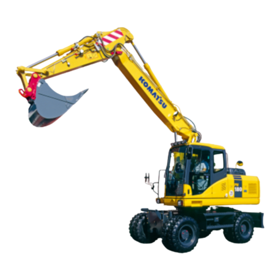
PW180-7E0
WHEELED EXCAVATOR
SERIAL NUMBER
PW180-7E0
– H55051 and up
WARNING
Unsafe use of this machine may cause serious injury or
death. Operators and maintenance personnel must
read this manual before operating or maintaining this
machine. This manual should be kept inside the cab for
reference and periodically reviewed by all personnel
who will come into contact with the machine.
Advertisement
Table of Contents

Related Manuals for Komatsu PW180-7E0


Summary of Contents for Komatsu PW180-7E0
- Page 1 Operation & VEAM400102 Maintenance Manual PW180-7E0 WHEELED EXCAVATOR SERIAL NUMBER PW180-7E0 – H55051 and up WARNING Unsafe use of this machine may cause serious injury or death. Operators and maintenance personnel must read this manual before operating or maintaining this machine.
- Page 2 PW180-7E0 – VEAM400101...
-
Page 3: Foreword
Foreword 1. Foreword PW180-7E0 – VEAM400102... -
Page 4: Foreword
Continuing improvements in the design of this machine can lead to changes in detail which may not be reflected in this manual. Consult KOMATSU or your KOMATSU distributor for the latest available information for your machine or for questions regarding information in this manual. -
Page 5: Safety Information
Safety precautions are described in "Safety (2-1)". KOMATSU cannot predict every circumstance that might involve a potential hazard in operation and maintenance. Therefore the safety message in this manual and on the machine may not include all possible safety precautions. -
Page 6: Noise Emission Levels
ISO6396 (Dynamic test method, simulated working cycle). GK018001 Sound power level emitted by the machine, measured according to ISO 6395 (Dynamic test method, simulated working cycle). This is the guaranteed value as specified in European directive 2000/14/EC. GK018002 PW180-7E0 – VEAM400102... -
Page 7: Vibration Levels
4. Use a seat that meets ISO 7096 and keep the seat main- tained and adjusted Adjust the seat and suspension for the weight and size of the operator Wear seat belt Inspect and maintain the seat suspension and adjust- ment mechanisms PW180-7E0 – VEAM400102... - Page 8 Operate the machine only when you are in good health. Provide breaks to reduce long periods of sitting in the same posture Do not jump down from the cab or machine Do not repeatedly handle and lift loads PW180-7E0 – VEAM400102...
-
Page 9: Emergency Steering
In such a case, five brake applications can be made before exhausting the energy in the accumulators. In the event of ser- vice brake failure, the park brake can be used as an emergency brake to bring the machine to a stop. PW180-7E0 – VEAM400102... -
Page 10: Introduction
1.7 Introduction Foreword Introduction 1.7.1 Intended use This KOMATSU HYDRAULIC EXCAVATOR is designed to be used mainly for the following work: Digging Smoothing work Ditching work Loading work See the section "Work possible using hydraulic excavator (3-141)" for further details. -
Page 11: Running In Your New Machine
If the machine is used for a purpose that is not listed in this manual, KOMATSU cannot bear any responsibility for safety. All consideration of safety in such operations is the responsibility of the user. -
Page 12: Locations Of Plates, Table To Enter Serial No. And Distributor
On the top of the engine. 1.8.3 Table to enter serial no. and distributor Machine serial No. Engine serial No. Product identification number Manufacturer’s name KOMATSU Hanomag GmbH Address Hanomagstr. 9 D-30449 Hannover Germany Distributor Address Phone 1-10 PW180-7E0 – VEAM400102... -
Page 13: Machine Serial Plates
Foreword 1.8 Locations of plates, table to enter serial no. and distributor 1.8.4 Machine serial plates Model Serial number Manufacturing year Weight Engine power Product Identification Number Manufactured by KOMATSU Hanomag GmbH for KOMATSU Ltd. 1-11 PW180-7E0 – VEAM400102... -
Page 14: Table Of Contents
Electromagnetic interference..........2-10 1-12 PW180-7E0 – VEAM400102... - Page 15 Use of lighting............2-32 1-13 PW180-7E0 – VEAM400102...
- Page 16 Lifting capacity chart PW180-7E0 ........
- Page 17 3.19 Tool box (chassis) ............3-90 1-15 PW180-7E0 – VEAM400102...
- Page 18 One touch power max switch ......... . . 3-134 1-16 PW180-7E0 – VEAM400102...
- Page 19 3.29 Precautions on particular jobsites..........3-170 1-17 PW180-7E0 – VEAM400102...
- Page 20 Grease............. . 4-10 Carrying out KOWA (KOMATSU Oil Wear Analysis) ......4-10 KOWA analysis items .
- Page 21 Check fan belt tension, adjust tension ........4-73 Check, adjust tension of air conditioner compressor belt..... . . 4-74 1-19 PW180-7E0 – VEAM400102...
- Page 22 Procedure for bleeding air ..........4-105 1-20 PW180-7E0 – VEAM400102...
- Page 23 Hydraulic excavator with multipurpose crane....... . 6-37 1-21 PW180-7E0 – VEAM400102...
- Page 24 Notes ............8-1 1-22 PW180-7E0 – VEAM400102...
-
Page 25: Safety
WARNING: For reasons of safety, always follow these safety precautions 2. Safety WARNING Read and follow all safety precautions. Failure to do so may result in seri- ous injury or death. This safety section also contains precautions for optional equipment and attach- ments. PW180-7E0 – VEAM400102... -
Page 26: General Precautions
Check also that there is no one near the machine. GK018007 Driving in pins, see "Replacement and inversion of bucket (3-143)". Cleaning of air cleaner element, see "When required (4-33)" in service procedure. PW180-7E0 – VEAM400102... -
Page 27: Unauthorised Modification
KOMATSU can create hazards. Before making a modification, consult your KOMATSU dis- tributor. KOMATSU will not be responsible for any injury or damage caused by any unauthorised modification. Always apply (raise) safety lock lever when leaving operator’s seat When standing up from the operator’s seat, always raise the safety lock lever to the LOCK position. -
Page 28: Always Chock The Wheels Before Going Under The Machine
If grasping the door handrail when mounting or dismounting or moving on the chassis steps, open and lock the door securely in the open position. Otherwise, the door may move suddenly, causing you to lose balance and fall. PW180-7E0 – VEAM400102... -
Page 29: Fire Prevention For Fuel And Oil
Tighten all fuel and oil caps securely. Refuelling and oiling should be carried out in well ventilated areas. GK018014 Keep oil and fuel in a secure place and do not allow unau- thorised persons to enter. GK018015 PW180-7E0 – VEAM400102... -
Page 30: Precautions When Handling At High Temperatures
Do not allow other persons to approach during the operation. Always observe the rules and regulations for the work site and environmental standards. This machine does not use asbestos, but there is a danger that imitation parts may contain asbestos, so always use genuine KOMATSU parts. PW180-7E0 – VEAM400102... -
Page 31: Crushing Or Cutting Prevention
Provide a first aid kit at the storage point. Know what to do in the event of a fire. Be sure you know the phone numbers of persons you should contact in case of an emergency. GK018019 PW180-7E0 – VEAM400102... -
Page 32: Protection Against Falling Or Flying Objects
The above comments are made with regards to typical working conditions. By all means you should put on other guards if required by conditions at your particular site. For details of safety guards, please contact your KOMATSU dis- tributor. GK018021 Also, even for other types of work, if there is any danger of being hit by falling or flying objects or of objects entering the operator’s... -
Page 33: Precautions For Attachments
Do not use attachments that are not authorised by KOMATSU or your KOMATSU distributor. Use of unautho- rised attachments could create a safety problem and adversely affect the proper operation and useful life of the machine. -
Page 34: Emergency Exit
When the machine is operated on or beside a road, a rotating beacon is required to avoid a traffic accident. Contact your KOMATSU distributor to install beacon lamp. Electromagnetic interference When this machine is operating close to a source of high elec- tromagnetic interference, such as a radar station, some abnor- mal phenomena may be observed. -
Page 35: Precaution During Operation
Check fuel, lubrication, and hydraulic systems for leaks. Have any leaks repaired. Wipe up any excess oil, fuel or other flammable fluids. Check point, see "Walk-around check (3-96)". Be sure a fire extinguisher is present and working. 2-11 PW180-7E0 – VEAM400102... -
Page 36: In Operator's Cab
If any glass is broken, replace it with a new part. Check that the head lamps and working lamps are installed to match the operating conditions. Check also that they light up properly. 2-12 PW180-7E0 – VEAM400102... -
Page 37: Operating Machine
Before operating the travel pedal, check the direction of the under carriage. If the fixed axle is at the front, the forward/neutral/reverse lever and steering will function in the opposite direction. Fixed axle Oscillating axle Travel operations, see "Walk-around check (3-96)". 2-13 PW180-7E0 – VEAM400102... -
Page 38: Check That No One Is In The Area Before Swinging Or Travelling In Reverse
Make use of all mirrors to ensure that the area around the machine is clear. There are blind spots behind the machine, so if necessary, swing the upper structure to check that there is no one behind the machine before travelling in reverse. 2-14 PW180-7E0 – VEAM400102... -
Page 39: Precautions When Travelling
Never travel over obstacles which make the machine tilt strongly (10° or more). 2-15 PW180-7E0 – VEAM400102... -
Page 40: Travelling On Slopes
Do not travel up and down on grass, fallen leaves, or wet steel plates. These materials may allow the machine to slip. Keep travel speed very low on such materials, even on flat ground. Incorrect Correct 2-16 PW180-7E0 – VEAM400102... -
Page 41: Prohibited Operations
Do not carry out deep digging under the front of the machine. Incorrect The ground under the machine may collapse and cause the machine to fall. 2-17 PW180-7E0 – VEAM400102... -
Page 42: Do Not Go Close To High-Voltage Cables
Stop operations if the visibility is poor, such as in mist, snow, or rain, and wait for the weather to improve to a condition that allows the operation to be carried out safely. 2-18 PW180-7E0 – VEAM400102... -
Page 43: Operate Carefully On Snow
Do not hit the operator cab (for two piece boom only) When the second boom cylinder is retracted, the bucket or the attachment can hit the operator cab or chassis. Operate work equipment slowly and carefully to avoid any injury and damage. Incorrect 2-19 PW180-7E0 – VEAM400102... -
Page 44: Operations On Slopes
Before leaving the operator’s compartment, always raise the safety lock lever to lock the work equipment controls. Places to lock, see "Locking (3-146)". 2-20 PW180-7E0 – VEAM400102... -
Page 45: Transportation
When shipping the machine on a hauling vehicle, obey all state and local laws governing the weight, width, and length of a load. Also obey all applicable traffic regulations. Determine the shipping route while taking into account the width, height and weight of the load. 2-21 PW180-7E0 – VEAM400102... -
Page 46: Battery
Flammable hydrogen gas is generated when the battery is charged, so remove the battery from the chassis, take it to a well-ventilated place, and remove the battery caps before charging it. Tighten the battery caps securely. Install the battery securely to the determined place. 2-22 PW180-7E0 – VEAM400102... -
Page 47: Starting With Booster Cables
When connecting the ground cable to the frame of the machine to be started, be sure to connect it as far away as possible from the battery. Starting with booster cables, see "Discharged battery (3-171)". 2-23 PW180-7E0 – VEAM400102... -
Page 48: Towing
Turn park brake release bolt (B) 180 degrees so that indicator mark is located at the top position. WARNING Operator must not operate the travel system (i.e rotate the travel motor) when the transmission disengagement pin is rotated to towing position. 2-24 PW180-7E0 – VEAM400102... -
Page 49: Bucket With Hook Or Bucket Link With Lifting Eye
(see page 2-68). Reconsider the planned lifting operation to prevent the over- load caution from sounding. If it is essential to lift to the max- imum capacity of the machine consult your KOMATSU dealer for advice Special hook When carrying out lifting work, a special lifting hook or lifting eye is necessary. - Page 50 When performing lifting operation, never raise or lower a person. No persons shall be permitted to enter the working area Due to the possible danger of the load falling or of collision with the load, no persons shall be allowed in the working area. 2-26 PW180-7E0 – VEAM400102...
- Page 51 Handling of wire ropes etc. Wear leather gloves when handling wire ropes. Protecting eyes Some oils and fluids can damage eyes. Refer to manufactured data sheet for handling and storage instructions. 2-27 PW180-7E0 – VEAM400102...
-
Page 52: Precautions For Lifting Operation
Apply the service brakes or park brake. Never lift a person. Operating posture If the machine posture is not correct, the wire ropes or ring may detach from the hook. Confirm that the hook angle is correct to avoid this. 2-28 PW180-7E0 – VEAM400102... -
Page 53: Handling Of Fluids
PTO, transmission axles and hubs avoid pro- longed or frequent contact with skin. Refer to manufacturers data sheet for handling and storage precautions. Handling of fluids For antifreeze and grease refer to manufacturers data sheet for handling and storage precautions. 2-29 PW180-7E0 – VEAM400102... -
Page 54: Precautions For Maintenance
Attach additional warning tags around the machine, if necessary. These tags are available from your KOMATSU distributor. (Part no. 20E-00-K1340) Proper tools Use only tools suited to the task. Using damaged, low quality, faulty, or makeshift tools could cause personal injury. -
Page 55: Stop The Engine Before Carrying Out Inspection And Maintenance
Rules to follow when adding fuel or oil Spilt fuel and oil may cause you to slip, so always wipe it up immediately. Always tighten the cap of the fuel and oil fillers securely. Never use fuel for washing any parts. GK018058 2-31 PW180-7E0 – VEAM400102... -
Page 56: Radiator Water Level
Slowly loosen the caps to relieve pressure before removing the caps. GK018016 Use of lighting When checking fuel, oil, coolant, or battery electrolyte, always use lighting with anti-explosion specifications. If such lighting equipment is not used, there is danger of explo- sion. GK018060 2-32 PW180-7E0 – VEAM400102... -
Page 57: During Maintenance
If water gets into the electrical system, there is danger that the machine may not move or may move unexpectedly. Do not use water or steam to clean the sensors, connectors, or the inside of the operator’s compartment. GK018063 2-33 PW180-7E0 – VEAM400102... -
Page 58: Precautions With Battery
GK018065 If you are hit by a jet of high-pressure oil, consult a doctor immediately for medical attention. GK018066 2-34 PW180-7E0 – VEAM400102... -
Page 59: Precautions When Carrying Out Maintenance At High Temperature Or
Always put oil drained from your machine in containers. Never drain oil directly on the ground. Obey appropriate laws and regulations when disposing of harmful materials such as oil, fuel, coolant, solvent, filters, batteries, and others. GK018068 2-35 PW180-7E0 – VEAM400102... -
Page 60: Position For Attaching Safety Labels
There are other labels in addition to the safety labels listed as follows, so handle them in the same way. Safety labels are available from your KOMATSU distributor. 2.4.1 Position for attaching safety labels 2-36 PW180-7E0 –... - Page 61 Follow instructions and warnings in the manuals and labels on the machine. Keep this manual in the machine cab, near operator. If this manual is lost, please contact KOMATSU distributor for replacement. Always raise safety lock lever when leaving operators seat.
- Page 62 Be sure no one is on or near machine or in the swing area. Rotate cab for full view of travel path if it can be done safely. Use spotter if view is obstructed. Follow above even if machine equipped with travel alarm and mirrors. 2-38 PW180-7E0 – VEAM400102...
- Page 63 Be sure no one is on or near machine or in the swing area. Rotate cab for full view of travel path if it can be done safely. Use spotter if view is obstructed. Follow above even if machine equipped with travel alarm and mirrors. 2-39 PW180-7E0 – VEAM400102...
- Page 64 Do not ride on machine when it is moving. 10. Stop engine warning. (20E-00-K1310) Do not open cover while engine is running. 11. Front window lock warning. This is located on the rear win- dow. (09803-A0481) Always lock window in raised or lowered position. 2-40 PW180-7E0 – VEAM400102...
- Page 65 15. Red reflector (20G-47-K1690) 16. (20Y-00-K2220) Emergency exit Read operation manual before operation 17. Travel Height -UK spec only. This is fitted to the top right hand corner of the front window. (20E-00-K1720) 2-41 PW180-7E0 – VEAM400102...
- Page 66 The machine may tip if the machine slewed when no work equipment is fitted. WARNING Failure to follow these safety precautions may lead to a serious accident. 2-42 PW180-7E0 – VEAM400102...
- Page 67 WARNING: For reasons of safety, always follow these safety precautions 21. Caution for use of hydraulic quick coupler piping system. (20J-00-11270) There is a danger of an exposed person being killed by a falling attachment Read the manual for safe operation. 2-43 PW180-7E0 – VEAM400102...
-
Page 68: Lifting Capacity Chart Pw180-7E0
2.5 Lifting capacity chart PW180-7E0 Safety WARNING: For reasons of safety, always follow these safety precautions Lifting capacity chart PW180-7E0 2.5.1 One piece boom – Lift capacity tables for 2.5 metre undercarriage When removing bucket, linkage or cylinder, lifting capacities can be increased by their respective weights. - Page 69 Safety 2.5 Lifting capacity chart PW180-7E0 WARNING: For reasons of safety, always follow these safety precautions Reach (A) 7.5 m 6.0 m 4.5 m 3.0 m 1.5 m 7.5 m *2700 *2700 6.0 m *2450 1900 3500 2500 4.5 m...
- Page 70 2.5 Lifting capacity chart PW180-7E0 Safety WARNING: For reasons of safety, always follow these safety precautions Reach (A) 7.5 m 6.0 m 4.5 m 3.0 m 1.5 m 7.5 m *2700 *2700 6.0 m *2450 2250 *4400 2900 4.5 m...
- Page 71 Safety 2.5 Lifting capacity chart PW180-7E0 WARNING: For reasons of safety, always follow these safety precautions Reach (A) 7.5 m 6.0 m 4.5 m 3.0 m 1.5 m 7.5 m *2700 *2700 6.0 m *2450 *2450 *4400 3400 4.5 m...
- Page 72 2.5 Lifting capacity chart PW180-7E0 Safety WARNING: For reasons of safety, always follow these safety precautions Reach (A) 7.5 m 6.0 m 4.5 m 3.0 m 1.5 m 7.5 m *2700 *2700 6.0 m *2450 *2450 *4400 4400 4.5 m...
- Page 73 Safety 2.5 Lifting capacity chart PW180-7E0 WARNING: For reasons of safety, always follow these safety precautions Reach (A) 7.5 m 6.0 m 4.5 m 3.0 m 1.5 m 7.5 m *2700 *2700 6.0 m *2450 *2450 *4400 4400 4.5 m...
-
Page 74: One Piece Boom - Lift Capacity Tables For 2.75 Metre Undercarriage
2.5 Lifting capacity chart PW180-7E0 Safety WARNING: For reasons of safety, always follow these safety precautions 2.5.2 One piece boom – Lift capacity tables for 2.75 metre undercarriage When removing bucket, linkage or cylinder, lifting capacities can be increased by their respective weights. - Page 75 Safety 2.5 Lifting capacity chart PW180-7E0 WARNING: For reasons of safety, always follow these safety precautions Reach (A) MAX reach 7.5 m 6.0 m 4.5 m 3.0 m 1.5 m 7.5 m *2700 *2700 6.0 m *2450 2150 3500 2800 4.5 m...
- Page 76 2.5 Lifting capacity chart PW180-7E0 Safety WARNING: For reasons of safety, always follow these safety precautions Reach (A) MAX reach 7.5 m 6.0 m 4.5 m 3.0 m 1.5 m 7.5 m *2700 *2700 6.0 m *2450 *2450 *4400 3250 4.5 m...
- Page 77 Safety 2.5 Lifting capacity chart PW180-7E0 WARNING: For reasons of safety, always follow these safety precautions Reach (A) MAX reach 7.5 m 6.0 m 4.5 m 3.0 m 1.5 m 7.5 m *2700 *2700 6.0 m *2450 *2450 *4400 3750 4.5 m...
- Page 78 2.5 Lifting capacity chart PW180-7E0 Safety WARNING: For reasons of safety, always follow these safety precautions Reach (A) MAX reach 7.5 m 6.0 m 4.5 m 3.0 m 1.5 m 7.5 m *2700 *2700 6.0 m *2450 *2450 *4400 *4400 4.5 m...
- Page 79 Safety 2.5 Lifting capacity chart PW180-7E0 WARNING: For reasons of safety, always follow these safety precautions Reach (A) MAX reach 7.5 m 6.0 m 4.5 m 3.0 m 1.5 m 7.5 m *2700 *2700 6.0 m *2450 *2450 *4400 *4400 4.5 m...
-
Page 80: Two Piece Boom - Lift Capacity Tables For 2.5 Metre Undercarriage
2.5 Lifting capacity chart PW180-7E0 Safety WARNING: For reasons of safety, always follow these safety precautions 2.5.3 Two piece boom – Lift capacity tables for 2.5 metre undercarriage When removing bucket, linkage or cylinder, lifting capacities can be increased by their respective weights. - Page 81 Safety 2.5 Lifting capacity chart PW180-7E0 WARNING: For reasons of safety, always follow these safety precautions Reach (A) 7.5 m 6.0 m 4.5 m 3.0 m 1.5 m 7.5 m *2950 2700 *4800 4200 6.0 m *2550 1800 3500 2450...
- Page 82 2.5 Lifting capacity chart PW180-7E0 Safety WARNING: For reasons of safety, always follow these safety precautions Reach (A) 7.5 m 6.0 m 4.5 m 3.0 m 1.5 m 7.5 m *2950 *2950 *4800 *4800 6.0 m *2550 2150 *4650 2900...
- Page 83 Safety 2.5 Lifting capacity chart PW180-7E0 WARNING: For reasons of safety, always follow these safety precautions Reach (A) 7.5 m 6.0 m 4.5 m 3.0 m 1.5 m 7.5 m *2950 *2950 *4800 *4800 6.0 m *2550 2550 *4650 3350...
- Page 84 2.5 Lifting capacity chart PW180-7E0 Safety WARNING: For reasons of safety, always follow these safety precautions Reach (A) 7.5 m 6.0 m 4.5 m 3.0 m 1.5 m 7.5 m *2950 *2950 *4800 *4800 6.0 m *2550 *2550 *4650 4400...
- Page 85 Safety 2.5 Lifting capacity chart PW180-7E0 WARNING: For reasons of safety, always follow these safety precautions Reach (A) 7.5 m 6.0 m 4.5 m 3.0 m 1.5 m 7.5 m *2950 *2950 *4800 *4800 6.0 m *2550 *2550 *4650 *4650...
-
Page 86: Two Piece Boom - Lift Capacity Tables For 2.75 Metre Undercarriage
2.5 Lifting capacity chart PW180-7E0 Safety WARNING: For reasons of safety, always follow these safety precautions 2.5.4 Two piece boom – Lift capacity tables for 2.75 metre undercarriage When removing bucket, linkage or cylinder, lifting capacities can be increased by their respective weights. - Page 87 Safety 2.5 Lifting capacity chart PW180-7E0 WARNING: For reasons of safety, always follow these safety precautions Reach (A) MAX reach 7.5 m 6.0 m 4.5 m 3.0 m 1.5 m 7.5 m *2950 *2950 *4800 4750 6.0 m *2550 2100...
- Page 88 2.5 Lifting capacity chart PW180-7E0 Safety WARNING: For reasons of safety, always follow these safety precautions Reach (A) MAX reach 7.5 m 6.0 m 4.5 m 3.0 m 1.5 m 7.5 m *2950 *2950 *4800 *4800 6.0 m *2550 2450...
- Page 89 Safety 2.5 Lifting capacity chart PW180-7E0 WARNING: For reasons of safety, always follow these safety precautions Reach (A) MAX reach 7.5 m 6.0 m 4.5 m 3.0 m 1.5 m 7.5 m *2950 *2950 *4800 *4800 6.0 m *2550 *2550...
- Page 90 2.5 Lifting capacity chart PW180-7E0 Safety WARNING: For reasons of safety, always follow these safety precautions Reach (A) MAX reach 7.5 m 6.0 m 4.5 m 3.0 m 1.5 m 7.5 m *2950 *2950 *4800 *4800 6.0 m *2550 *2550...
- Page 91 Safety 2.5 Lifting capacity chart PW180-7E0 WARNING: For reasons of safety, always follow these safety precautions Reach (A) MAX reach 7.5 m 6.0 m 4.5 m 3.0 m 1.5 m 7.5 m *2950 *2950 *4800 *4800 6.0 m *2550 *2550...
-
Page 92: Overload Caution
If lifting to the full capacity of the machine is required it is neces- sary to fit a full overload caution system (with work equipment position sensing to the machine.) Decal showing lifting loads (in kg) at overload warning. 2-68 PW180-7E0 – VEAM400102... -
Page 93: Monoboom - Overload Caution
Safety 2.6 Overload caution WARNING: For reasons of safety, always follow these safety precautions 2.6.1 Monoboom – Overload caution 2.6.2 Two piece boom – Overload caution 2-69 PW180-7E0 – VEAM400102... - Page 94 2.6 Overload caution Safety WARNING: For reasons of safety, always follow these safety precautions 2-70 PW180-7E0 – VEAM400102...
-
Page 95: Operation
Operation 3. Operation WARNING Please read and make sure that you understand the safety volume before read- ing this section. PW180-7E0 – VEAM400102... -
Page 96: General View
General view 3.1.1 General view of machine If directions are indicated in this section, they refer to the direc- tions shown by in the arrows in the diagram below. A: Front B: Rear C: Right D: Left PW180-7E0 – VEAM400102... - Page 97 Operation 3.1 General view Bucket Bucket cylinder Arm cylinder Boom Boom cylinder Undercarriage PW180-7E0 – VEAM400102...
-
Page 98: General View Of Controls And Gauges
3.1 General view Operation 3.1.2 General view of controls and gauges Left hand Right hand Right hand Left hand Front of levers Rear of levers PW180-7E0 – VEAM400102... - Page 99 3-50 Horn button see page 3-46 Clamshell rotation switch see page 3-50 F/N/R switch see page 3-49 Boom/undercarriage attachment switch see page 3-49 Breaker switch see page 3-50 Spare – Power max button see page 3-46 PW180-7E0 – VEAM400102...
-
Page 100: Explanation Of Components
3.2.1 Machine monitor Maintenance interval warning screen All lights up screen Normal operation screen GK018103 Basic check items Caution items Emergency stop items Meter display portion, pilot display portion Monitor switches PW180-7E0 – VEAM400102... -
Page 101: Basic Operation Of Machine Monitor
After displaying the maintenance interval warning screen for 30 seconds, the screen returns to the normal screen. After displaying the check before starting screen for 2 sec- onds, the screen changes to the warning screen or error screen. PW180-7E0 – VEAM400102... -
Page 102: If Any Abnormality Occurs During Operation
(1) or the error screen. After displaying warning screen (1) for 2 seconds, the screen automatically changes to warning screen (2), with exception of low brake pressure when warning screen (1) remains per- manently active. PW180-7E0 – VEAM400102... -
Page 103: Basic Check Items
This monitor (1) warns the operator that there has been a drop in the radiator water level. If the radiator water level is low, the lamp lights up red, so check the water level in the radiator and the sub-tank, and add water. GK018108 PW180-7E0 – VEAM400102... - Page 104 For details of the method of checking the maintenance interval, see "Service menu switch (3-32)". If it is desired to change the setting of the maintenance interval, GK018111 please consult your KOMATSU distributor. 3-10 PW180-7E0 – VEAM400102...
-
Page 105: Caution Items
Charge level monitor Engine oil level low Fuel level monitor Service machine – overdue Air cleaner clogging monitor Park brake Engine water temperature monitor Swing lock Hydraulic oil temperature monitor PPC lock Overload caution monitor 3-11 PW180-7E0 – VEAM400102... - Page 106 4. Engine water temperature monitor If this monitor (4) lights up white in low temperatures, carry out the warming-up operation. For details, see "Warming up operation (3-115)". Continue the warming-up operation until monitor (4) changes to green. 3-12 PW180-7E0 – VEAM400102...
- Page 107 (an audible warning is also given), if the warning is given lower the load. Refer to the lifting capacity chart for safe load, see "Lifting capacity chart PW180-7E0 (2-44)". 7. Engine oil level low When monitor (7) lights up, the engine oil level is insufficient.
- Page 108 11. PPC lock This monitor warns that the machine is travelling at high speed without applying the PPC lock switch. Push the PPC lock switch immediately when the machine is travelling at high speed. GK018123 GK018122 3-14 PW180-7E0 – VEAM400102...
-
Page 109: Emergency Stop Items
If there is an abnormality, the monitor for the abnormal location lights up red and the buzzer sounds, so carry out action immediately. Engine water temperature monitor Hydraulic oil temperature monitor Engine oil pressure monitor Low brake pressure 3-15 PW180-7E0 – VEAM400102... - Page 110 CAUTION Do not drive machine with low brake pressure warning lamp illu- minated. REMARK The color when the monitor lights up for the basic check items, caution items, and emergency stop items is as follows. 3-16 PW180-7E0 – VEAM400102...
- Page 111 Air cleaner clogging monitor – Engine water temperature monitor Green White Hydraulic oil temperature monitor Green White Engine oil pressure monitor – Overload caution monitor – Low brake pressure – Swing lock – Control lever lock – 3-17 PW180-7E0 – VEAM400102...
-
Page 112: Meter Display Portion
Working mode monitor Travel mode monitor Power max monitor Engine water temperature gauge Fuel gauge Hydraulic oil temperature gauge Service meter and clock Travel direction monitor Undercarriage attachment monitor Park brake Suspension lock Control lever lock Swing position 3-18 PW180-7E0 – VEAM400102... - Page 113 3. Auto-deceleration monitor This monitor (3) shows if the auto-deceleration function has been actuated. The monitor display when the auto-deceleration switch is oper- ated is as follows. Auto-deceleration monitor ON: Auto-deceleration actuated. Auto-deceleration monitor OFF: Auto-deceleration canceled. GK018132 3-19 PW180-7E0 – VEAM400102...
- Page 114 The digging power is increased while the knob switch is being pressed only for working modes A and E. Note that this opera- tion should be used to overcome heavy operating conditions and not for continuous use. Monitor goes out: Power max function stopped. 3-20 PW180-7E0 – VEAM400102...
-
Page 115: Meters
(1) lights up red. When indicator is between A and C the fuel level monitor (1) remains green. The correct fuel level may not be displayed for a short time when the starting switch is turned ON, but this is not an abnormality. 3-21 PW180-7E0 – VEAM400102... - Page 116 Use the time display to set the maintenance interval. When the starting switch is ON, the service meter advances even if the machine is not moving. The service meter advances by 1 for every hour of operation, GK018135 regardless of the engine speed. 3-22 PW180-7E0 – VEAM400102...
- Page 117 14. Suspension lock This monitor (14) displays the set suspension lock mode. When one of the suspension lock switches is selected the monitor dis- plays one of the following selections. Auto suspension lock mode Permanent suspension lock 3-23 PW180-7E0 – VEAM400102...
- Page 118 Operation 15. Control lever lock This lamp will illuminate when the PPC lock is switched on. GK018145 GK018144 16. Swing position This lamp (16) will illuminate when the upper structure is orien- tated to straight ahead. 3-24 PW180-7E0 – VEAM400102...
-
Page 119: Monitor Switches
Contrast adjustment switch Automatic suspension lock switch Permanent suspension lock switch Input confirmation switch Scroll down Scroll up Undo switch Rear left outrigger/blade switch Front left outrigger/blade switch Front right outrigger switch Rear right outrigger switch 3-25 PW180-7E0 – VEAM400102... - Page 120 The display on the monitor display portion changes for each mode. If you require a default setting other than "P mode" please consult your KOMATSU distributor or dealership to have the setting amended. REMARK...
- Page 121 To cancel creep speed, press Hi/Lo switch. REMARK When creep speed is selected the mode is displayed in the cen- tre of the screen for 2 seconds before returning to the normal screen display. 2 seconds 3-27 PW180-7E0 – VEAM400102...
- Page 122 REMARK Each time that the travel speed selector switch is operated, the mode is displayed in the centre of the monitor display, 2 seconds and the screen returns to the normal screen after 2 seconds. 3-28 PW180-7E0 – VEAM400102...
- Page 123 Light on switch will illuminate when active. GK018103 5. Menu select switch This switch (5) is used to select the attachment hydraulic flow setting in each of the working modes P, E, and B. GK018103 3-29 PW180-7E0 – VEAM400102...
- Page 124 (13) to adjust to the desired flow. 3. After completing the flow setting, press input confirmation switch (12). The monitor display will return to the normal screen. REMARK The flow can be adjusted for the attachment installed. 3-30 PW180-7E0 – VEAM400102...
- Page 125 6. Press up switch (14) or down switch (13) to adjust to the desired flow. 7. After completing the flow setting, press input confirmation switch (12). The monitor display will return to the normal screen. 3-31 PW180-7E0 – VEAM400102...
- Page 126 Press switch (6) to display the maintenance screen and check that there is no abnormality in any other monitor. If another monitor is lit up red on the maintenance screen, carry out maintenance for that item also. 3-32 PW180-7E0 – VEAM400102...
- Page 127 Axles 1000 If it is desired to change the setting for the maintenance interval, please contact your KOMATSU distributor. The method of checking the time remaining to maintenance is as follows. 1. Look at the maintenance screen, press up switch (14) or down switch (13) on the monitor switch portion, until required item is highlighted.
- Page 128 (12). The screen will switch to the default setting screen. 4. After checking the time on the default setting screen, press input confirmation switch (12). The screen will return to the maintenance screen. (Press back switch (15) to return to the previous screen.) 3-34 PW180-7E0 – VEAM400102...
- Page 129 This switch (8) is used to stop the alarm buzzer when it has sounded to warn of some abnormality that has occurred whilst the machine is operating. REMARK The lamp on the switch will illuminate when the warning buzzer is sounding. 3-35 PW180-7E0 – VEAM400102...
- Page 130 Front axle will be fixed in place when engaged, the permanent suspension lock indicator will illuminate. To disengage lock, press switch (11) again. REMARK Permanent suspension lock should only be used when travelling slowly. Do not use in high speed travel. GK018103 3-36 PW180-7E0 – VEAM400102...
- Page 131 Pressing up switch (14) or down switch (13) when in the menu screens will allow you to move up and down the menu options. In certain menus they can also be used to increase and decrease displayed values. (e.g. Flow in the attachment circuit) GK018103 3-37 PW180-7E0 – VEAM400102...
- Page 132 19. Rear right outrigger switch Allows operation of rear right outrigger. Light on switch illuminates when activated. Liquid crystal monitor adjustment switch Press this switch (9) to adjust the brightness and contrast of the monitor display screen. GK018103 3-38 PW180-7E0 – VEAM400102...
-
Page 133: Adjustment Screens
3. After completing adjustment of the contrast, press input con- firmation switch (12). This will store the new setting and return you to the adjustment menu. REMARK As normal, within any menu, press switch (15) to return to the previous screen at any time. 3-39 PW180-7E0 – VEAM400102... - Page 134 GK018103 Year Month Hour Minute 3. After completing adjustment of the clock, press input confir- mation switch (12). This will return you to the above menu and store the new setting. 3-40 PW180-7E0 – VEAM400102...
- Page 135 Day time/Night time. GK018103 Light blue/Dark blue Dark blue/Light blue 3. After completing adjustment of the background colour, press input confirmation switch (12). This will return you to the above menu and store the new setting. 3-41 PW180-7E0 – VEAM400102...
-
Page 136: Switches
3.4 Switches Operation Switches Left hand Right hand Right hand Left hand Front of levers Rear of levers 3-42 PW180-7E0 – VEAM400102... - Page 137 3-50 Horn button see page 3-46 Clamshell rotation switch see page 3-50 F/N/R switch see page 3-49 Boom/undercarriage attachment switch see page 3-49 Breaker switch see page 3-50 Spare – Power max button see page 3-46 3-43 PW180-7E0 – VEAM400102...
- Page 138 Then, start the engine by turning the key to the START position. Fuel control dial (with auto-deceleration mechanism) Fuel Control Dial (6) adjusts the engine speed and output. MIN (low idling): Turned fully to the left MAX (full speed) Turned fully to the right 3-44 PW180-7E0 – VEAM400102...
- Page 139 This is used to light cigarettes. To use, push the lighter in. After a few seconds it will spring back. Pull out the lighter (3) and light your cigarette. No other equipment may be connected to the cigarette lighter without the prior permission of an authorized KOMATSU distrib- utor. Swing lock switch WARNING...
- Page 140 This lights up the cab lamp. ON position: Lights up The cab lamp can be turned on even when the starting switch is at the OFF position, so be careful not to leave it on by mistake. 3-46 PW180-7E0 – VEAM400102...
- Page 141 The swing lock override switch is designed to allow operations to be carried out for a short period when there is an abnormality in the swing brake electrical system (swing brake system error). The abnormality must be repaired immediately. 3-47 PW180-7E0 – VEAM400102...
- Page 142 Park brake applied (warning light illuminated) Do not apply the park brake while the machine is in motion except in an emergency. NOTE Applying the park brake while the machine is in motion may damage the park brake. 3-48 PW180-7E0 – VEAM400102...
- Page 143 Boom/Undercarriage attachment switch Switch (37) changes the function of the right control lever between boom and undercarriage attachment operation. WARNING Lights on the undercarriage attachment select panel indicate which undercarriage attachments are in operation. Right control lever 3-49 PW180-7E0 – VEAM400102...
- Page 144 Left control lever 3-50 PW180-7E0 – VEAM400102...
- Page 145 Main beam indicator (23) will illuminate when main beam headlights are illuminated. To flash headlights pull steering column stalk fully upwards and release. 3-51 PW180-7E0 – VEAM400102...
- Page 146 When any or all of these options are fitted, all of the lights will be switched on (or off) with this switch. Lamps light up OFF: Lamps go off Heated seat switch (option) If fitted - switch (12) actuates the heated seat. Seat heated OFF: Seat not heated 3-52 PW180-7E0 – VEAM400102...
- Page 147 (25), this starts all of the indicator lights to flash on and off. This is indicated by lights in the switch (25) and the green left/right indicator display, flashing on and off together. Hazard warning lights off OFF: Hazard warning lights on 3-53 PW180-7E0 – VEAM400102...
-
Page 148: Control Levers, Pedals
3.5 Control levers, pedals Operation Control levers, pedals Left hand Right hand Right hand Left hand Front of levers Rear of levers 3-54 PW180-7E0 – VEAM400102... - Page 149 3-50 Horn button see page 3-46 Clamshell rotation switch see page 3-50 F/N/R switch see page 3-49 Boom/undercarriage attachment switch see page 3-49 Breaker switch see page 3-50 Spare – Power max button see page 3-46 3-55 PW180-7E0 – VEAM400102...
- Page 150 This device is a hydraulic lock, so even if it is in the lock position, the work equipment control lever will move, but the work equip- ment and swing motor will not work. Lock Unlock 3-56 PW180-7E0 – VEAM400102...
- Page 151 If all control levers are set to neutral, the engine speed will drop by approx. 100 rpm, and after approx. 4 seconds, the engine speed will drop to the deceleration speed (approx. 1400 rpm). 3-57 PW180-7E0 – VEAM400102...
- Page 152 The travel pedal is used in conjunction with the Forward/Neutral/ Reverse (F/N/R) switch (36) located on the right control lever. Select the direction required using F/N/R switch then depress travel pedal (20) to commence travel. Pos. Status Forward Neutral Reverse Right control lever 3-58 PW180-7E0 – VEAM400102...
- Page 153 The position of the steering column can be adjusted fore and aft by depressing pedal (1), moving column to desired position and releasing pedal (1). WARNING Steering actions will be reversed if undercarriage is facing oppo- site direction. 3-59 PW180-7E0 – VEAM400102...
- Page 154 Neutral position: Boom is stopped and held in the same position. Neutral NOTE (2) Lower On machines equipped with a monoboom this pedal is used to operate the second attachment circuit (option). CAUTION Do not rest foot on the pedal unless in use. 3-60 PW180-7E0 – VEAM400102...
-
Page 155: Front Window
3. Check that the wiper blade (A) is stored in the right frame. WARNING When the front window is open, there is danger that it will fall, so always lock it with left and right lock levers (B). 3-61 PW180-7E0 – VEAM400102... - Page 156 5. Hold lower handle (C) with your left hand from inside the operator’s cab, and with your right hand, grip top handle (D), pull it up, and firmly push it against lock catch (E) at the rear of the cab to securely lock the window. GK018199 GK018195 3-62 PW180-7E0 – VEAM400102...
- Page 157 If the arrow on lock case (F) does not line up with the arrow on lock lever (B), the lock is not properly engaged. Repeat the operation in Step 5 to engage the lock. GK018201 3-63 PW180-7E0 – VEAM400102...
-
Page 158: When Closing
4. Grip handle (C) at the bottom of the front window with your left hand and handle (D) at the top with your right hand, push the window to the front, then lower it slowly. GK018203 GK018195 3-64 PW180-7E0 – VEAM400102... -
Page 159: Removing Front Bottom Window
2. After removing the bottom window, store it at the rear of the operator’s cab and lock it securely with left and right locks (B). When removing, always hold the glass with one hand and release the lock with the other hand. GK018206 3-65 PW180-7E0 – VEAM400102... -
Page 160: Emergency Exit From Operator's Cab
An optional guard can be provided for work- ing in areas at risk from falling or flying objects. Clear rain visor The cab is fitted with a clear rain visor to prevent rainfall on the windscreen above the area cleared by the wiper. 3-66 PW180-7E0 – VEAM400102... -
Page 161: Pull Down Sun Visor
1. The door will become fixed in place when it is pressed against catch (1). 2. To release the lock, press knob (2) down at the left side of the operator’s seat to release the catch. When fixing the door, fix it firmly to the catch. 3-67 PW180-7E0 – VEAM400102... -
Page 162: Cap, Cover With Lock
GK018211 To lock the cap Type B 1. Turn the cap into place. 2. Turn the key anti-clockwise to align the match mark on the cap with the key slot. 3. Take the key out. GK018212 3-68 PW180-7E0 – VEAM400102... -
Page 163: Method Of Opening And Closing Cover With Lock (Cover With Lock)
1. Insert the key. 2. Turn it counterclockwise and open the cover by pulling the cover grip. To lock the cover 1. Close the cover and insert the key. 2. Turn the key clockwise and take the key out. 3-69 PW180-7E0 – VEAM400102... -
Page 164: Fuse
Heated seat and optional power supply (24V) 15 A RH PPC lever power 20 A Seat compressor and cab interior light Monitor, controller (regular power), 15 A starter switch 10 A Hazard warning 30 A Engine controller Engine controller 3-70 PW180-7E0 – VEAM400102... -
Page 165: Fuse Box 2
Road lights (Master fuse) 10 A Rototilt controller (1) 10 A Spare fuse 10 A Spare fuse 10 A Spare fuse Side light (LH) Side light (RH) 15 A Dipped beam 15 A Main beam 10 A Spare fuse 3-71 PW180-7E0 – VEAM400102... -
Page 166: Luggage Tray
3.12 Cup holder A cup holder is provided to the left of the operator for holding cups or cans. Drinks should not be left in the cup holder whilst operating the machine because spillage may occur. 3-72 PW180-7E0 – VEAM400102... -
Page 167: Hot And Cool Box
Ensure radio is switched off when leaving the machine for long periods to prevent draining of battery charge. NOTE Before transporting the machine or putting inside a building store the antenna to prevent any interference. Antenna storage location 3-73 PW180-7E0 – VEAM400102... -
Page 168: Power Pick-Up Port
Do not use cigarette lighter as the power source for 12V equip- ment. It will cause damage to the equipment. If the cigarette lighter is removed, it can be used as a power source. The capacity of the cigarette lighter is 85W (24V × 3.5A). 3-74 PW180-7E0 – VEAM400102... -
Page 169: Handling Air Conditioner
This switch (1) is used to stop the fan and air conditioner. When OFF switch (1) is pressed, the set temperature and air flow display on display monitor (7) and the lamps above auto switch (5) and air conditioner switch (8) go out, and operation stops. GK018232 3-75 PW180-7E0 – VEAM400102... - Page 170 The temperature can be set in stages of 0.5°C. GK018234 Monitor display and the function Monitor display (°C) Set temperature 18.0 Max. cooling Adjusts temperature inside cab to set 18.5 to 31.5 temperature 32.0 Max. heating 3-76 PW180-7E0 – VEAM400102...
- Page 171 (including defroster vent) Front and rear vents – (including defroster vent) Foot vent – Foot, foot vents Cannot be selected for automatic (including defroster vent) operation Front vents Cannot be selected for automatic (including defroster vent) operation 3-77 PW180-7E0 – VEAM400102...
- Page 172 This display monitor displays the status of temperature set- ting (a), air flow (b), and vents (c). When OFF switch (1) is pressed, the display of temperature setting (a) and air flow (b) goes out, and operation stops. GK018241 3-78 PW180-7E0 – VEAM400102...
- Page 173 Open Close Selector lever forward: To defroster (open) Selector lever back: Closed The defroster can be used when the vent selector switch is set to face or face and foot. 3-79 PW180-7E0 – VEAM400102...
-
Page 174: Method Of Operation
GK018234 REMARK When vent display monitor (c) displays (d) or (e), and the engine water temperature is low, the air flow is automatically limited to prevent cold air from blowing out. GK018246 3-80 PW180-7E0 – VEAM400102... -
Page 175: Stopping Automatic Operation
Press OFF switch (1). The displays for temperature setting (a) and air flow (b) on the display monitor, and the lamps above auto switch (5) and air conditioner switch (8) go out, and the opera- tion stops. GK018232 3-81 PW180-7E0 – VEAM400102... -
Page 176: Manual Operation
2. Turn air conditioner switch (8) ON. Check that the lamp at the top of the air conditioner switch lights up. GK018244 3. Press the temperature setting switch and adjust the temper- ature inside the cab. GK018234 3-82 PW180-7E0 – VEAM400102... -
Page 177: Stopping Manual Operation
Press OFF switch (1). The displays for temperature setting (a) and air flow (b) on the display monitor, and the lamps above auto switch (5) and air conditioner switch (8) go out, and the opera- tion stops. GK018232 3-83 PW180-7E0 – VEAM400102... -
Page 178: Operation With Cold Air To Face And Warm Air To Feet
3. Turn air conditioner switch (8) ON. When this is done, check that the lamp above the air conditioner switch lights up. GK018244 4. Adjust fan switch (2), temperature setting switch (3) and FRESH/RECIRC selector switch (6) to the desired positions. GK018248 3-84 PW180-7E0 – VEAM400102... -
Page 179: Defroster Operation
GK018233 GK018241 2. Press vent selector switch (4) and set the vent display on the display monitor to the display shown in (f) or (g) in the dia- gram on the right. GK018235 GK018249 3-85 PW180-7E0 – VEAM400102... - Page 180 (Vents (C) and (D1) are fixed and cannot be adjusted.) NOTE When operating in the rain or when it is desired to remove the mist from the window glass or to dehumidify the air, turn air con- ditioner switch (8) ON. GK018244 3-86 PW180-7E0 – VEAM400102...
-
Page 181: Precautions When Using Air Conditioner
When the cooler is on, set the temperature so that it feels slightly cool when entering the cab (5 - 6°C) lower than the outside tem- perature). This temperature difference is considered to be the most suitable for your health. Adjust the temperature properly. 3-87 PW180-7E0 – VEAM400102... -
Page 182: Check, Maintain Machine Equipped With Air Conditioner
After completing the troubleshooting, press OFF switch (1) again to return to the normal display. If any abnormality is detected by the self-diagnostic function, ask your KOMATSU distributor to carry out inspection and repair. 3-88 PW180-7E0 – VEAM400102... -
Page 183: Switch Set Temperature Display Between °F And °C
5 seconds while the fan is running, the temperature display will switch between °F and °C. (Note that the unit is not displayed.) Liquid crystal display range GK018234 °C 18.0 to 32.0 °F 63 to 91 3-89 PW180-7E0 – VEAM400102... -
Page 184: Fusible Link
Never splash or spill water, mud or drink over the controller as this may cause a fault. If a fault occurs in the controller do not attempt repair. Con- sult your KOMATSU distributor. 3.19 Tool box (chassis) This is used for storage of tools. -
Page 185: Refuelling Pump
8. Switch on the pump (switch B). 9. Check that the pump primes properly (should prime within 1 minute). If it does not, stop the pump and check that the strainer is clean and hose is immersed in the fuel. 3-91 PW180-7E0 – VEAM400102... -
Page 186: Maintenance
Check hose joints, electrical cables and clean the pump body of impurities. Storage: If the pump is not to be used for a period, ensure that fuel is sprayed into the motor housing every two weeks to prevent risk of rusting to the rotor. 3-92 PW180-7E0 – VEAM400102... -
Page 187: Warning Lamps
(25), this starts all of the indicator lights to flash on and off. This is indicated by lights in the switch (25) and the green left/right indicator display, flashing on and off together. Hazard warning lights off OFF: Hazard warning lights on 3-93 PW180-7E0 – VEAM400102... -
Page 188: Handling Accumulators
The accumulator is installed to the position shown in the dia- gram on the right. 3-94 PW180-7E0 – VEAM400102... -
Page 189: Clutch Control Accumulator (B)
Special accumulator (Italian regulations) (C) × 4 for machines supplied to Italy four brake circuit accumulators are installed. An additional accumulator (C) is required for machines destined for the italian domestic market. The additional accumulator is required to meet italian braking regulations. 3-95 PW180-7E0 – VEAM400102... -
Page 190: Operation
Check carefully, and if any abnormality is found, always repair it or contact your KOMATSU distributor. Before starting the engine, look around the machine and under the machine to check for loose nut or bolts, or leakage of oil, fuel, or coolant, and check the condition of the work equipment and hydraulic system. - Page 191 9. Check lifting eye for damage Check the lifting eye (or hook and safety latch) for damage. If damage is found, contact your KOMATSU distributor for repair. 10. Check seat belt and mounting clamps Check there is no abnormality in the seat belt or mounting clamps.
-
Page 192: Check Before Starting
FULL level. Full 2. After adding water, tighten the cap securely. 3. If the reserve tank becomes empty, first inspect for water leaks and then fill the radiator and the reserve tank with water. 3-98 PW180-7E0 – VEAM400102... -
Page 193: Check Oil Level In Engine Oil Pan, Add Oil
Ensure the machine is level when checking oil level and wait 15 minutes after stopping engine before checking the oil level. WARNING Allow the engine to cool before checking the oil level to avoid burns by touching hot engine parts. 3-99 PW180-7E0 – VEAM400102... -
Page 194: Check Fuel Level, Add Fuel
(4-16)". GK018263 REMARK If breather holes (1) on the cap is clogged, the pressure in the tank will drop and fuel will not flow. Clean the holes from time to time. 3-100 PW180-7E0 – VEAM400102... -
Page 195: Check Oil Level In Hydraulic Tank, Add Oil
The oil level will vary depending upon the oil temperature. Accordingly, use the following as a guide: Before operation: Around midway between H and L (Oil temperature 10 to 30°C) Normal operation: Around H level (Oil temperature 50 to 80°C) 3-101 PW180-7E0 – VEAM400102... -
Page 196: Check Air Cleaner For Clogging
If the fuses frequently blow, if there are traces of short cir- cuits in the electrical wiring, locate the cause immediately and carry out repairs, or contact your KOMATSU distributor for repairs. Keep the top surface of the battery clean and check the breather hole in the battery cap. -
Page 197: Check Function Of Horn
2. Confirm that the horn sounds without delay when the horn button is pressed. If the horn does not sound, ask your KOMATSU distributor for repair. Check for water and sediment in water separator, drain water 1. Open the pump room door on the right side of the machine. - Page 198 If transparent cap (2) is dirty and the contents cannot be easily seen, clean transparent cap (2) when replacing the fil- ter. When washing, if drain valve (3) is removed, coat the O-ring with grease, then tighten by hand until it contacts bottom 3-104 PW180-7E0 – VEAM400102...
-
Page 199: Adjustment Of Operator's Seat (Air Suspension Seat)
E – Adjustment of tilting seat angle To adjust the tilt of the seat lift left hand handle (5). By exerting pressure on or off the seat it can be moved to the desired angle position. 3-105 PW180-7E0 – VEAM400102... - Page 200 I – Seat depth adjustment To adjust the depth of the seat cushion, lift the right hand handle (9). By moving the seat cushion backwards or forwards the desired seating position can be reached. 3-106 PW180-7E0 – VEAM400102...
-
Page 201: Rearview Mirrors
Adjust the mirror so a point 1000 mm to the right of the machine, 1000 mm in front of the machine and 1500 mm above the ground can just be seen from the edge of the mirror (see diagram). 3-107 PW180-7E0 – VEAM400102... -
Page 202: Seat Belt
Pull the belt lightly to check that it is properly locked. GK018285 Removing seat belt Press button (5) in buckle (4), and remove tongue (3) from the buckle (4). The belt is automatically spooled, hold grip (2) and return the belt slowly to the retractor (1). 3-108 PW180-7E0 – VEAM400102... -
Page 203: Adjustment Of Operator's Seat (Mechanical Seat)
H – Height adjustment For details, see "H – Height adjustment (3-106)". I – Seat depth adjustment For details, see "I – Seat depth adjustment (3-106)". Seat belt For details, see "Seat belt (3-108)". 3-109 PW180-7E0 – VEAM400102... -
Page 204: Operations And Checks Before Starting Engine
Lock Unlock 2. Select neutral on the right control lever (4). Forward Neutral Reverse Right control lever 3-110 PW180-7E0 – VEAM400102... - Page 205 If the monitors or gauges do not light up or the buzzer does not sound, there is probably a broken bulb or disconnection in the monitor wiring, so contact your KOMATSU distributor for repairs. After approx. 3 sec., the following gauges will remain on and the other monitors will go out.
-
Page 206: Starting Engine
2. Turn the key in starting switch (5) to the START position. The engine will start. Heat Start 3. When the engine starts, release the key in starting switch. The key will return automatically to the ON position. Heat Start 3-112 PW180-7E0 – VEAM400102... -
Page 207: Starting In Cold Weather
The monitor and gauge also light up when the key is at the HEAT position, but this does not indicate any abnormality. If the temperature is low, the monitor screen may become dark or it may take time for the display to appear. This is normal. 3-113 PW180-7E0 – VEAM400102... -
Page 208: Operations And Checks After Starting Engine
Particularly in cold areas, be sure to carry out the warming-up operation fully. 3-114 PW180-7E0 – VEAM400102... -
Page 209: Warming Up Operation
5 minutes with no load. 2. Lower the safety lock lever (16) to the UNLOCK position, switch OFF the control lever lock switch and raise the bucket from the ground. GK018291 Control lever lock switch Lock Unlock 3-115 PW180-7E0 – VEAM400102... - Page 210 NOTE When the work equipment is retracted, take care that it does not interfere with the machine body or ground. Left control lever Left swing Right swing 3-116 PW180-7E0 – VEAM400102...
- Page 211 6. Check that there is no abnormal exhaust gas colour, noise, or vibration. If any abnormality is found, repair it. 7. Press power mode select on the monitor panel until the lamp of the mode to be used lights up. 3-117 PW180-7E0 – VEAM400102...
-
Page 212: In Cold Areas (Automatic Warming-Up Operation)
1. Set fuel control dial (6) at the low idling (MIN) position and run the engine for about 5 minutes without load. 3-118 PW180-7E0 – VEAM400102... - Page 213 When pulling in the work equipment, be careful not to let it hit the chassis or ground. 7. Turn fuel control dial to the full speed (MAX) position and carry out the operation in Step 6 for 3 - 5 minutes. 3-119 PW180-7E0 – VEAM400102...
- Page 214 If it becomes necessary in an emergency to lower the engine speed to low idling, cancel the automatic warming-up opera- tion as follows. 1. Turn fuel control dial to the full speed (MAX) position and hold it for 3 seconds. 3-120 PW180-7E0 – VEAM400102...
- Page 215 Operation 3.23 Operation 2. When fuel control dial is returned to the low idling (MIN) position, the engine speed will drop. 3-121 PW180-7E0 – VEAM400102...
-
Page 216: Moving Machine Off
1. Set swing lock switch (10) to the ON (actuated) position and confirm that swing lock monitor lamp lights up. GK018297 2. Turn fuel control dial (6) to the min. idling position, engine speed is controlled automatically. 3-122 PW180-7E0 – VEAM400102... - Page 217 Hi mode is for high speed travel, on smooth surfaces with slopes up to 5 degrees. Auto mode: for travelling on roads or job sites with varying terrain. WARNING Do not use auto mode on steep downhill slopes - use Lo mode 3-123 PW180-7E0 – VEAM400102...
- Page 218 REMARK When travelling in Auto mode a slight shock may occasion- ally be heard and/or felt as the automatic transmission clutch operates. This is normal. 3-124 PW180-7E0 – VEAM400102...
-
Page 219: 3.23.10 Steering
Failure to comply with this notice will result in severe dam- age to the transmission unit. If you are uncertain about how to tow the machine, please contact your local KOMATSU distributor for advice. 3-125 PW180-7E0 – VEAM400102... -
Page 220: 3.23.11 Travelling On Public Highway
Failure to comply with this notice will result in severe dam- age to the transmission unit. If you are uncertain about how to tow the machine, please contact your local KOMATSU distributor for advice 3-126 PW180-7E0 – VEAM400102... -
Page 221: 3.23.12 Stopping And Parking
‘latches’). 2. Select neutral on right control lever (4). 3. When parking, lower the work equipment until it touches the ground. Forward Neutral Reverse Right control lever 3-127 PW180-7E0 – VEAM400102... -
Page 222: Stopping Machine (Emergency)
Failure to comply with this notice will result in severe dam- age to the transmission unit. If you are uncertain about how to tow the machine, please contact your local KOMATSU distributor for advice. 3-128 PW180-7E0 – VEAM400102... -
Page 223: Swinging (Slewing The Upper Carriage)
2. Operate left work equipment control lever (17) to swing the upper structure. 3. When not operating the swing, turn swing lock switch (10) ON (ACTUATED) 4. Before travelling re-apply swing lock brake. Swing left Swing right Left control lever 3-129 PW180-7E0 – VEAM400102... -
Page 224: 3.23.14 Operation Of Work Equipment
Swing operation position for 4 seconds, even if the fuel control dial is set to FULL, Swing Swing the auto-deceleration mechanism will act to reduce the engine left right speed to auto-decel speed. Left control lever 3-130 PW180-7E0 – VEAM400102... - Page 225 Bucket operation Curl Dump Right control lever Hydraulic adjust boom operation: Hydraulic adjust boom pedal Depress front of pedal (29) to extend the boom and the rear of the pedal to retract the boom. Lower Raise 3-131 PW180-7E0 – VEAM400102...
-
Page 226: Operation Of Dozer And Outriggers
Lever back – Attachment up 4. To return right control lever to boom operation activate switch (37). Symbol (12) will now disappear from the monitor panel display WARNING When moving the machine, confirm that the chassis attachment is raised. 3-132 PW180-7E0 – VEAM400102... -
Page 227: Precautions For Using The Dozer
3. Ensure that suspension lock system is fully free when required for dozing operations. See "Automatic suspension lock switch (3-36)". REMARK Dozer blade is to be used only for stabilizing and light doz- ing. 3-133 PW180-7E0 – VEAM400102... -
Page 228: 3.23.15 Working Mode Selection
This function is not actuated when the working mode is set to L mode or B mode. CAUTION Continuous use of this facility will raise the hydraulic oil tempera- ture above normal. GK018310 Left control lever 3-134 PW180-7E0 – VEAM400102... -
Page 229: 3.23.16 Prohibitions For Operation
Do not use the dropping force of the bucket as a pickaxe, breaker, or pile driver. This will bring excessive force to bear on the structure of the machine, and will not only damage the machine, but is also dangerous. 3-135 PW180-7E0 – VEAM400102... - Page 230 Do not use the dropping force of the machine for digging. Incorrect Digging rocky ground It is better to excavate hard rocky ground after breaking it up by some other means. This will not only reduce damage to the machine but make for better economy. 3-136 PW180-7E0 – VEAM400102...
-
Page 231: 3.23.17 Precautions For Operation
Front axle of machine must be locked as machine will become unstable. REMARK Precautions when using the work equipment. Do not use the park brake to reduce movement of the machine when using work equipment. This will result in premature failure of the park brake. 3-137 PW180-7E0 – VEAM400102... -
Page 232: 3.23.18 Recommendations For Travelling
7. Travel over longer distances (e.g. on public roads) at adjusted (medium) speed. 8. Disable the service brake lock (if installed). If the service brake pedal is the alternative type, see "Brake pedal (3-59)" disable the lock. 3-138 PW180-7E0 – VEAM400102... -
Page 233: 3.23.19 Precautions When Travelling Up Or Down Hills
90°-100° and lower the engine speed. 3. When travelling up a steep hill of more than 15°, set the work Uphill equipment in the posture shown in the diagram on the right. 90°-100° 3-139 PW180-7E0 – VEAM400102... -
Page 234: 3.23.20 How To Escape From Mud
If you are uncertain about how to tow the machine, please contact your local KOMATSU distributor for advice. 3.23.20 How to escape from mud Always operate carefully to avoid getting stuck in mud. If the ma- chine does get stuck in mud, use the following procedures to get the machine out. -
Page 235: 3.23.21 Work Possible Using Hydraulic Excavator
To excavate a wide ditch, first dig out both sides and then finally remove the center portion. 3-141 PW180-7E0 – VEAM400102... -
Page 236: Loading Work
Loading is easier and capacity greater if you begin from the front of the dump truck body than if loading is done from the side. Levelling work Can be carried out with work equipment or dozer blade (option). 3-142 PW180-7E0 – VEAM400102... -
Page 237: 3.23.22 Replacement And Inversion Of Bucket
3. Align the arm with holes (1) and the link with holes (2), then install pins (A) and (B). 3-143 PW180-7E0 – VEAM400102... -
Page 238: Inversion
3-144 PW180-7E0 – VEAM400102... -
Page 239: 3.23.23 Stopping Engine
4. Check the engine compartment for paper and debris. Clean out any paper and debris to avoid a fire hazard. 5. Remove any mud stuck to the undercarriage. REMARK It is normal for water to drip from aircon drain hoses under the cab. 3-145 PW180-7E0 – VEAM400102... -
Page 240: 3.23.24 Check After Stopping Engine
On machines fitted with twin wheel assemblies a valve extension is fitted to the inner wheel to facilitate deflation. This part should always be refitted following disassembly as it ensures that the inner wheel assembly can be deflated whilst fitted to the hub. 3-146 PW180-7E0 – VEAM400102... - Page 241 WARNING Failure to observe the following procedure may result in serious injury or death. 3. Twin wheel assembly – 3 part rim Rim Base Loose flange Lockring Rim Gutter (groove) Fig. 1 3-147 PW180-7E0 – VEAM400102...
- Page 242 WARNING It is essential that the lock-ring is seated correctly. Put the wheel assembly into a safety cage and inflate the tyre to a pressure of 1 - 1.5 bar. Fig. 2 3-148 PW180-7E0 – VEAM400102...
- Page 243 4. Twin wheel assembly – 2 part rim Fig. 4 Some KOMATSU machines are fitted with a 2 piece wheel rim of the type shown in Fig. 5. In this case the loose flange and lock- ring are replaced by a single split flange.
- Page 244 If the fixing nuts or hub studs show signs of wear or corro- sion they must be replaced. 5. Wheel spacer WARNING Wheel spacers must not be used with radial ply tyres. 6. Rotating tyres Consult your local KOMATSU distributor for advice on rotating tyres. 3-150 PW180-7E0 – VEAM400102...
-
Page 245: Transportation
Always check that the door on the cab is locked, regardless of whether it is open or closed. Do not open or close the door on ramps or on a platform. Max. 15° This may cause a sudden change in the operating force. GK018338 3-151 PW180-7E0 – VEAM400102... - Page 246 3. Turn the auto-deceleration switch OFF, and return the fuel control dial (6) to reduce the engine speed. For details, see "Auto-deceleration switch (3-35)". GK018166 4. Turn the swing lock switch (10) ON to apply the swing lock. GK018297 3-152 PW180-7E0 – VEAM400102...
- Page 247 10. Stop the machine at the specified position on the trailer. 11. Turn the swing lock switch ON to lock the swing lock. When the swing lock switch is turned ON, display monitor (3) lights up. GK018343 3-153 PW180-7E0 – VEAM400102...
-
Page 248: Securing Machine
5. When transporting the machine, hold it down with chains or rope. Be particularly careful to ensure that the machine does not slip sideways. Also put blocks under all wheels to pre- vent machine from moving during transportation. Blocks 3-154 PW180-7E0 – VEAM400102... -
Page 249: Unloading
6. Set the travel speed switch to the creep position. For details see "Creep speed selector switch (3-27)". 7. Turn the auto deceleration switch OFF and return the fuel control dial (6) to reduce the engine speed. For details see "Auto-deceleration switch (3-35)". GK018166 3-155 PW180-7E0 – VEAM400102... - Page 250 90° - 110°, lower the bucket to the ground, then move the machine slowly. 11. When moving down the ramps, operate the boom and arm GK018346 slowly to lower the machine carefully ubtil it is completely off the ramps. 3-156 PW180-7E0 – VEAM400102...
-
Page 251: How To Lift The Machine
Attach shackles to the lifting points on the rear of the chas- sis. Use a spreader bar above the rear of the machine to prevent damage to the left and right doors. Insert packing under the rear slings or chains to prevent damage to the revolving frame. 3-157 PW180-7E0 – VEAM400102... - Page 252 3.0 m or more boom cylinder head side. 8. When the machine leaves the ground, stop lifting and check that the machine is balanced. Then lift the machine slowly. 3-158 PW180-7E0 – VEAM400102...
-
Page 253: Precautions For Transportation
16,990 8,900 3,720 8,845 3,375 17,000 (1) Height for transport = (D) Overall height + height of trailer platform (2) * Weights and dimensions: will vary according to specification. Consult your KOMATSU distributor if in doubt. 3-159 PW180-7E0 – VEAM400102... - Page 254 16,680 (1) Height for transport = (D) Overall height + height of trailer platform (2). * Weights and dimensions: will vary according to specification. Consult your KOMATSU distributor if in doubt. 2.75 wide axle 2.55 narrow axle (over tyres) 3-160...
-
Page 255: Travelling Posture
8. Disable the work equipment levers by switching on the con- trol lever lock switch. 9. Close manual lock valves. For the bucket cylinder, located on the arm. For the arm cylinder, located on the first boom (option). 3-161 PW180-7E0 – VEAM400102... - Page 256 Before moving off, lock all machine cover and toolbox doors to prevent accidental opening. REMARK When returning to operating mode remove the pins (1) and return them to the holders (2). Fix in position using clips (4). 3-162 PW180-7E0 – VEAM400102...
-
Page 257: Cold Weather Operation
When replacing coolant containing antifreeze or when han- dling coolant when repairing the radiator, contact your KOMATSU distributor or ask your local antifreeze dealer. Be careful not to let the water flow into drainage ditches or spray on to the ground surface. -
Page 258: Battery
If the electrolyte level is low, add distilled water in the morn- ing before beginning work. To prevent fluid in the battery from freezing in the night, do not add the water after the day’s work. 3-164 PW180-7E0 – VEAM400102... -
Page 259: Precautions After Completion Of Work
(winter, one season type) is used instead, or if no antifreeze is used, drain the cooling system completely, then clean out the inside of the cooling system thoroughly, and fill with fresh water. 3-165 PW180-7E0 – VEAM400102... -
Page 260: Long-Term Storage
At the same time, also charge the battery. Also carry out cooler operation in the case of machines equipped with an air conditioner. 3-166 PW180-7E0 – VEAM400102... -
Page 261: After Storage
3.26.3 After storage NOTE If the machine is stored without carrying out the monthly rust prevention operation, request your KOMATSU distributor for ser- vice. Carry out the following procedure when taking the machine out of long-term storage. Wipe off the grease from the hydraulic cylinder rods. -
Page 262: Troubleshooting
3. When starting or stopping the swing, noise will be emitted from the swing motor and swing machinery. 4. When going down a steep slope at low speed, a noise will be emitted from the travel motor. 3-168 PW180-7E0 – VEAM400102... -
Page 263: Method Of Towing Machine
When using the front of chassis When using the rear of the chassis For towing method, see "Towing (2-24)". 3-169 PW180-7E0 – VEAM400102... -
Page 264: Precautions On Particular Jobsites
2. For heavy-duty operations and deep digging, carry out greasing of the work equipment mounting pins every time before operation. 3. After greasing, operate the boom, arm and bucket several times, then grease again. 3-170 PW180-7E0 – VEAM400102... -
Page 265: Discharged Battery
(+) terminal and which is the negative (-) termi- nal. Green rust around the terminals is a cause of self-discharge of the battery. Clean the terminals with sandpaper. After removing the rust, coat the terminals thinly with grease before installing. 3-171 PW180-7E0 – VEAM400102... -
Page 266: Removal And Installation Of Battery
Do not use or charge the battery if the battery electrolyte level is below the LOWER LEVEL line. This may cause an explosion. Always check the battery electrolyte level periodi- cally and add distilled water to bring the electrolyte level to the UPPER LEVEL 3-172 PW180-7E0 – VEAM400102... -
Page 267: Starting Engine With Booster Cables
Make sure that the cables and clips are firmly connected. Check that the safety lock lever is raised in the LOCK posi- tion and parking brake applied. Check that each lever is in the NEUTRAL position. 3-173 PW180-7E0 – VEAM400102... -
Page 268: Booster Cable Connection
3. Turn the starting switch of the problem machine to the START position and start the engine. If the engine doesn’t start at first, try again after 2 minutes or so. 3-174 PW180-7E0 – VEAM400102... -
Page 269: Booster Cable Disconnection
3. Remove one clip of booster cable (A) from the positive (+) Engine block of terminal of the normal machine. the problem machine GK018364 4. Remove the other clip of booster cable (A) from the positive (+) terminal of the problem machine. 3-175 PW180-7E0 – VEAM400102... -
Page 270: Other Trouble
Operation 3.31 Other trouble 3.31.1 Electrical system ( ) Always contact your KOMATSU distributor when dealing with these items. In cases of abnormalities or causes which are not listed below, please contact your KOMATSU distributor for repairs. Problem Main causes... -
Page 271: Chassis
Operation 3.31 Other trouble 3.31.2 Chassis ( ) Always contact your KOMATSU distributor when dealing with these items. In cases of abnormalities or causes which are not listed below, please contact your KOMATSU distributor for repairs. Problem Main causes Remedy... -
Page 272: Engine
3.31 Other trouble Operation 3.31.3 Engine ( ) Always contact your KOMATSU distributor when dealing with these items. In cases of abnormalities or causes which are not listed below, please contact your KOMATSU distributor for repairs. Problem Main causes Remedy... - Page 273 Change to specified fuel Low-grade fuel being used Refer to "Radiator water level moni- Abnormal noise generated Overheating tor (3-9)" lights up as above (combustion or mechanical) Damage inside muffler Replace muffler Excessive valve clearance (Adjust clearance) 3-179 PW180-7E0 – VEAM400102...
-
Page 274: Electronic Control System
Countermeasure Place the machine in a safe posture, then have it Network system error inspected immediately by your KOMATSU distrib- utor. If the pump override switch is set to the ON posi- tion, operation can be carried out. However, imme-... -
Page 275: Maintenance
Maintenance 4. Maintenance WARNING Please read and make sure that you understand the safety volume before read- ing this section. PW180-7E0 – VEAM400102... -
Page 276: Guides To Maintenance
Check the service meter reading every day to see if the time has come for any necessary maintenance to be carried out. KOMATSU genuine replacement parts: Use KOMATSU genuine parts specified in the Parts Book as replacement parts. KOMATSU genuine oils: Use KOMATSU genuine oils and grease. - Page 277 Clamp faces: When O-rings or gaskets are removed, clean the clamp faces and replace the 0-rings and gaskets with new ones. Be sure to fit 0-rings and gaskets when assembling. PW180-7E0 – VEAM400102...
- Page 278 Clean the air cleaner at shorter inter- vals than specified. Clean the radiator core frequently to avoid clogging. Clean and replace the fuel filter frequently. Clean electrical components, especially the starting motor and alternator, to avoid accumulation of dust. PW180-7E0 – VEAM400102...
- Page 279 Never mix oils of different brands. If the only oil available is dif- ferent brand from the type that is currently installed in the machine, then drain all of the current oil and replace it with the new oil (which is a different brand). PW180-7E0 – VEAM400102...
-
Page 280: Outline Of Service
4.2 Outline of service Maintenance Outline of service Use KOMATSU genuine parts for replacement. When changing or adding oil, do not use a different type of oil. Unless otherwise specified, the oil and coolant used at the time of shipment from the factory are as shown in the table below. -
Page 281: Outline Of Oil, Fuel, Coolant
When changing the oil, always replace the related filters at the same time. We recommend you to have an analysis made of the oil peri- odically to check the condition of the machine. For those who wish to use this service, please contact your KOMATSU distributor. PW180-7E0 – VEAM400102... -
Page 282: Fuel
This device requires high precision parts and lubrication, so if low viscosity fuel with low lubricating ability is used, the durability may drop markedly. PW180-7E0 – VEAM400102... -
Page 283: Coolant
2 years or 4000 hours. KOMATSU Supercoolant (AF-NAC) is strongly recom- mended wherever available. When using KOMATSU Supercoolant (AF-NAC), there is no need to use a corrosion resistor. For details, see "Precautions when filling radiator (4-4)". -
Page 284: Grease
Carrying out KOWA (KOMATSU Oil Wear Analysis) KOWA is a maintenance service that makes it possible to pre- vent machine failures and down-time. With KOWA, the oil is peri- odically sampled and analyzed. -
Page 285: Kowa Analysis Items
Carry out sampling regularly at fixed intervals. Do not carry out sampling on rainy or windy days when water or dust can get into the oil. For further details of KOWA, please contact your KOMATSU distributor. 4-11 PW180-7E0 – VEAM400102... -
Page 286: Storing Oil And Fuel
If any metal particles are found, please contact your KOMATSU distributor. Do not open packs of spare filters until just before they are to be used. Always use KOMATSU genuine filters. 4-12 PW180-7E0 – VEAM400102... -
Page 287: Outline Of Electric System
When installing a car cooler or an other electrical equipment, connect it to an independent power source connector. The optional power source must never be connected to the fuse, starting switch, or battery relay. 4-13 PW180-7E0 – VEAM400102... -
Page 288: Outline Of Hydraulic System
The accumulators are charged with high-pressure nitrogen gas. Incorrect handling may be dangerous. For the handling procedure, see "Handling accumulators (3-94)". 4-14 PW180-7E0 – VEAM400102... -
Page 289: Wear Parts List
The wear parts should be changed correctly in order to use the machine economically. For part change, KOMATSU genuine parts of excellent quality should be used. When ordering parts, please check the part number in the parts book. -
Page 290: Use Fuel, Coolant And Lubricants According To Ambient Temperature
Maintenance Use fuel, coolant and lubricants according to ambi- ent temperature KOMATSU genuine oils are adjusted to maintain the reliabil- ity and durability of KOMATSU construction equipment and components. In order to keep your machine in the best conditioner for long periods of time, it is essential to follow the instructions in this Operation and Maintenance Manual. -
Page 291: Proper Selection Of Fuel, Coolant And Lubricants
Front 2.5 litre Fuchs titan hydra Hubs -20°C 40°C 20W-40 Rear 2.0 litre Abbreviations: ASTM: American Society of Testing and Material SAE: Society of Automotive Engineers API: American Petroleum Institute JASO: Japanese Automobile Standards Organization 4-17 PW180-7E0 – VEAM400102... - Page 292 Note 1: HTHS (High-Temperature High-Shear Viscosity 150°C), speci- fied by ASTM D4741 must be equal to or higher than 3.5 mPa-S. KOMATSU EOS0W30 and EOS5W40 are the most suitable oils. Note 2: Hypergrease (G2-T, G2-TE) is high-performance grease. When it is necessary to improve the lubricating ability of the grease in order to prevent squeaking of pins and bushings, the use of G2-T or G2-TE is recommended.
-
Page 293: Recommended Brands, Recommended Quality For Products Other Than Komatsu
4.5 Recommended brands, recommended quality for products other than KOMATSU genuine oil Maintenance Recommended brands, recommended quality for products other than KOMATSU genuine oil When using commercially available oils other than KOMATSU genuine oil, or when checking the latest specifications, refer to the KOMATSU web page or consult your KOMATSU distributor. -
Page 294: Standard Tightening Torques For Bolts And Nuts
For greasing work Nozzle 07951-41017 Grease cartridge 07950-90403 (Lithium base grease: 400 g) Pinch bar 09055-10390 Socket 20E-98-K1110 33 mm drive socket If any of the above tools are broken, please order them from your KOMATSU distributor. 4-20 PW180-7E0 – VEAM400102... -
Page 295: Tightening Torque Specifications
The tightening torque is determined by the width across the flats of the nut and bolt. If it is necessary to replace any nut or bolt, use a KOMATSU genuine part of the same size as the part that was replaced. -
Page 296: Periodic Replacement Of Safety Critical Parts
When replacing the hoses, always replace the O-rings, gaskets, and other such parts at the same time. Ask your KOMATSU distributor to replace the safety critical parts. Interval... -
Page 297: Safety Critical Parts
Additional attachment line hose (Boom top section) Swing line hose (Swing motor inlet) Main suction hose Heater hose Travel line hose (Control valve - Swivel joint) Travel line hose (Swivel joint - Travel motor) Seat belt Every 3 years 4-23 PW180-7E0 – VEAM400102... -
Page 298: Maintenance Schedule Chart
4-59 Check air cleaner for clogging 4-60 Check electric wiring 4-60 Check for water and sediment in sedimentor. drain water and sediment 4-60 4.11.6 Every 50 hours service Drain water and sediment from fuel tank 4-61 4-24 PW180-7E0 – VEAM400102... - Page 299 • Dozer blade cylinder rod end (2 points) 4-66 • Lower link pivot pin (2 points) 4-66 • Top link pivot pin (2 points) 4-66 • Cylinder guard pin (remove and apply coating of grease) 4-66 Cleaning fresh air filter 4-67 4-25 PW180-7E0 – VEAM400102...
- Page 300 Check fan belt tensioner bearing belt and fan hub 4-89 Check fan belt tension and replace fan belt 4-89 Change oil in axles 4-90 Change oil in hubs 4-91 Change oil in transmission assembly 4-92 Change oil in damper 4-92 4-26 PW180-7E0 – VEAM400102...
- Page 301 The oil change interval is reduced when bio oil is used, see "Change oil in hydraulic tank and replace steer/brake circuit strainer (4-103)". The oil change interval is reduced when a breaker is used, see "When using breaker (6-19)". 4-27 PW180-7E0 – VEAM400102...
-
Page 302: Key To Lubrication Points
Hydraulic filter element change filter check level Steer links grease Damper case change oil Steer/brake in line hydraulic fil- Axle pads grease change filter Steer/brake hydraulic tank change King pin (top and bottom) grease strainer strainer 4-28 PW180-7E0 – VEAM400102... - Page 303 4.9 Key to lubrication points Maintenance Interval of service Change filter Lubrication by greasing (G) Amount of oil required at change (litres) Check oil level/change (EO) 4-29 PW180-7E0 – VEAM400102...
-
Page 304: Maintenance Interval For Hydraulic Breaker
Replacement interval (H) (A): Hydraulic filter element GK018375 (B): Hydraulic oil (C): Additional filter element REMARK Breaker operating ratio 100% means that only the breaker is used. Breaker operating ratio 0% means that the breaker is not used. 4-30 PW180-7E0 – VEAM400102... -
Page 305: Maintenance Procedure
For details of the method for changing the oil in transmission see "Check oil level in axles, add oil (4-70)". For details of the method for changing the oil in transmission see "Check oil level in transmission, add oil (4-70)". 4-31 PW180-7E0 – VEAM400102... -
Page 306: Initial 500 Hours Maintenance (Only After The First 500 Hours)
For details of the method of replacing or maintaining, see "Replace fuel pre-filter cartridge (4-31)". Special tools are needed for the inspection and maintenance, so please contact your KOMATSU distributor to have this work car- ried out. 4-32 PW180-7E0 – VEAM400102... -
Page 307: When Required
In addition, during the cleaning operation, more dirt stuck to GK018268 the element will fall inside the inner element. 4-33 PW180-7E0 – VEAM400102... - Page 308 4. Wipe off or brush off the dirt stuck to cover (6) and the inside Air cleaner body of the air cleaner body. GK018380 Cover GK018381 4-34 PW180-7E0 – VEAM400102...
- Page 309 NOTE When cleaning the element, do not hit or beat it against any- thing. Do not use an element whose folds or gasket or seal are damaged. GK018384 4-35 PW180-7E0 – VEAM400102...
- Page 310 (6) is assembled by force to hook (2), there is danger that the hook and air cleaner body may be damaged, so be careful when assembling. 4-36 PW180-7E0 – VEAM400102...
- Page 311 Install cover (6) so that the evacuator is facing the ground. When cover (6) is installed, check that the clearance between the air cleaner body and cover (6) is not too GK018385 large. If it is too large, install again. Evacuator valve GK018377 4-37 PW180-7E0 – VEAM400102...
- Page 312 The inner element must not be cleaned and used again. When replacing the outer element, replace the inner element at the same time. 5. Set the outer element in position, then lock cover (6) with hooks (2). GK018385 Evacuator valve GK018377 4-38 PW180-7E0 – VEAM400102...
-
Page 313: Clean Inside Of Cooling System
Water alone allows rust, scale deposits, and corrosion to occur within the system. Every 2000 hours, the cooling system should be drained, flushed, and refilled as described in this section. 4-39 PW180-7E0 – VEAM400102... - Page 314 Use a permanent type of antifreeze. If, for some reason, it is impossible to use permanent type anti- freeze, use an antifreeze containing ethylene glycol. Super Coolant (AF-ACL) has an anti-corrosion effect as well as an antifreeze effect. 4-40 PW180-7E0 – VEAM400102...
- Page 315 30% by volume is necessary. In areas where the water is hard, add KOMATSU genuine corro- sion resistor agent KI. One packet of corrosion resistor agent contains 100g. The standard density of the mixture should be 7 g/litres.
- Page 316 Installation When installing the cap, the gasket and contacting surfaces must be clean. Turn the cap to the right, or clockwise until snug. 4-42 PW180-7E0 – VEAM400102...
-
Page 317: Checking Coolant Level
4. Loosen the coolant drain plug located on the bottom of the radiator (2). 5. Allow the system to completely drain into the container. 6. Do not let drain outlets clog up during draining. 7. Tighten the radiator drain Plug (2). 8. Replace undercover. 4-43 PW180-7E0 – VEAM400102... - Page 318 4. After all air is removed and level remains fixed, install the radiator cap. 5. Fill the radiator reserve tank with coolant until level is between the FULL and LOW markings on the tank. 4-44 PW180-7E0 – VEAM400102...
- Page 319 Remove all bugs and dirt from the radiator core, using air or water under pressure. Direct the flow through the core, opposite to the normal direction of air flow. 4-45 PW180-7E0 – VEAM400102...
-
Page 320: Check The Fan
Make sure it is securely mounted. Tighten the cap screws if loose. Replace damaged fans. Check and tighten wheel nuts Order for tightening Tighten the bolts in the order shown in the diagram. Torque to 80 kgm. 4-46 PW180-7E0 – VEAM400102... -
Page 321: Check Electrical Intake Air Heater
Maintenance When required Check electrical intake air heater Before the start of the cold season (once a year), contact your KOMATSU distributor to have the electrical intake air heater repaired or checked for dirt or disconnections. Check alternator General The alternator requires no lubrication since its bearings are fac- tory lubricated for life and require attention only at the time of major overhaul. -
Page 322: Check Start Motor
3. Check nuts and bolts and replace if damaged. 4. Fit new side cutters. 5. Tighten bolts to 110 ± 10 kgm. REMARK When side cutters are not being used shrouds should be fit- ted to prevent wear of the bucket side plate. 4-48 PW180-7E0 – VEAM400102... -
Page 323: Replace Bucket Teeth
If lock pins and rubber pin locks with the following defects are used, the teeth may come off the bucket. Replace them with new ones. GK018392 The lock pin is too short. The lock pin is too short 1/3 of A Align with bottom face GK018393 4-49 PW180-7E0 – VEAM400102... - Page 324 There is something preventing tooth (1) from entering adapter (4) fully, so remove the obstruction. When tooth (1) GK018397 enters adapter (4) fully, knock in lock pin (2). 4-50 PW180-7E0 – VEAM400102...
- Page 325 Replace the rubber pin lock and locking pin at the same time as replacing the teeth. This makes it possible to prevent the teeth from falling out. 4-51 PW180-7E0 – VEAM400102...
- Page 326 Use a round bar with a smaller diameter than that of the pin. 3. Clean the mounting face. Fit a new tooth (2) in the adapter, push in pin (1) partially by hand, then lock it with a hammer to install the tooth to the bucket. GK018401 4-52 PW180-7E0 – VEAM400102...
-
Page 327: Adjust Bucket Clearance
When play a is smaller than one shim, do not carry out any maintenance. 5. Tighten the four bolts (2). If the bolts (2) are too stiff to tighten, pull out pin stopper bolt (5) for easier tightening. 4-53 PW180-7E0 – VEAM400102... -
Page 328: Check Window Washer Fluid Level, Add Fluid
Winter in extremely cold region Pure washer fluid - 30°C Pure washer fluid comes in two types: for -10°C (for general use) and for -30°C (cold regions). Use pure washer fluid according to operation area and season. 4-54 PW180-7E0 – VEAM400102... -
Page 329: Check And Adjust Air Conditioner
Every 250 hours Blower motor and fan Function (check for abnormal sound) When required Control mechanism Function (check for normal function) When required Installation condition looseness of tightening Piping for connection When required connection portions gas leakage, damage 4-55 PW180-7E0 – VEAM400102... -
Page 330: Drain Engine Breather Oil Catcher
4.11 Maintenance procedure When required Maintenance Drain engine breather oil catcher Periodically drain oil from the engine breather catcher (1). 1. Remove plug (2). 2. When drained, replace plug (2). REMARK Drain oil at every 500 hour service. 4-56 PW180-7E0 – VEAM400102... -
Page 331: Check Before Starting
(K). If the oil level is below the L mark, add engine oil through oil filler (F). For details of the oil to use, refer to "Use fuel, coolant and lubricants according to ambient temperature (4-16)". 4-57 PW180-7E0 – VEAM400102... -
Page 332: Check Fuel Level, Add Fuel
After adding fuel, tighten the cap securely. REMARK If breather hole (1) on the cap is clogged, the pressure in the tank will drop and fuel will not flow. Clean the holes from time to time. 4-58 PW180-7E0 – VEAM400102... -
Page 333: Check Oil Level In Hydraulic Tank, Add Oil
The oil level will vary depending upon the oil temperature. Accordingly, use the following as a guide: Before operation: midway between H and L level (Oil temperature 10 to 30°C) Normal operation: around H level (Oil temperature 50 to 80°C). 4-59 PW180-7E0 – VEAM400102... -
Page 334: Check Air Cleaner For Clogging
Check the following points carefully. Battery Starting motor Alternator Please contact your KOMATSU distributor for investigation and correction of the cause. Check for water and sediment in sedimentor. drain water and sediment A fuel sedimentor id mounting in the pump compartment and is accessed by the door on the right hand side of the machine. -
Page 335: Every 50 Hours Service
When doing this, be careful not to get fuel on yourself. 5. When only clean fuel comes out, close drain valve (1). REMARK Never use trichlene for washing the inside of the tank. 4-61 PW180-7E0 – VEAM400102... -
Page 336: Every 100 Hours Service
2. Using a grease pump, pump in grease through the grease fittings shown by arrows. 3. After greasing, wipe off any old grease that was pushed out. Work equipment – greasing posture 4-62 PW180-7E0 – VEAM400102... - Page 337 7. Boom cylinder rod end (2 points). 8. 1st to 2nd boom pin (3 point). 9. Boom foot pin (2 points). 10. Boom adjust cylinder foot pin (1 point). 11. Boom cylinder foot pin (2 points). 12. Lubricate swing circle (2 points). 4-63 PW180-7E0 – VEAM400102...
- Page 338 17. Outrigger cylinder rod end (2 or 4 points). 18. Outrigger leg pivot (2 or 4 points). 19. Outrigger foot pivot (2 or 4 points). 20. Propshaft (3 points). 21. Not used 22. Axle pivot (2 point) (with outriggers attached) 4-64 PW180-7E0 – VEAM400102...
- Page 339 4.11 Maintenance procedure Maintenance Every 100 hours service 23. Axle pivot (2 point) (without outriggers) 24. Hub pivot (4 points) 25. Steer links (4 points) 26. Axle pads (if noise heard grease as necessary) (2 points) 4-65 PW180-7E0 – VEAM400102...
- Page 340 29. Lower link blade pivot (2 points) 30. Dozer blade cylinder rod end (2 points) 31 30 29 31. Lower link pivot pin (2 points) 32. Top link pivot pin (2 points) 33. Cylinder guard pin (remove and apply coating of grease) 4-66 PW180-7E0 – VEAM400102...
-
Page 341: Cleaning Fresh Air Filter
The FRESH filter must be installed facing in the correct direc- tion. When installing, insert the long (L) end of filter (3) into the filter case first. If the short (S) end is installed first, cover (2) will not close. GK018426 4-67 PW180-7E0 – VEAM400102... -
Page 342: Every 250 Hours Service
5. If the oil level exceeds the H mark on the dipstick, loosen drain plug (P) to drain the excess oil. 6. After checking oil level or adding oil, insert the dipstick into the hole and install oil filler cap. 4-68 PW180-7E0 – VEAM400102... -
Page 343: Check Oil Level In Wheel Hubs, Add Oil (Front Axle)
3. If no oil emerges, add oil until there is an excess. Allow excess to drain off and re-install plug (1). For details of the oil to use, see "Use fuel, coolant and lubri- cants according to ambient temperature (4-16)". 4-69 PW180-7E0 – VEAM400102... -
Page 344: Check Oil Level In Axles, Add Oil
3. If no oil emerges remove plug (1) and add oil until oil emerges from plug hole (1). 4. Replace plug (1). For details of the oil to use, see "Use fuel, coolant and lubri- cants according to ambient temperature (4-16)". 4-70 PW180-7E0 – VEAM400102... -
Page 345: Check Level Of Battery Electrolyte
3. Clean the air hole in the battery cap, then tighten the cap securely. When adding distilled water in cold weather, add it before starting operations in the morning to prevent the electrolyte from freezing. 4-71 PW180-7E0 – VEAM400102... -
Page 346: Belts, General
Visually inspect the belts for intersecting cracks. Transverse (across the belt width) cracks are acceptable. Longitudinal (direction of belt length) cracks that intersect with transverse cracks are not acceptable. Replace the belt if it is frayed or has pieces of material missing. 4-72 PW180-7E0 – VEAM400102... -
Page 347: Check Fan Belt Tension, Adjust Tension
Install the new belt. REMARK The belt tensioner is spring loaded and must be pivoted away from the belt. Pivoting in the wrong direction can result in dam- age to the belt tensioner. 4-73 PW180-7E0 – VEAM400102... -
Page 348: Check, Adjust Tension Of Air Conditioner Compressor Belt
5. If the belt has elongated and there is no more allowance for adjustment, or if the belt is cut or cracked, replace the belt. 6. After replacing the V-belt, operate for one hour, then adjust again. 4-74 PW180-7E0 – VEAM400102... -
Page 349: Every 500 Hours Service
If any part other than a genuine KOMATSU filter cartridge is used, dust or dirt may get in and cause problems with the injection system. Always avoid using substitute parts. - Page 350 If it is not tight- ened enough, fuel will leak through the gap at the packing. Always use KOMATSU genuine cartridge for filter cartridge (1). 4-76...
- Page 351 When removing con- nector be extremly careful not to get any water on the connector. If water gets on the connector, dry it thoroughly before connect- ing it. GK018270 4-77 PW180-7E0 – VEAM400102...
-
Page 352: Check Swing Pinion Grease Level, Add Grease
(A). Be careful to retain the gasket. 2. Check the colour of the grease. If it is milky white, it is neces- sary to change the grease. Please contact your KOMATSU distributor. The total amount of grease is 10.5 litres. - Page 353 7. Run the engine at idle for a short time, then stop the engine, and check that the oil level is between the H and L marks (K) on dipstick. For details, see "Change oil in engine oil pan, replace engine oil filter cartridge (4-78)". 4-79 PW180-7E0 – VEAM400102...
-
Page 354: Clean And Inspect Radiator Fins, Oil Cooler Fins And Condenser Fins
Also check the hose clamps for looseness. 4. Remove cover (10) from underneath and dispose of the dirt, dust, dry leaves, etc., which have fallen on it. 4-80 PW180-7E0 – VEAM400102... -
Page 355: Clean Internal And External Air Filters Of Air Conditioner System
After rinsing it in water, dry it thoroughly before using it again. If the clogging of the filter cannot be removed by blowing with air or washing in water, replace the filter with a new part GK018446 every year. 4-81 PW180-7E0 – VEAM400102... -
Page 356: Replace Hydraulic Tank Breather Element
For component part numbers, see "Wear parts list (4-15)". Check condition of main valve rubber mounts If main valve bracket mounting rubbers (1) appear cracked or worn, replace them. If unsure then contact your KOMATSU distributor for advice. 4-82 PW180-7E0 – VEAM400102... -
Page 357: 4.11.10 Every 1000 Hours Service
7. Set valve (3), strainer (4) and spring (2) on top of the ele- ment. 8. Set cover (1) in position, push it down by hand, and install the cover with the mounting bolts. 4-83 PW180-7E0 – VEAM400102... - Page 358 When the hydraulic breaker is installed, the hydraulic oil deterio- rates earlier than in normal bucket digging work. The first element replacement should be at 100 to 150 hours for new machines. Thereafter, replace the element, see "Wear parts list (4-15)". 4-84 PW180-7E0 – VEAM400102...
-
Page 359: Change Oil In Swing Machinery Case
8. If the oil level exceeds the H mark, drain the excess oil from drain valve (P), and check the oil level again. 9. Close the drain valve and allow excess oil to drain from the drain tube. Stow the hose and reinstall the undercover. 4-85 PW180-7E0 – VEAM400102... -
Page 360: Replace Fuel Main Filter Cartridge
If any part other than a genuine KOMATSU filter is used, dust or dirt may get in and cause problems with the injection system. Always avoid using subsitute parts. -
Page 361: Check All Tightening Points Of Engine Exhaust Pipe Clamps
Check all tightening points of engine exhaust pipe clamps Please ask your KOMATSU distributor to check the tightening of the clamps between the air cleaner – turbocharger – aftercooler –... -
Page 362: Check Oil Level In Damper Case, Add Oil
(F) filler port up to the bottom of plug (G) hole. NOTE If excess oil is supplied, drain it to the specified amount to avoid overheating. 3. Install plugs (G) and (F). 4. Close the door. GK018452 4-88 PW180-7E0 – VEAM400102... -
Page 363: Check All Tightening Parts Of Turbocharger
Contact your KOMATSU distributor to have the tightening por- tions checked. Check play of turbocharger rotor. Ask KOMATSU distributor to check the play of the turbocharger rotor. Check and adjust valve clearance As a special tool is required for removing and adjusting the parts contact your KOMATSU distributor for service. -
Page 364: Change Oil In Axles
3. Attach tube and funnel to plug (1) hole and add oil until oil emerges when tube is removed. 4. Replace plug (1). REMARK The oil must be replaced after first hundred hours then main- tenance is thousand hours. Rear Axle 4-90 PW180-7E0 – VEAM400102... -
Page 365: Change Oil In Hubs
6. If no oil emerges, add oil until there is an excess. Allow excess to drain off and re-install plug (1). REMARK The oil must be replaced after first hundred hours then main- tenance is thousand hours. 4-91 PW180-7E0 – VEAM400102... -
Page 366: Change Oil In Transmission Assembly
1. Remove plugs (1), (2), (3) and allow oil to drain out. 2. Replace plug (3). 3. Add oil (approx. 0.75 l) in position (1) until oil emerges from plug (2) hole. 4. Replace plug (1) and (2). REMARK The oil must be replaced after thousand hours. 4-92 PW180-7E0 – VEAM400102... -
Page 367: 4.11.11 Every 2000 Hours Service
6. Refit strainer (4) by inserting it into the tank projecting part (5). 7. Assemble it so that the protruding part at the bottom of cover (1) holds spring (2), then tighten the cover with the bolts. 4-93 PW180-7E0 – VEAM400102... -
Page 368: Cleaning The Strainer Of The Brake Filter
11. Start the motor and let it run until the brake accumulator is full. Switch off the motor. 12. Check the level of the hydraulic oil. Refill if required. 13. Bleed the hydraulic system and close the hydraulic tank. 14. Screw the cover back on. 4-94 PW180-7E0 – VEAM400102... -
Page 369: Checking Charge Pressure Of Nitrogen Gas In Accumulator (For Control Circuit)
Do not make holes in it or weld it. Do not hit it, roll it, or subject it to any impact. When disposing of the accumulator, the gas must be released. Please contact your KOMATSU distributor to have this work car- ried out. NOTE... -
Page 370: Checking Function Of Accumulator
4. Turn the starting switch to the ON position (B). GK018461 5. With the lock lever at the UNLOCK position, operate the work equipment control levers fully in the LOWER direction and check that the work equipment is lowered to the ground. Lock Unlock 4-96 PW180-7E0 – VEAM400102... -
Page 371: Method Of Releasing Pressure In Hydraulic Circuit
Please contact your KOMATSU distributor for inspection. 7. This completes the inspection. After completion of the inspection, set the lock lever to the LOCK position and turn GK018462 the starting switch to the OFF position. -
Page 372: Clean, Check Turbocharger
Contact your KOMATSU distributor for cleaning or inspection. Check alternator, starting motor The brush may be worn, or the bearing may have run out of grease, so contact your KOMATSU distributor for inspection or repair. If the engine is started frequently, carry out inspection every 1000 hours. -
Page 373: 4.11.12 Every 4000 Hours Service
Check water pump Check for leakage of oil around the water pump. If any problem is found, contact your KOMATSU distributor to have the parts disassembled, repaired, or replaced. GK018463 Check vibration damper For the check and replacement of the vibration damper, special tools are required. -
Page 374: Replace Accumulator (For Control Circuit)
Do not hit it, roll it, or subject it to any impact. When disposing of the accumulator, the gas must be released. Please contact your KOMATSU distributor to have this work car- ried out. If operations are continued after the performance of the accumu-... -
Page 375: Check For Looseness Of High-Pressure Piping Clamp, Hardening Of Rubber
Check visually and touch by hand to check that there is no hardening of the rubber and no loose bolts of the mounting clamps (2 places) for the high-pressure piping between the supply pump and the common rail. If there are any problems, the parts must be replaced. In this case, please ask your KOMATSU distributor to carry out replacement. -
Page 376: Check Operating Condition Of Compressor
ON-OFF? 2. Is any abnormal noise generated by the clutch or compres- sor body? If any problem is found, contact your KOMATSU distributor to have the parts disassembled, repaired, or replaced. 4-102 PW180-7E0 – VEAM400102... -
Page 377: 4.11.13 Every 5000 Hours Service
Tightening torque: 69 ± 10 Nm NOTE If the machine is equipped with bio oil the oil change interval is reduced to 2,500 hours. If in doubt about the performance of the brand used consult your KOMATSU dealer. 4-103 PW180-7E0 – VEAM400102... - Page 378 9. Add the specified amount of engine oil through oil filler port (F). Check that the oil level is midway between H and L on the sight gauge. For details of the method of bleeding the air, see "Check oil level in hydraulic tank, add oil (4-59)". 4-104 PW180-7E0 – VEAM400102...
-
Page 379: Procedure For Bleeding Air
If, at first, the engine is run at high speed or the cylinder is operated to the end of its stroke, the air inside the cylinder may cause damage to the piston packing or other parts. 4-105 PW180-7E0 – VEAM400102... - Page 380 4.11 Maintenance procedure Every 5000 hours service Maintenance 4-106 PW180-7E0 – VEAM400102...
-
Page 381: Technical Data
Technical Data 5. Technical Data PW180-7E0 – VEAM400102... -
Page 382: Specifications
High speed German specification 20 km/h Swing speed 11.5 rpm Engine PW180-7E0 Model Komatsu SAA6D107E-1 diesel engine Flywheel horsepower (NET) 108.4 kW (145.4 HP/2000 rpm) Starting motor 24 V 5.5 kW Alternator 24 V 60 A Battery 12 V 120 AH × 2... -
Page 383: One Piece Boom
Front swing radius 6,400 Work equipment ground clearance 2.5 m axle 2,550 Overall width 2.75 m axle 2,750 2.5 m axle 1,914 Front track 2.75 m axle 2,124 2.5 m axle 1,914 Rear track 2.75 m axle 2,124 PW180-7E0 – VEAM400102... -
Page 384: Two Piece Boom
Front swing radius 4,341 Work equipment ground clearance 2.5 m axle 2,550 Overall width 2.75 m axle 2,750 2.5 m axle 1,914 Front track 2.75 m axle 2,124 2.5 m axle 1,914 Rear track 2.75 m axle 2,124 PW180-7E0 – VEAM400102... -
Page 385: Working Range - One Piece Boom
Max. digging height 9,948 9,562 9,756 Max. dumping height 6,915 7,064 7,236 Max. digging depth 5,321 5,676 5,966 Min. swing radius 3,543 3,829 4,057 E’ Max. digging reach GL 8,907 9,227 9,509 Max. digging reach 9,061 9,345 9,929 E’ PW180-7E0 – VEAM400102... -
Page 386: Working Range - Two Piece Boom
Max. digging height 9,942 10,129 10,350 Max. dumping height 7,283 7,489 7,709 Max. digging depth 5,400 5,742 6,044 Min. swing radius 3,065 3,311 3,511 E’ Max. digging reach GL 8,907 9,227 9,509 Max. digging reach 9,080 9,401 9,683 E’ PW180-7E0 – VEAM400102... -
Page 387: Attachments, Options
Attachments, Options 6. Attachments, Options WARNING Please read and make sure that you understand the safety volume before read- ing this section. PW180-7E0 – VEAM400102... -
Page 388: General Precautions
Precautions related to safety If attachments or options other than those authorized by KOMATSU are installed, this will not only affect the life of the machine, but will also cause problems with safety. When installing attachments not listed in this Operation and Maintenance Manual, please contact your KOMATSU distributor first. -
Page 389: Precautions When Installing Attachments
The following operations are particularly dangerous, so never operate the machine in these ways. Going downhill with the work equipment raised Traveling across slopes Incorrect Correct PW180-7E0 – VEAM400102... - Page 390 If the correct procedure is not followed, this may lead to serious damage or injury, so please consult your KOMATSU distributor before carrying out installation. If long work equipment is installed, the working range will suddenly become larger, so there is danger of mistaking the Platform distance and hitting something.
-
Page 391: Hydraulic Quick Coupler Piping
Check the specification of the quick coupler and ensure that the valve is set appropri- ately. 5. Ensure that the quick coupler is installed by a suitably quali- fied technician. If in doubt contact your KOMATSU dealer. PW180-7E0 – VEAM400102... -
Page 392: Locations
6.3 Hydraulic quick coupler piping Attachments, Options 6.3.1 Locations Switch (see following page) Adjustable pressure regulating valve Piping (quick coupler lock direction) Piping (quick coupler release direction) Solenoid Swing machinery Fuel tank PW180-7E0 – VEAM400102... -
Page 393: Operation
(bucket, boom, arm, or swing) to raise the pressure in the hydraulic system. If using the swing function activate the Swing Lock first ("Swing lock switch (3-45)"). 6. The quick coupler will now release the attachment/bucket. Left control lever PW180-7E0 – VEAM400102... -
Page 394: To Pick Up A New Bucket Or Attachment
Follow the manufacturer’s instructions carefully, including the installation of any safety device, if required. 7. If the bucket or attachment needs a connection to the hydraulic system of the machine follow all instructions in "Precautions when installing attachments (6-3)". PW180-7E0 – VEAM400102... - Page 395 If the buzzer sounds in the cab make sure that the cause is clarified before continuing to work. In particular check for leaks in the system. If in doubt call your KOMATSU dealer. PW180-7E0 – VEAM400102...
-
Page 396: Handling Bucket With Hook
The loads must never exceed those specified in the lifting capacity chart when carrying out lifting operations. If you wish to install a hook in the future, please contact your KOMATSU distributor. GK018486 6-10 PW180-7E0 – VEAM400102... -
Page 397: Machines Ready For Attachments
Selector valve in normal position for bucket cylinder operation To/from main valve Clamshell feed Selector valve turned to clamshell operation. Both valves (left and right) must be in same position. Bucket operation Clamshell operation Bucket cylinder Bucket line Bucket line Clamshell line 6-11 PW180-7E0 – VEAM400102... - Page 398 For details of handling, see "Handling accumulators (3-94)". This is installed to release any remaining pressure in the attach- ment circuit after the engine is stopped. Normally, do not touch 6-12 PW180-7E0 – VEAM400102...
-
Page 399: Handling The Clamshell Bucket
Ensure valves (A) are open on both sides. Ensure selector is in correct position. How to operate Open and close Move the right control lever to operate clamshell Open (move to right) Close (move to left) Right control lever 6-13 PW180-7E0 – VEAM400102... - Page 400 Before leaving the machine, open the bucket and lower it to the ground. Two-Piece boom control pedal This pedal (18) is used to operate the Two-Piece Boom. Pressure on (1) raises 2nd boom. Pressure on (2) lowers 2nd boom. 6-14 PW180-7E0 – VEAM400102...
-
Page 401: Hydraulic Circuit
If selector valve is in position for general attachments such as crusher: 27.4 MPa (280 kgf/cm²) Adjustment may be needed depending on the attachment, so in such a case, please contact your KOMATSU distributor. Switching hydraulic circuit Contact dealer to set left hand boom piping relief pressure. -
Page 402: Operation
(12). The default setting is 140 litres/min. Even if the starting switch is turned OFF, the set oil flow when the engine is next started will be the value set by the above procedure. GK018498 6-16 PW180-7E0 – VEAM400102... - Page 403 The deterioration of the hydraulic oil when using the breaker is much faster than for normal operations, so reduce the maintenance interval for the hydraulic oil and element. For details, see "Maintenance schedule chart (4-24)". 6-17 PW180-7E0 – VEAM400102...
-
Page 404: When Using Crusher Or Other General Attachment
Check that the selector valve is in the position for general attachments such as crusher, check that working mode is P mode or E mode. For other precautions when handling the attachment, follow the instruction manual from the attachment manufacturer and use the attachment correctly. GK018501 6-18 PW180-7E0 – VEAM400102... -
Page 405: When Using Breaker
For details see "Change oil in hydraulic tank and replace steer/brake circuit strainer (4-103)". 1 attach / breaker hose Breaker return diverter valve 6-19 PW180-7E0 – VEAM400102... -
Page 406: Method For Releasing Pressure In Control Circuit Of Machines Equipped With Accumulator
Specifications Hydraulic specifications Oil flow – Refer to clamshell and breaker manufacturers rec- ommendations for oil flow for specific attachment. Main safety valve set pressure When using breaker: 24.5 +/- 0.5 MPa (250 +/- 5 kg/cm²). 6-20 PW180-7E0 – VEAM400102... -
Page 407: Introduction Of Attachments And Extending Machine Service Life
When applying impact, push the chisel against the impact sur- face and operate so that the chassis rises approx. 5 cm off the ground. Do not let the machine come further off the ground than necessary. 6-21 PW180-7E0 – VEAM400102... - Page 408 Always keep the chisel pressed against the impact surface prop- erly to prevent using the impact force when there is no resis- tance. GK018508 6-22 PW180-7E0 – VEAM400102...
- Page 409 Using the mount to gather in pieces of rock GK018509 Operations using the swing force Moving the chisel while carrying out impacting operations GK018511 Holding the chisel horizontal or pointed up when carrying out impacting operations 6-23 PW180-7E0 – VEAM400102...
- Page 410 6.6 Introduction of attachments and extending machine service life Attachments, Options Twisting the chisel when it has penetrated the rock GK018513 Pecking operations Extending the bucket cylinder fully and thrusting to raise the machine off the ground 6-24 PW180-7E0 – VEAM400102...
-
Page 411: Power Ripper
Do not operate the cylinder to the end of its stroke. Always leave approx. 5 cm to spare. Impact operations using attachment Impact operations using swing force Overloading work equipment during lifting and loading opera- tions 6-25 PW180-7E0 – VEAM400102... - Page 412 6.6 Introduction of attachments and extending machine service life Attachments, Options Operations using attachment to grip at an angle 6-26 PW180-7E0 – VEAM400102...
-
Page 413: Fork Grab
Do not operate the cylinder to the end of its stroke. Always leave approx. 5 cm to spare. Operations using the swing force GK018522 Operations using one side of work equipment GK018523 6-27 PW180-7E0 – VEAM400102... - Page 414 6.6 Introduction of attachments and extending machine service life Attachments, Options Pushing fork into ground surface to jack up and change direction of machine Impact operation with no load GK018525 6-28 PW180-7E0 – VEAM400102...
-
Page 415: Grapple Bucket
Do not operate the cylinder to the end of its stroke. Always leave approx. 5 cm to spare. Operations using the swing force Grabbing a object using buckets on only one side GK018528 Closing the sub-bucket with the boom and arm fully extended. 6-29 PW180-7E0 – VEAM400102... - Page 416 6.6 Introduction of attachments and extending machine service life Attachments, Options Impact operation with no load 6-30 PW180-7E0 – VEAM400102...
-
Page 417: Scrap Grapple
Do not operate the cylinder to the end of its stroke. Always leave approx. 5 cm to spare. Operations using the swing force Operations using one side of work equipment GK018533 6-31 PW180-7E0 – VEAM400102... - Page 418 6.6 Introduction of attachments and extending machine service life Attachments, Options Catching and dragging with claw end Gouging 6-32 PW180-7E0 – VEAM400102...
-
Page 419: Crusher And Smasher
Do not operate the cylinder to the end of its stroke. Always leave approx. 5 cm to spare. Operations using cutting tip on one side only GK018537 Impact operation with no load 6-33 PW180-7E0 – VEAM400102... - Page 420 6.6 Introduction of attachments and extending machine service life Attachments, Options Twisting operations at end of cylinder stroke Sudden gripping and breaking operations GK018540 6-34 PW180-7E0 – VEAM400102...
-
Page 421: Hydraulic Pile Driver
Do not operate the cylinder to the end of its stroke. Always leave approx. 5 cm to spare. Forward or swing motion while grasping a pile Lifting more than two piles at the same time 6-35 PW180-7E0 – VEAM400102... - Page 422 6.6 Introduction of attachments and extending machine service life Attachments, Options Work other than standard works Lifting with a machine equipped with hydraulic pile driver GK018544 6-36 PW180-7E0 – VEAM400102...
-
Page 423: Hydraulic Excavator With Multipurpose Crane
Do not operate the cylinder to the end of its stroke. Always leave approx. 5 cm to spare. Abrupt lever operation Traveling with a suspended load 6-37 PW180-7E0 – VEAM400102... - Page 424 6.6 Introduction of attachments and extending machine service life Attachments, Options Operating other work equipment during crane operation Excessive lengthening of wire rope 6-38 PW180-7E0 – VEAM400102...
-
Page 425: Rotating Arm
Attachments, Options 6.7 Rotating arm Rotating arm 6.7.1 General location and specifications. Bucket Bucket cylinder Rotating arm Arm cylinder Upper boom Boom lift cylinders Lower boom Boom adjusting cylinder Rear wheel Front wheel 6-39 PW180-7E0 – VEAM400102... -
Page 426: Maintenance Requirement
("Every 1000 hours service (6-42)") Tightening torque: 56 kgm The type of lubricant used depends on the ambient tem- perature. REMARK Select according to the table see "Use fuel, coolant and lubricants according to ambient temperature (4-16)". 6-40 PW180-7E0 – VEAM400102... -
Page 427: Every 250 Hours Service
Attachments, Options 6.7 Rotating arm Every 250 hours service 2. Arm rotation circle Lubricating Apply grease to the grease fittings shown by the arrows (3 points). 6-41 PW180-7E0 – VEAM400102... -
Page 428: Every 500 Hours Service
2. Add 1.6 liters of SAE 90 Gear Oil through the plug hole. 3. After adding the oil, check that it is at the specified level (See "Every 100 hours service (6-40)"). 4. Replace the plug and retighten. Tightening torque: 56 kgm 6-42 PW180-7E0 – VEAM400102... -
Page 429: General View Of Controls
Boom pedal (for 2 piece boom) (option) Safety lock lever Left work equipment control lever Right work equipment control lever Spare Rototilt bucket Horn button HCU switch (option) Clamshell rotation switch F/N/R switch Boom/undercarriage attachment switch Spare Breaker switch Power max button 6-43 PW180-7E0 – VEAM400102... -
Page 430: Left Control Lever (With Auto-Deceleration Device)
If all control levers are set to neutral, the engine speed will drop by approx. 100 rpm, and after approx. 4 seconds, the engine speed will drop to the deceleration speed (approx. 1400 rpm). 6-44 PW180-7E0 – VEAM400102... -
Page 431: Upper Boom Control Pedal (Two Piece Boom)
Rolling the switch up produces clockwise rotation, rolling down produces anti-clockwise rotation. Slight movement of the roller will give slight movement of the rotating arm; full movement of the roller will give faster movement of the rotating arm. Right control lever 6-45 PW180-7E0 – VEAM400102... -
Page 432: Excavator's Work
Combination of rotating arm and upper boom make possible the precise digging of offset ditch. Stationary digging The excavation of trenches for main and branch water supply and drainage pipes can be done without changing the machines position. 6-46 PW180-7E0 – VEAM400102... - Page 433 Box digging Perfect corners can be dug without having to change position of excavators. Scraping With bucket reversed the excavator can scrape faces upward. 6-47 PW180-7E0 – VEAM400102...
-
Page 434: Replacement Of Bucket
3. Couple the arm to hole (1), then connect the link to hole (2) 4. After mounting the stop bolt and nut for each pin, apply grease to each pin. 6-48 PW180-7E0 – VEAM400102... -
Page 435: Handling The Trapezoidal Bucket (Option)
The angles available are 45°, 40° and 38° 45°, 40°, 38° 45° ditch hole 40° ditch hole ditch hole 38° ditch hole 38°, 40° ditch hole Shape of ditch by 45° bucket 3165 45° 1385 Shape of ditch 40° bucket 3280 40° 1230 6-49 PW180-7E0 – VEAM400102... -
Page 436: How To Perform Excavation
„ „ 0.67 … 0.76 1000 … 0.95 1200 1.14 1400 „: Material wight up to 1.8 t/m³ z: Material weight up to 1.5 t/m³ …: Material weight up to 1.2 t/m³ |: Do not use 6-50 PW180-7E0 – VEAM400102... -
Page 437: Index
Index 7. Index PW180-7E0 – VEAM400102... -
Page 438: Index
Check before starting ..3-96, 3-110, 4-57 Discharged battery ....3-171 PW180-7E0 – VEAM400102... - Page 439 Maintenance schedule chart ... . . 4-24 KOWA (KOMATSU Oil Wear Analysis) ..4-10 Outline of oil, fuel, coolant, grease ..4-7 Outline of service .
- Page 440 Safety critical parts ......4-22 Warming up operation ....3-115 PW180-7E0 – VEAM400102...
- Page 441 Tool box (chassis) ......3-90 Towing ......2-24, 3-169 PW180-7E0 – VEAM400102...
- Page 442 7.1 Index Index PW180-7E0 – VEAM400102...
-
Page 443: Notes
Notes 8. Notes PW180-7E0 – VEAM400102... - Page 444 Notes PW180-7E0 – VEAM400102...
- Page 445 Notes PW180-7E0 – VEAM400102...
- Page 446 Notes PW180-7E0 – VEAM400102...
- Page 447 Notes PW180-7E0 – VEAM400102...
- Page 448 Notes PW180-7E0 – VEAM400102...
- Page 449 PW180-7E0 – VEAM400101...
- Page 450 PW180-7E0 Wheeled Excavator Form No. VEAM400102 ©2007 KOMATSU All Rights Reserved Printed in Europe 2007-07 PW180-7E0 – VEAM400101...