
Related Manuals for Toshiba BMS-IWF0320E


Summary of Contents for Toshiba BMS-IWF0320E
- Page 1 Installation Manual Smart device control interface Model name: BMS-IWF0320E BMS-IWF0320IN (for India only) English...
-
Page 2: Table Of Contents
Smart device control interface Installation Manual Contents Precautions for safety ........... . 3 Introduction. -
Page 3: Precautions For Safety
Smart device control interface Installation Manual Precautions for safety The following instructions must be observed. • Carefully read these "Precautions for Safety" before installation, and perform installation work safely. • These precautions contain important information regarding safety. • After installation work, carry out an operation trial to confirm that there are no problems, and explain to the customer how to operate and maintain the system. -
Page 4: Introduction
Q'ty Remarks Smart device control interface equipment Power adapter BMS-IWF0320E only (model name: UI318-0526) (not include Power Cable) Pin terminal TCC-LINK caulked connectors Mounting bracket (DIN rail) Use screws to secure the unit in locations without DIN rails (walls, etc.) - Page 5 26.3 REQUIREMENT • Power cable is not supplied for the BMS-IWF0320E. Insert a two core power cord applicable to the standard of the country you use. • Power adapter is not supplied for the BMS-IWF0320IN. Prepare power adapter that confirms to specification of BMS- IWF0320IN.
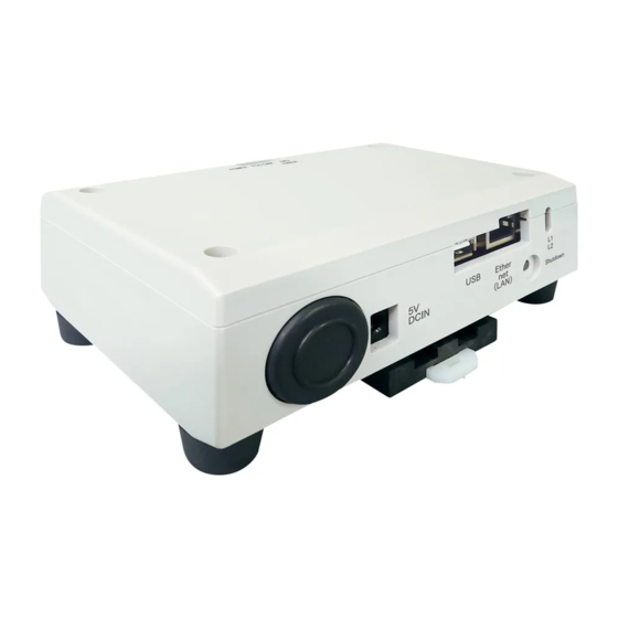
- Page 6 Smart device control interface Installation Manual Component Names POWER TCC-LINK CPU ERROR Ethernet(LAN) Shutdown button 5V DCIN Name Function 5V DCIN Connect the power adapter (For service) Ethernet (LAN) Connect to the Building Management System Shutdown button Shutdown Power indicator Boot status indicator...
-
Page 7: Installation
Smart device control interface Installation Manual Installation REQUIREMENT Do not install the unit in any of the following places. • Humid or wet place • Dusty place • Place exposed to direct sunlight • Place where there is a TV set or radio within one meter •... - Page 8 Smart device control interface Installation Manual Installation Space and Maintenance Space A side space for connecting through cable inlets and an upper space for maintenance must be reserved before installation. The other sides can be adjacent to surrounding objects. 100 mm 100 mm...
-
Page 9: Power And Signal Line Connections
Smart device control interface Installation Manual Power and signal line connections Cables Use the following cable for signal line connections. (Procured locally) Line Description Type 2-core shielded wires For TCC-LINK Wire size 1.25 mm , 1000 m max. total length including air conditioner wiring length Length 2.00 mm... -
Page 10: Installation Manual
Smart device control interface Installation Manual Example of System Wiring Connections Smart device control interface POWER TCC-LINK ERROR TCC-LINK 5V DCIN Ethernet(LAN) wireless router You do not need to connect to a modem if you are not doing modem operations over the internet. -
Page 11: Settings
Smart device control interface Installation Manual Settings 3-1. Switch setting SW300 Not used SW301 Test switch Set all bits to "OFF". SW302 Test button Not used during normal operation. SW100 TCC-LINK terminator resistor setting switch Set the TCC-LINK terminator resistor on the air conditioner side. Set SW100 to "OFF". SW700 Shutdown function button Use this button to stop network process of the Smart device control interface. -
Page 12: Led
Smart device control interface Installation Manual 3-2. LED LED color POWER Power indicator TCC-LINK Orange TCC-LINK communication status indicator ERROR TCC-LINK communication error indicator Green Communication status indicator in the Smart device control interface Green Power indicator Boot status indicator POWER TCC-LINK ERROR... -
Page 13: Factory Default Setting
Smart device control interface Installation Manual 3-6. Factory default setting The default IP address of Smart device control interface is as follow. Default IP address: 192.168.0.99 Subnet mask: 255.255.255.0 * Assign the IP address for the wireless router and the IP address for the Smart device control interface to the same segment. Or, set the Smart device control interface to automatically acquire an IP address. - Page 14 Smart device control interface Installation Manual Confirm communications over the internet * Implement this only if you are operating the product over the internet. If you are not doing operations over the internet, then the test run were finished in the previous section. If you are operating over the internet, you need to disconnect the Smart device control interface from the wireless router to which it is connected, and then connect it to a different internet environment through which it can communicate (4G/LTE communications etc.).
- Page 15 DEA6729101...