Advertisement
Table of Contents
eSpace U1910&U1911&U1930&U1960&U1981
V200R003
Quick Installation Guide
Issue: 01
Date: 2015-02-01
Product Overview
The eSpace U1900 series are switches used in Huawei IP Telephony (IPT)
solutions and provide VoIP solutions that meet requirements of different
enterprises. This document describes how to quickly complete hardware
installation for the U1910&U1911&U1930&U1960&U1981.
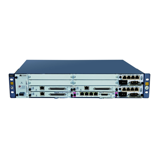
Device Appearance
Board Appearance
Boards for Device Models
U1910&U1930
Note: Boards marked with
control boards. Slots marked with
slots for installing main control boards.
CVP*
ASI
OSU
MTU
U1911&U1960
&U1981
BTU
SCU*
*
are main
*
8
Slot Distribution
Fan box
Fan box
Fan box
Fan box
are
Copyright © Huawei Technologies Co., Ltd. 2015.
1
All rights reserved.
Fan box
Board
Power supply
Grounding hole
Mount angle
Device model label
Board model label
Ejector lever
Screw
Indicator
--
--
--
--
0
2
1
3*
0
2
1
3*
U1930&U1960
0
4
1
5
2
6
3
7*
4
0
1
5
2
6
3*
7*
U1910
Power
supply 1
Power
supply 2
U1911
Power
supply
Power
supply 1
Power
supply 2
U1981
Power
supply 1
Power
supply 2
Advertisement
Table of Contents

Related Manuals for Huawei eSpace U1900 Series


Summary of Contents for Huawei eSpace U1900 Series
-
Page 1: Product Overview
Issue: 01 Date: 2015-02-01 Product Overview The eSpace U1900 series are switches used in Huawei IP Telephony (IPT) solutions and provide VoIP solutions that meet requirements of different enterprises. This document describes how to quickly complete hardware installation for the U1910&U1911&U1930&U1960&U1981. -
Page 2: Installation Procedure
Precautions ! DANGER Do not install or remove a power cable with power on. Transient contact between the core of the power cable and the conductor might generate electric arc or spark, which can cause fire or damage to the human body. Before installing or removing the power cable, turn off the power. -
Page 3: Unpacking Inspection
1 Preparation Unpacking Inspection Check the received materials according to the packing list and ensure that all the materials specified in the contract arrive at the site. After the inspection, sign on the packing list with the customer and keep a backup of the packing list. Packing List (Major Device) xxxxx xxxxx... -
Page 4: Installing A Board
3 Installing a Board Installing a Board Loosen the screws on the filler panel and use the flat-head screwdriver to remove the filler panel. Insert the board into the empty slot, press the ejector lever into place, and fasten the captive screws. Adjusting Components on the Board If you want to use the T1 trunk, you must remove the jumper caps on the CVP board (U1910&U1930) or MTU board (U1911&U1960&U1981). -
Page 5: Connecting Cables
4 Connecting Cables Hardware Device Networking PSTN or traditional Distribution frame Operation terminal Ethernet switch Power socket U1900 Distribution frame Ground bar PSTN IP Phone POTS POTS Ethernet cable High-density user cable PGND cable E1/T1 trunk cable Power cable... -
Page 6: Connecting The Network Cables
Connecting the PGND Cables Use the PGND cables to connect the device to the ground bar or ground point of the grounded cabinet. A PGND cable must be as short as possible and generally cannot exceed 45 cm. ! CAUTION Ensure that the device is effectively connected to the nearest ground to avoid noises in voice calls. -
Page 7: Connecting The Power Cables
Connecting the High-Density User Cables Connect and fasten one end of the high-density user cable to the FXS/FXO port on the ASI or OSU board, and connect the other end to a POTS phone or an FXS port of the upper-level office directly or through the distribution frame. The high-density user cable delivered with the device has no RJ11 connector assembled. -
Page 8: Follow-Up Procedure
Follow-up Procedure Visit http://support.huawei.com/enterprise, download the eSpace U1900 Unified Gateway Product Documentation or eSpace UC IPT Quick Configuration Guide, log in to the device, and begin to configure it according to the guide. You can also use a mobile device to scan the following QR code to download and read related electronic documents. - Page 9 Appendixes Assembling the Signal Cable Connectors Assembling the SMB/BNC Connector (for 75-ohm E1 Cables) The SMB and BNC connectors are used by 75-ohm un-balanced E1 trunk cables. Depending on the device model, either of the following E1 trunk cables with a BNC male connector assembled is delivered with the device.
- Page 10 Pos.1 4E1 trunk cable pin assignment 1E1 trunk cable pin assignment DB26 Pin Foot Signal Port DB26 Pin Foot Signal Port DB26 RX0+/RX0- RX+/RX- 19/20 TX0+/TX0- TX+/TX- RX1+/RX1- 2E1 trunk cable pin assignment Pos.26 21/22 TX1+/TX1- DB26 Pin Foot Signal Port RX2+/RX2- Pos.1...
- Page 11 Assembling the RJ48C Connector (for 120-ohm E1 Cables) The 75-to-120 ohm E1 trunk balun box can convert 75-ohm unbalanced single-ended signals of the device to 120-ohm balanced differential signals so that the device can connect to a variety of peer devices through E1 trunks. If the peer connector is not RJ48C, you can reassemble a RJ48C connector by referring to the pin assignment.
- Page 12 Assembling the RJ45 Connector (for Network Cables) The device has adaptive network ports and can connect to the switch using straight- through or crossover cables. The BTU board of the U1911&U1960&U1981 can also connect to the peer NT device using straight-through network cables. If you need to prepare a straight-through or crossover cable, strip off the jacket of the twisted-pair cable, insert the core wires into the eight-pin feet of a RJ45 connector according to the pin assignment described in the following table, and use a crimping tool to crimp the...