
Related Manuals for Siemens FC1008-A


Summary of Contents for Siemens FC1008-A
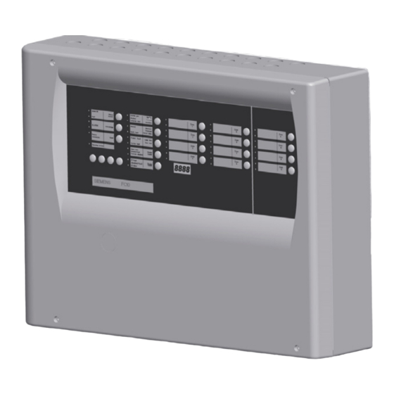
- Page 1 FC1008/12-A/ -B/ -C Fire control unit Technical specification Building Technologies Fire Safety & Security Products...
- Page 2 Data and design subject to change without notice. / Supply subject to availability. © Siemens Switzerland Ltd 2004-2010 We reserve all rights in this document and in the subject thereof. By acceptance of the document the recipient acknowledges these rights and undertakes not to publish the document nor the subject thereof in full or in part, nor to make them available to any third party without our prior express written authorization, nor to use it for any purpose other than for which it was delivered to him.
-
Page 3: Table Of Contents
About this document ................5 Safety regulations ...................7 Signal words and symbols ................7 2.1.1 Classification and meaning of signal words..........7 2.1.2 Symbols and their meaning ..............7 2.1.3 Classification and meaning of additional symbols ........7 Safety-relevant working instructions ............8 System description .................9 General .....................9 Main features ....................9 Specified standards and options.............10... - Page 4 Configuration..................30 Programming user functions ..............30 Programming steps .................32 Programmable functions .................34 8.3.1 Step 1, timer V1 ..................34 8.3.2 Step 2, timer V2 ..................34 8.3.3 Step 3, zone processing on alarm ............35 8.3.4 Step 4, LED activation mode..............35 8.3.5 Step 5, activation mode of control lines ..........35 8.3.6 Step 6, measures against false alarms...........36 8.3.7...
-
Page 5: About This Document
Disregard of the safety regulations The products are designed for an appropriate use and were tested for faultless functioning. Siemens disclaims all liability for damage or personal injuries caused by the incorrect application of the instructions or disregard of warnings of danger contained in the documentation. - Page 6 Product data sheet FC1008/12 008331 FD20 detector system List of compatibility Download The most recently released technical documentation for customers can be found in the Siemens Intranet. Standard symbols Result, note Text in italic Quotation, exact match Cross reference ...
-
Page 7: Safety Regulations
Safety regulations Safety regulations This chapter describes the danger levels and the relevant safety regulations appli- cable for the use of our products. Please read the work instructions as well as the chapter About this document thoroughly before beginning any work. Signal words and symbols 2.1.1 Classification and meaning of signal words... -
Page 8: Safety-Relevant Working Instructions
Safety regulations Safety-relevant working instructions Country-specific standards The products are developed and produced in compliance with the relevant interna- tional and European safety standards. Should additional country-specific, local safety standards or regulations concerning project planning, mounting, installation, operation and disposal of the product apply in the place of operation, then these standards or regulations must also be taken into account in addition to the safety regulations mentioned in the product documentation. -
Page 9: System Description
The FC10 has all the functions that are necessary to build up small and me- dium size fire detection systems in a very efficient way. Control unit variants 8 zones: 12 zones: FC1008-A «STANDARD» FC1012-A «STANDARD» FC1008-B «GB»... -
Page 10: Specified Standards And Options
System description Specified standards and options EN54-2 Fulfilled Basic functions Options and associated requirements Related FC10 configuration / Fulfilled connection Sounder line 1 Output to fire alarm device EN54-1 / C Step 5 option 1 ( Fire alarm devices ) Step 4 option 7 Sounder line 3 7.9.1... -
Page 11: Technical Data
System description Technical data Collective lines (zones) 8 or 12 Number of detectors per line max. 32 Compatible detector series Detector line type “Cerberus” Cerberus (DS1100, MS24, MS9, MS7, MS6) – Sinteso (FDOOT249-1) 4) – Detector line type Standard Standard (Synova Series 300C) –... -
Page 12: Installation
Installation Installation Assembly Components Mains connection and circuit breaker (fuse), factory mounted. 230 VAC main connection from below (recomended) Power supply (70 W) Mainboard Nock-outs for cable entries 20 mm; top 17, bottom 3 Display module (option) Line extension card, FC1012 only Control line extension card (optional) under Line extension card Key switch Nordic (variant Nordic only) Key switch set (option) -
Page 13: Mounting
Installation Mounting Procedure 1. Remove front cover 2. Determine mounting location (not behind a door) 3. Mark position of mounting screws (use enclosed drilling template) and drill holes. Installation accessories not included in cabinet: screws min. 4 x 50 mm –... -
Page 14: Function And Design
Function and design Function and design Mainboard hardware settings CN14 PU18 PU11 PU10 CN26 PU20 CN11 PU26 PU16 CL23 CL24 PU19 CN10 PU17 PU25 Function Parameter Remark PU1 … Detector line 1 to 8 ON = none current limited (Cerberus) factory-set = ON OFF = current limited (Synova) not used... -
Page 15: Mainboard
Function and design Peripheral connections 5.1.1 Mainboard Z-diode 5,6V 1N4007 DRIVER ALARM FAULT ALARM LIN1 LIN2 LIN3 LIN4 LIN5 LIN6 LIN7 LIN8 FAULT RT ALARM RT LIN1 LIN2 LIN3 LIN4 LIN5 LIN6 LIN7 LIN8 CL22 Do not connect driver outputs directly to plus potential! Outputs may be damaged. -
Page 16: Power Supply
Function and design Driver outputs Function / Application Load / rating Remarks Mode manned active if system is in mode manned max. 40 mA/24 V for internal and external use – Alarm 1 active on Alarm 0 and 1 (inactive on Alarm 2) blocked with controls disabled Alarm 2 active on Alarm 2 until Reset... -
Page 17: Manual Call Point Detection
Function and design 5.1.4 Manual call point detection It is possible to differentiate whether a detector or a manual call point has initiated alarm on the detector line. In this case manual call points must be equipped with a z-diode 5.6V/1W. Detectors Manual call point Detectors... -
Page 18: Control Line Extension Card
Function and design 5.1.6 Control line extension card Summery The optional control line extension card features 4 monitored control outputs (con- trol line 3 - 6). The following devices can be connected to the control outputs: Alarm devices like horns or flashlights –... -
Page 19: Connection To Fault Information According En54-2 Output J En54-1
Function and design 5.1.7 Connection to fault information according EN54-2 output J EN54-1 680 Ω 10 kΩ 12 V 100 mA/T (– –) Extra relays 12 VDC, order to be done locally assembly place see page 12 pos. 14 Extra fuse in a safety housing, order to be done locally 100 mA/T Building Technologies A6V10265083_a_en_-- Fire Safety &... -
Page 20: Event Processing
Function and design Event processing 5.2.1 Alarm The processing of alarm events is programmable mainly to prevent the unneces- sary turnout of fire department for minor incidents. It involves personnel in the alarming sequence and relies on the operating mode manned. The system has to be run in operating mode manned as long as the responsible personnel is present. -
Page 21: Operation And Indicator Elements, Mode Of Operation (Pmi)
Operation and indicator elements, mode of operation (PMI) Operation and indicator elements, mode of opera- tion (PMI) Operating panel 6.1.1 General The system operating panel is also called Person Machine Interface - PMI. Overview operating functions Related to Alarm Related to disable system parts Related to system test Acknowledge Disable / Enable zones 1 to xx... -
Page 22: Indicators
Operation and indicator elements, mode of operation (PMI) 6.1.2 Indicators Labeling State active System ON if system is in operation (micro computer working) Fault fast if any system part is on Fault buzzer with pulsating sound – 3 and 4 ALARM if system is on Alarm either... -
Page 23: Operating Keys
Operation and indicator elements, mode of operation (PMI) 6.1.3 Operating keys Keys Keys 9 9 9 9 Labelling Access Function Silence buzzer Level 2 to de-activate the buzzer Acknowledge to acknowledge Alarms and Faults – Level 2 to stop horn test before running time (30 sec.) is –... -
Page 24: Zone Indicators And Keys
Operation and indicator elements, mode of operation (PMI) 6.1.4 Zone indicators and keys Zone LED red Zone LED yellow Possible operating states zone LED zone red LED zone yellow Alarm unacknowledged fast 1st Alarm acknowledged slow Sub sequent alarm acknowledged (Alarm active) Fault line break or line short 2) fast Zone disabled... -
Page 25: Display Module
Operation and indicator elements, mode of operation (PMI) Display module 6.2.1 General Optional display module that can be added on request in order to provide the func- tions listed below. Functions and displayed information Alarm counter Counts up to 9999 alarms spontaneous display –... -
Page 26: Set Clock
Operation and indicator elements, mode of operation (PMI) 6.2.3 Set clock Set date and time 1. Give operating access on level 2 the system may not display any alarm or fault – 2. Hold key reset, key in 4233, release key reset and confirm by pressing key ac- knowledge LED manned and operating access flash alternately and display shows –... -
Page 27: Poll Service Informations
Operation and indicator elements, mode of operation (PMI) 6.2.4 Poll service informations The following information can be displayed on the display module: last change of configuration (date/time and check sum) last test alarm (date/time and zone number) version of firmware ... -
Page 28: Commissioning
Commissioning Commissioning Procedure Work to be done before commissioning installation of detector lines must be completed the connection of all detector bases and manual call points must be tested control unit must be mounted inscription stripes must be labeled and inserted ... -
Page 29: Testing Peripheral Devices
Commissioning Testing peripheral devices Procedure Testing smoke detectors with DZ1193 or RE6 1. Set zone to mode detector test 2. Place testing unit on detector head 3. Wait until LED at detector head is on 4. Remove testing unit - automatic Reset of test alarm after 10 sec. 5. -
Page 30: Configuration
Configuration Configuration Programming user functions In order to fulfill the local requirements, the programmable user functions may be adjusted by the single programming steps. 9 9 9 9 9 9 9 9 Procedure to enter programming mode / Access Level 3 1. - Page 31 Configuration Set user functions to factory default settings The user functions of all programming steps can be set to factory default values with one operation. 1. Disconnect mains and battery 2. Press and hold numeric keys (7) 1, 2, 3, 4 simultaneously followed by reconnect- ing mains LED block (1) starts flashing –...
-
Page 32: Programming Steps
Configuration Programming steps 9 9 9 9 9 9 9 9 The selected programming steps are either indicated by the LED block (4), or for programming steps 1 to 8 the corresponding LED is lit, – for programming steps 9 to 16 the corresponding LED is flashing –... - Page 33 Configuration Basic programming steps STEP Define function Timer V1 Timer V2 Processing of zone Alarm (zone type) LED activation mode LED Remote transmission LED Alarm LED System part disabled on mode manned No Resound or not on new alarm ...
-
Page 34: Programmable Functions
Configuration Programmable functions 9 9 9 9 9 9 9 9 Procedure 1. Select the desired step with key (2) or (3) 2. Press the zone keys (6) as many times until the desired option is indicated with the corresponding zone LED (5) according to the following tables. 8.3.1 Step 1, timer V1 Option... -
Page 35: Step 3, Zone Processing On Alarm
Configuration 8.3.3 Step 3, zone processing on alarm Option Setting LED zone 1 - x yellow Function: Zone alarm processing (zone type) via timer V1/V2 Zone 1 - x Default off direct (timer bypassed) 1) Alarm 0 (internal) 1) - RT and timer V1/V2 not initiated - Horn activated (unless disengaged in step 7) via timer V1/V2, but call points always initiate Alarm 2 (direct) -
Page 36: Step 6, Measures Against False Alarms
Configuration 8.3.6 Step 6, measures against false alarms Option Setting LED zone 1 - x yellow Function: Zone with alarm verification no alarm verification zone 1 – x Default off Alarm only if second Alarm within 60 sec. 1st alarm = automatic Reset with short flash up of zone Function: Zone disabled in mode manned not disabled zone 1 –... -
Page 37: Step 11, Cross Zoning
Configuration 8.3.11 Step 11, cross zoning Option Setting LED zone 1 - x yellow Function: Zone pair in cross-zoning on alarm no cross-zoning zone A+B Default off cross-zoning type 1 zone A or B = no Alarm * – zone A + B = Alarm 1 –... -
Page 38: Step 14 Not Used
Configuration 8.3.14 Step 14 not used 8.3.15 Step 15, special parameters Option Setting LED zone 1 LED zone 2 yellow red yellow Function: Acknowledge and Reset from external blocked during RT alarm active not blocked zone 1 Default off blocked Function: Zones set to option 2 in step 10 with special disabling procedure not activated zone 1... -
Page 39: Step 24, Display Switching Time
Configuration 8.3.19 Step 24, display switching time Option Setting LED zone 1 LED zone 2 yellow yellow Function: Display of switching time after manual switch from manned to unmanned switching time displayed zone 1 Default off switching time not displayed 8.3.20 Step 25, switching mode summer/winter time Option Setting... -
Page 40: Log Sheet For Programmed User Functions
Configuration Log sheet for programmed user functions Installation: …………………………………………………………………………………………………… Selected pre-setting: ………… Basic programming steps Programming steps and functions Individual settings of a selected pre-setting Factory default setting Timer V1 min : ………………… Timer V2 min : ………………… Processing of zone Alarm (zone type) Option 1, zone: ……………. -
Page 41: Checksum
Configuration Display programming steps Programming steps and functions Set options (parameter) Individual settings of a Selectable pre-settings selected pre-setting Factory indicating mode display Function display mode ……………… Function alarm counter ……………… switching mode manned/unmanned ……………… display switching time ………………... -
Page 42: Maintenance
Maintenance Maintenance General The fire detection installation requires only little maintenance work. It has a high degree of self monitoring, such as detectors monitored on presence, lines on wire break and short circuit call points monitored on broken glass, lines on wire break and short circuit ... - Page 43 Maintenance Operating panel Performance checks Interval in years Clean front panel with mild soap - do not use aggressive or abrasive solvents Activate lamp test Check correctness and readability of the inscription stripes Check key-click of each key Check access facility Inside control unit Performance checks Interval in years...
-
Page 44: Trouble Shooting
Trouble shooting Trouble shooting 10.1 Interpretation of fault LED flashing 9 9 9 9 17 (23) Indicator Cause / Action to be taken LED 2 Fault There is a fault in the system flashing fast check if there is another fault LED flashing, if not ... -
Page 45: Components And Spare Parts
Components and spare parts Components and spare parts 11.1 Components Type Part number Description Remarks FC1008-A S54380-C4-A1 control unit 8 zones FC1008-B S54380-C4-A10 control unit 8 zones GB FC1008-C S54380-C4-A20 control unit 8 zones Nordic FC1012-A S54380-C5-A1 control unit 12 zones... -
Page 46: Disposal And Environmental Protection
12.1 General The customer is in charge of the disposal of Siemens fire detection systems. In case of any uncertainty relative to the disposal process, which might cause danger to people or to the environment, please consult the Technical Customer Service of Siemens Building Technologies AG. - Page 47 Disposal and environmental protection Building Technologies A6V10265083_a_en_-- Fire Safety & Security Products 03.2010...
- Page 48 Siemens Switzerland Ltd © Siemens Switzerland Ltd 2004-2010 Industry Sector Data and design subject to change without notice. Building Technologies Division International Headquarters Gubelstrasse 22 6301 Zug, Switzerland Tel. +41 41 - 724 24 24 www.siemens.com/buildingtechnologies Document no. A6V10265083_a_en_-- Manual - Edition 03.2010...