
Related Manuals for ABB EL3000 Series


Summary of Contents for ABB EL3000 Series
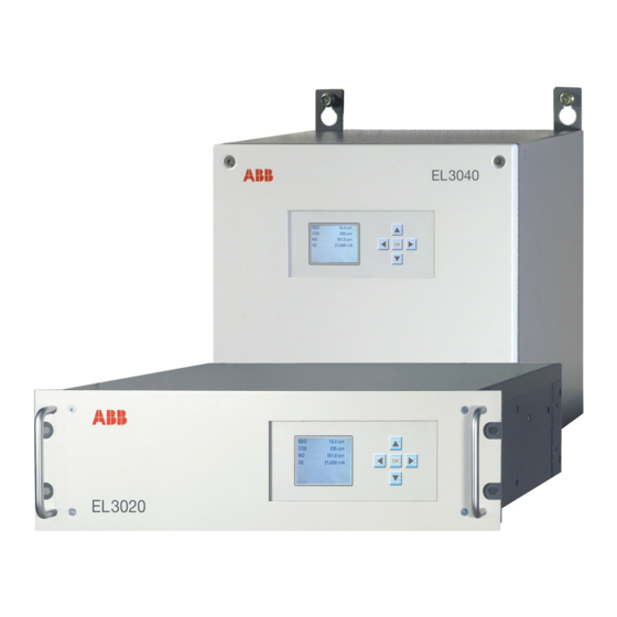
- Page 1 — ABB MEASUREMENT & ANALYTICS | COMMISSIONING INSTRUCTION EL3000 Continuous gas analyzers So smart, they’re simple Measurement made easy...
-
Page 3: Table Of Contents
EL3000 CONTINUOUS GAS ANALYZERS CI/EL3000-EN REV. B Contents Preface ..................................5 Guideline for installation and commissioning ....................6 Safety information ..............................7 Intended application ....................7 Safety information ...................... 7 Fidas24: Information on the safe operation of the gas analyzer ....... 9 ... - Page 4 EL3000 CONTINUOUS GAS ANALYZERS CI/EL3000-EN REV. B Gas connections for Magnos28 (Model EL3040) ..........72 Gas connections for Magnos27 (Model EL3020) ..........73 Gas connections for Magnos27 with Uras26 (Model EL3020) ......74 Gas connections for ZO23 (Model EL3020) ............75 ...
-
Page 5: Preface
Technical information Certificates Internet You will find information on ABB Analytical products and services on the Internet at "http://www.abb.com/analytical". Service contact If the information in this operating instruction does not cover a particular situation, ABB Service will be pleased to supply additional information as required. -
Page 6: Guideline For Installation And Commissioning
EL3000 CONTINUOUS GAS ANALYZERS CI/EL3000-EN REV. B Guideline for installation and commissioning Basic steps The following basic steps should be followed for the installation and com- missioning of the gas analyzer: Note the information on the intended application (see page 7). Follow safety precautions (see page 7). -
Page 7: Safety Information
EL3000 CONTINUOUS GAS ANALYZERS CI/EL3000-EN REV. B Safety information Intended application Intended application of the gas analyzer The gas analyzer is designed for continuous measurement of the concentra- tion of individual components in gases or vapors. Any other use is not as specified. The specified use also includes taking note of this operating instruction. - Page 8 EL3000 CONTINUOUS GAS ANALYZERS CI/EL3000-EN REV. B Special information and precautions These include The content of this operating instruction, The safety information affixed to the device, The applicable safety precautions for installing and operating electrical devices, Safety precautions for working with gases, acids, condensates, etc.
-
Page 9: Fidas24: Information On The Safe Operation Of The Gas Analyzer
EL3000 CONTINUOUS GAS ANALYZERS CI/EL3000-EN REV. B Fidas24: Information on the safe operation of the gas analyzer CAUTION The gas analyzer uses hydrogen as a combustion gas! All the information and instructions contained in this operating instruc- tion must be complied with without fail to ensure safe operation of the gas analyzer! Measures of the manufacturer The following measures ensure that the enrichment of combustion gas or an... - Page 10 EL3000 CONTINUOUS GAS ANALYZERS CI/EL3000-EN REV. B The combustion gas flow rate must be limited to a maximum of 10 l/h of H or 25 l/h of H /He mixture. For this purpose, the end user has to provide suitable measures (see page 34) outside the gas analyzer. ...
-
Page 11: Version With Type Of Protection Ii 3G For Measurement Of Non-Flammable Gases And Vapors
EL3000 CONTINUOUS GAS ANALYZERS CI/EL3000-EN REV. B Version with type of protection II 3G for measurement of non-flammable gases and vapors NOTE The version for the measurement of flammable gases and vapors and the explosion-proof version with degree of protection II 3G (see page 11) are different versions of the gas analyzer and designed for different applica- tions. - Page 12 EL3000 CONTINUOUS GAS ANALYZERS CI/EL3000-EN REV. B Special requirements The cables have to be properly inserted in the screwed cable glands and sealed by screwing the nut firmly in order to comply with degree of case protection IP65. Cable connectors not in use have to be closed with suitable vent plugs in order to ensure degree of case protection IP65 here as well.
-
Page 13: Preparation For Installation
EL3000 CONTINUOUS GAS ANALYZERS CI/EL3000-EN REV. B Preparation for installation Scope of supply and delivery Scope of supply and delivery Gas analyzer model EL3020 (19-inch housing) or model EL3040 (wall-mount housing) Screwed fittings with tubing connectors for the connection of flexible tubes ... -
Page 14: Material Required For The Installation (Not Supplied)
EL3000 CONTINUOUS GAS ANALYZERS CI/EL3000-EN REV. B Material required for the installation (not supplied) Gas connections For the connection of pipelines: Threaded connections with a ⅛ NPT thread and PTFE sealing tape Fidas24: Use only metal threaded connectors! Fidas24: Gas lines Process gases, test gases and waste air ... - Page 15 EL3000 CONTINUOUS GAS ANALYZERS CI/EL3000-EN REV. B Signal lines Select conductive material which is appropriate for the length of the lines and the predictable current load. Notes concerning the cable cross-section for connection of the I/O modules: The max.
-
Page 16: Requirements For The Installation Site, Power Supply
EL3000 CONTINUOUS GAS ANALYZERS CI/EL3000-EN REV. B Requirements for the installation site, power supply NOTE For the analyzers ZO23 and Fidas24 the information contained in the sec- tions "ZO23: Preparation for installation" (see page 28) or "Fidas24: Prepara- tion for installation" (see page 34) must be considered in addition. Requirements for the installation site The gas analyzer is only intended for installation indoors. - Page 17 EL3000 CONTINUOUS GAS ANALYZERS CI/EL3000-EN REV. B Special requirements for the gas analyzer Model EL3020 for the measurement of flammable gases An unimpeded exchange of air with the surroundings must be possible around the gas analyzer from beneath (base plate) and from behind (gas connections).
- Page 18 EL3000 CONTINUOUS GAS ANALYZERS CI/EL3000-EN REV. B Safety Test to EN 61010-1:2010 Class of protection Overvoltage category/ Power supply: II/2 degree of pollution Signal inputs and outputs: II/2 Safe isolation Galvanic isolation of the power supply from the other circuits by means of reinforced or double in- sulation.
-
Page 19: Uras26: Preparation For Installation
EL3000 CONTINUOUS GAS ANALYZERS CI/EL3000-EN REV. B Uras26: Preparation for installation Sample gas Sample gas inlet conditions The analyzer must not be used for measurement of ignitable gas/air or gas/oxygen mixtures. Temperature The dew point of the sample gas must be at least 5 °C lower than the lowest ambient temperature in the overall sample gas path. - Page 20 EL3000 CONTINUOUS GAS ANALYZERS CI/EL3000-EN REV. B Analyzer(s) Test gas for zero-point calibration Test gas for end-point calibration and single-point calibration Uras26 + Magnos27 IR sample component-free test gas Calibration cells or span gas* (automatic calibration) with O concentration in an existing measuring range or ambient air.
-
Page 21: Limas23: Preparation For Installation
EL3000 CONTINUOUS GAS ANALYZERS CI/EL3000-EN REV. B Limas23: Preparation for installation Sample gas Sample gas inlet conditions The analyzer must not be used for measurement of flammable gases and ignitable gas/air or gas/oxygen mixtures. Temperature The dew point of the sample gas must be at least 5 °C lower than the lowest ambient temperature in the overall sample gas path. - Page 22 EL3000 CONTINUOUS GAS ANALYZERS CI/EL3000-EN REV. B Dew point The dew point of the test gases must be approximately the same as the dew point of the sample gas. NOTE The notes for calibrating must be considered. Pressure sensor The pressure sensor is installed in the gas analyzer ex works. It is located downstream the sample cell.
-
Page 23: Magnos206: Preparation For Installation
EL3000 CONTINUOUS GAS ANALYZERS CI/EL3000-EN REV. B Magnos206: Preparation for installation Sample gas Sample gas inlet conditions The analyzer must not be used for measurement of ignitable gas/air or gas/oxygen mixtures. Temperature The sample gas dew point must be at least 5 °C lower than the lowest ambient temperature in the overall sample gas path. - Page 24 EL3000 CONTINUOUS GAS ANALYZERS CI/EL3000-EN REV. B Test gases Analyzer Test gas for zero-point calibration Test gas for end-point calibration and single-point calibration Magnos206 Oxygen-free process gas Process gas with known O concen- tration Magnos206 with Test gas with O concentration near Test gas with O concentration near...
-
Page 25: Magnos28: Preparation For Installation
Changes in the sample gas flow rate should be avoided when using highly suppressed measurement ranges. Corrosive gases Consultation with ABB Analytical is required if the sample gas contains Cl HCl, HF or other corrosive components. FFKM75 seals must be used if the sample gas contains NH . - Page 26 EL3000 CONTINUOUS GAS ANALYZERS CI/EL3000-EN REV. B Test gases Analyzer Test gas for zero-point calibration Test gas for end-point calibration and single-point calibration Magnos28 Oxygen-free process gas Process gas with known O concen- tration Magnos28 with suppressed Test gas with O concentration near Test gas with O concentration near...
-
Page 27: Magnos27: Preparation For Installation
EL3000 CONTINUOUS GAS ANALYZERS CI/EL3000-EN REV. B Magnos27: Preparation for installation Sample gas Sample gas inlet conditions The analyzer must not be used for measurement of flammable gases and ignitable gas/air or gas/oxygen mixtures. Temperature The dew point of the sample gas must be at least 5 °C lower than the lowest ambient temperature in the overall sample gas path. -
Page 28: Zo23: Preparation For Installation
EL3000 CONTINUOUS GAS ANALYZERS CI/EL3000-EN REV. B ZO23: Preparation for installation Sample gas CAUTION The gas analyzer may not be used for the measurement of ignitable gas/air or gas/oxygen mixtures. Sample gas inlet conditions Temperature +5 to +50 °C Inlet pressure ≤... - Page 29 EL3000 CONTINUOUS GAS ANALYZERS CI/EL3000-EN REV. B Test gases Reference point (= electrical zero) Clean ambient air; its oxygen concentration can be calculated from the value for dry air and the factor for the consideration of the water vapor content. Example: Water vapor content at 25 °C and 50 % relative humidity = 1.56 Vol.-% of H ...
- Page 30 EL3000 CONTINUOUS GAS ANALYZERS CI/EL3000-EN REV. B Example of sample conditioning Sampling point with primary shut-off valve Multi-way ball valve 3/2-way ball valve Fine-control valve Flowmeter with needle valve and alarm contact 2-way ball valve 2-way ball valve Air filter Gas analyzer Flowmeter without needle valve, with alarm contact Purge gas cylinder with N...
- Page 31 EL3000 CONTINUOUS GAS ANALYZERS CI/EL3000-EN REV. B Gas sampling The nominal diameter of the line from the sampling point to the first switch-over valve should be 4 mm. A bypass can be positioned upstream of the first switch-over valve, in order to obtain a faster analysis.
-
Page 32: Caldos27: Preparation For Installation
EL3000 CONTINUOUS GAS ANALYZERS CI/EL3000-EN REV. B Caldos27: Preparation for installation Sample gas Sample gas inlet conditions The analyzer must not be used for measurement of ignitable gas/air or gas/oxygen mixtures. Temperature The dew point of the sample gas must be at least 5 °C lower than the lowest ambient temperature in the overall sample gas path. - Page 33 EL3000 CONTINUOUS GAS ANALYZERS CI/EL3000-EN REV. B Pressure sensor The pressure sensor is installed in the gas analyzer ex works. It is connected to a connection port via an FPM tube. Gas connections see sections "Gas connections Caldos27 (Model EL3020)" (see page 77) and "Gas connections Caldos27 (Model EL3040)"...
-
Page 34: Fidas24: Preparation For Installation
EL3000 CONTINUOUS GAS ANALYZERS CI/EL3000-EN REV. B Fidas24: Preparation for installation Sample gas Sample components Hydrocarbons (THC). The sample component concentration in the sample gas path should not exceed the temperature-dependent LEL. The analyzer temperature is 180 °C. Sample gas inlet conditions Temperature ≤... - Page 35 /He mixture. Suitable measures outside the gas analyzer must be provided by the end user for this purpose. ABB recommends the use of a bulkhead fitting with an integrated flow re- strictor which must be installed in the combustion gas supply line. This bulkhead fitting can be purchased from ABB: ...
- Page 36 EL3000 CONTINUOUS GAS ANALYZERS CI/EL3000-EN REV. B Test gases Zero-point calibration Quality Nitrogen, Quality 5.0, synthetic air or catalytically cleaned air with an organic C content < 1 % of span Inlet pressure = 1000 ± 100 hPa Flow 130 to 250 l/h End-point calibration Quality Sample component or substitute gas component in ni-...
-
Page 37: Sample Gas Inlet And Outlet Conditions
EL3000 CONTINUOUS GAS ANALYZERS CI/EL3000-EN REV. B Sample gas inlet and outlet conditions Analyzers Uras26 see section "Uras26: Preparation for installation" (see page 19) Limas23 see section "Limas23: Preparation for installation" (see page 21) Magnos206 see section "Magnos206: Preparation for installation" (see page 23) Magnos28 see section "Magnos28: Preparation for installation"... -
Page 38: Pressure Sensor
EL3000 CONTINUOUS GAS ANALYZERS CI/EL3000-EN REV. B Pressure sensor In which gas analyzers is a pressure sensor installed? Gas analyzer Pressure sensor Uras26, Limas23, Caldos27 installed ex works Magnos206, Magnos28, Magnos27 installed ex works as an option Fidas24, ZO23 not required Information for the proper operation of the pressure sensor ... -
Page 39: Housing Purge
EL3000 CONTINUOUS GAS ANALYZERS CI/EL3000-EN REV. B Housing purge Housing design Remark: Housing purge in the Fidas24 is described in a separate section, see below. Housing Purge is only possible with the wall-mount housing (EL3040 model). The purging gas connectors (⅛-NPT female thread) are factory-installed based on orders. - Page 40 EL3000 CONTINUOUS GAS ANALYZERS CI/EL3000-EN REV. B Housing purge during operation when measuring flammable gases The housing has to be purged with nitrogen. Purge gas flow 1 to 20 l/h. The purge gas flow must be monitored at the purging gas outlet. Housing purge in the Fidas24 The housing purge is implemented in the Fidas24 gas analyzer in such a way that a part (approx.
-
Page 41: Dimensional Drawings
EL3000 CONTINUOUS GAS ANALYZERS CI/EL3000-EN REV. B Dimensional drawings 19-inch housing (Model EL3020) Dimensions in mm (in.) 19-inch housing (Model EL3020 with Magnos27) Dimensions in mm (in.) NOTE Only the front view of the housing with its height differing from the standard dimension is depicted in this dimensional drawing. - Page 42 EL3000 CONTINUOUS GAS ANALYZERS CI/EL3000-EN REV. B Wall-mounting housing (Model EL3040) Dimensions in mm (in.)
-
Page 43: Special Requirements For The Measurement Of Flammable Gases
EL3000 CONTINUOUS GAS ANALYZERS CI/EL3000-EN REV. B Special requirements for the measurement of flammable gases NOTE The version for the measurement of flammable gases and vapors and the explosion-proof version with degree of protection II 3G (see page 11) are different versions of the gas analyzer and designed for different applica- tions. -
Page 44: Installing The Gas Analyzer
EL3000 CONTINUOUS GAS ANALYZERS CI/EL3000-EN REV. B Installing the gas analyzer Unpacking the gas analyzer CAUTION Depending on its design, the gas analyzer weighs 7 to 15 kg (19-inch case – Model EL3020) and 13 to 21 kg (wall-mounting case – Model EL3040)! Unpacking and transporting requires two persons! Unpacking the gas analyzer Remove the accessories (see scope of supply and delivery (see page 13)) -
Page 45: Installing The Gas Connections
EL3000 CONTINUOUS GAS ANALYZERS CI/EL3000-EN REV. B Installing the gas connections NOTES We strongly recommend that you install the gas connections before the gas analyzer is installed, since the gas ports are now easily accessible. The fittings must be clean and free of residue! Contaminants can enter the analyzer and damage it or lead to false measurement results! Do not use sealing compound to seal the gas connections! Constituents of the sealing compound can lead to false measurement results! Use PTFE... - Page 46 EL3000 CONTINUOUS GAS ANALYZERS CI/EL3000-EN REV. B Checking the seal integrity of the sample gas feed path The tightness of the sample gas feed path was checked in the factory. How- ever since it may have been affected during transport of the gas analyzer (e.g.
-
Page 47: Gas Connections For Uras26 (Model El3020)
EL3000 CONTINUOUS GAS ANALYZERS CI/EL3000-EN REV. B Gas connections for Uras26 (Model EL3020) Uras26: Gas connections for flexible tubes (internal gas lines executed as flexible tubes) Sample gas inlet Gas feed path 1 without option "Integrated gas feed" Sample gas outlet Gas feed path 1 Sample gas outlet with the option "Integrated gas feed", connected ex works to 1 Sample gas inlet Gas feed path 1 Sample gas inlet... - Page 48 EL3000 CONTINUOUS GAS ANALYZERS CI/EL3000-EN REV. B Uras26: Gas connections for pipelines (internal gas lines executed as stainless steel pipes) Pressure sensor Design: Screwed fitting with hose nozzle (stainless steel 1.4305/SAE 303) for hose with 4 mm inner di- ameter (supplied) Sample gas inlet Sample gas outlet with one sample cell Sample gas outlet with two sample cells in series...
-
Page 49: Gas Connections For Uras26 (Model El3040)
EL3000 CONTINUOUS GAS ANALYZERS CI/EL3000-EN REV. B Gas connections for Uras26 (Model EL3040) Uras26: Gas connections with 1 gas feed path (internal gas lines executed as flexible tubes or stainless steel pipes) not assigned not assigned Sample gas inlet Sample gas outlet with one sample cell Purge gas inlet for case Purge gas outlet for case not assigned... - Page 50 EL3000 CONTINUOUS GAS ANALYZERS CI/EL3000-EN REV. B Uras26: Gas connections with 2 separate gas feed paths (internal gas lines executed as flexible tubes) not assigned not assigned Sample gas inlet gas feed path 1 Sample gas outlet gas feed path 1 Purge gas inlet for case Purge gas outlet for case Sample gas inlet gas feed path 2...
-
Page 51: Gas Connections For Uras26 With Magnos206 (Model El3020)
EL3000 CONTINUOUS GAS ANALYZERS CI/EL3000-EN REV. B Gas connections for Uras26 with Magnos206 (Model EL3020) Uras26: Gas connections for flexible tubes (internal gas lines executed as flexible tubes) Sample gas inlet Gas feed path 1 without option "Integrated gas feed" Sample gas outlet Gas feed path 1 Sample gas outlet with the option "Integrated gas feed", connected ex works to 1 Sample gas inlet Gas feed path 1... - Page 52 EL3000 CONTINUOUS GAS ANALYZERS CI/EL3000-EN REV. B Uras26: Gas connections for pipelines (internal gas lines executed as stainless steel pipes) Pressure sensor Design: Screwed fitting with hose nozzle (stainless steel 1.4305/SAE 303) for hose with 4 mm inner di- ameter (supplied) Sample gas inlet Sample gas outlet with one sample cell Sample gas outlet with two sample cells in series...
-
Page 53: Gas Connections For Uras26 With Magnos206 (Model El3040)
EL3000 CONTINUOUS GAS ANALYZERS CI/EL3000-EN REV. B Gas connections for Uras26 with Magnos206 (Model EL3040) Uras26: Gas connections with 1 gas feed path (internal gas lines executed as flexible tubes or stainless steel pipes) not assigned not assigned Sample gas inlet Sample gas outlet with one sample cell Purge gas inlet for case Purge gas outlet for case... - Page 54 EL3000 CONTINUOUS GAS ANALYZERS CI/EL3000-EN REV. B Uras26: Gas connections with 2 separate gas feed paths (internal gas lines executed as flexible tubes) not assigned not assigned Sample gas inlet gas feed path 1 Sample gas outlet gas feed path 1 Purge gas inlet for case Purge gas outlet for case Sample gas inlet gas feed path 2...
-
Page 55: Gas Connections For Uras26 With Magnos28 (Model El3020)
EL3000 CONTINUOUS GAS ANALYZERS CI/EL3000-EN REV. B Gas connections for Uras26 with Magnos28 (Model EL3020) Uras26: Gas connections for flexible tubes (internal gas lines executed as flexible tubes) Sample gas inlet Gas feed path 1 without option "Integrated gas feed" Sample gas outlet Gas feed path 1 Sample gas outlet with the option "Integrated gas feed", connected ex works to 1 Sample gas inlet Gas feed path 1... - Page 56 EL3000 CONTINUOUS GAS ANALYZERS CI/EL3000-EN REV. B Uras26: Gas connections for pipelines (internal gas lines executed as stainless steel pipes) Pressure sensor Design: Screwed fitting with hose nozzle (stainless steel 1.4305/SAE 303) for hose with 4 mm inner di- ameter (supplied) Sample gas inlet Sample gas outlet with one sample cell Sample gas outlet with two sample cells in series...
-
Page 57: Gas Connections For Uras26 With Magnos28 (Model El3040)
EL3000 CONTINUOUS GAS ANALYZERS CI/EL3000-EN REV. B Gas connections for Uras26 with Magnos28 (Model EL3040) Uras26: Gas connections with 1 gas feed path (internal gas lines executed as flexible tubes or stainless steel pipes) not assigned not assigned Sample gas inlet Sample gas outlet with one sample cell Purge gas inlet for case Purge gas outlet for case... - Page 58 EL3000 CONTINUOUS GAS ANALYZERS CI/EL3000-EN REV. B Uras26: Gas connections with 2 separate gas feed paths (internal gas lines executed as flexible tubes) not assigned not assigned Sample gas inlet gas feed path 1 Sample gas outlet gas feed path 1 Purge gas inlet for case Purge gas outlet for case Sample gas inlet gas feed path 2...
-
Page 59: Gas Connections For Uras26 With Caldos27 (Model El3020)
EL3000 CONTINUOUS GAS ANALYZERS CI/EL3000-EN REV. B Gas connections for Uras26 with Caldos27 (Model EL3020) Uras26: Gas connections for flexible tubes (internal gas lines executed as flexible tubes) Sample gas inlet Gas feed path 1 without option "Integrated gas feed" Sample gas outlet Gas feed path 1 Sample gas outlet with the option "Integrated gas feed", connected ex works to 1 Sample gas inlet Gas feed path 1... - Page 60 EL3000 CONTINUOUS GAS ANALYZERS CI/EL3000-EN REV. B Uras26: Gas connections for pipelines (internal gas lines executed as stainless steel pipes) Pressure sensor Design: Screwed fitting with hose nozzle (stainless steel 1.4305/SAE 303) for hose with 4 mm inner di- ameter (supplied) Sample gas inlet Sample gas outlet with one sample cell Sample gas outlet with two sample cells in series...
-
Page 61: Gas Connections For Uras26 With Caldos27 (Model El3040)
EL3000 CONTINUOUS GAS ANALYZERS CI/EL3000-EN REV. B Gas connections for Uras26 with Caldos27 (Model EL3040) Uras26: Gas connections with 1 gas feed path (internal gas lines executed as flexible tubes or stainless steel pipes) not assigned not assigned Sample gas inlet Sample gas outlet with one sample cell Purge gas inlet for case Purge gas outlet for case... - Page 62 EL3000 CONTINUOUS GAS ANALYZERS CI/EL3000-EN REV. B Uras26: Gas connections with 2 separate gas feed paths (internal gas lines executed as flexible tubes) not assigned not assigned Sample gas inlet gas feed path 1 Sample gas outlet gas feed path 1 Purge gas inlet for case Purge gas outlet for case Sample gas inlet gas feed path 2...
-
Page 63: Gas Connections For Limas23 (Model El3020)
EL3000 CONTINUOUS GAS ANALYZERS CI/EL3000-EN REV. B Gas connections for Limas23 (Model EL3020) Limas23: Gas connections Sample gas inlet Sample gas outlet Design: Screwed fittings with hose nozzles (stainless steel 1.4305/SAE 303) for hoses with 4 mm inner diameter (supplied) Notes: The pressure sensor (standard) and the oxygen sensor (option) are connected internally in the outlet of the sample cell. -
Page 64: Gas Connections For Limas23 (Model El3040)
EL3000 CONTINUOUS GAS ANALYZERS CI/EL3000-EN REV. B Gas connections for Limas23 (Model EL3040) Limas23: Gas connections Sample gas inlet Sample gas outlet Purge gas inlet for case Purge gas outlet for case Design: ⅛ NPT female thread (stainless steel 1.4305/SAE 303) Connection of flexible tubes: Straight screwed fittings (PP) with nozzles for flexible tubes with inside diameter = 4 mm (supplied) Connection of pipelines: Threaded connections (not supplied) -
Page 65: Gas Connections For Limas23 With Magnos206 (Model El3020)
EL3000 CONTINUOUS GAS ANALYZERS CI/EL3000-EN REV. B Gas connections for Limas23 with Magnos206 (Model EL3020) Limas23: Gas connections Sample gas inlet Sample gas outlet Design: Screwed fittings with hose nozzles (stainless steel 1.4305/SAE 303) for hoses with 4 mm inner diameter (supplied) Note: The pressure sensor is connected internally in the outlet of the sample cell. -
Page 66: Gas Connections For Limas23 With Magnos206 (Model El3040)
EL3000 CONTINUOUS GAS ANALYZERS CI/EL3000-EN REV. B Gas connections for Limas23 with Magnos206 (Model EL3040) Limas23: Gas connections Sample gas inlet Sample gas outlet Purge gas inlet for case Purge gas outlet for case Design: ⅛ NPT female thread (stainless steel 1.4305/SAE 303) Connection of flexible tubes: Straight screwed fittings (PP) with nozzles for flexible tubes with inside diameter = 4 mm (supplied) Connection of pipelines: Threaded connections (not supplied) -
Page 67: Gas Connections For Limas23 With Magnos28 (Model El3020)
EL3000 CONTINUOUS GAS ANALYZERS CI/EL3000-EN REV. B Gas connections for Limas23 with Magnos28 (Model EL3020) Limas23: Gas connections Sample gas inlet Sample gas outlet Design: Screwed fittings with hose nozzles (stainless steel 1.4305/SAE 303) for hoses with 4 mm inner diameter (supplied) Note: The pressure sensor is connected internally in the outlet of the sample cell. -
Page 68: Gas Connections For Limas23 With Magnos28 (Model El3040)
EL3000 CONTINUOUS GAS ANALYZERS CI/EL3000-EN REV. B Gas connections for Limas23 with Magnos28 (Model EL3040) Limas23: Gas connections Sample gas inlet Sample gas outlet Purge gas inlet for case Purge gas outlet for case Design: ⅛ NPT female thread (stainless steel 1.4305/SAE 303) Connection of flexible tubes: Straight screwed fittings (PP) with nozzles for flexible tubes with inside diameter = 4 mm (supplied) Connection of pipelines: Threaded connections (not supplied) -
Page 69: Gas Connections For Magnos206 (Model El3020)
EL3000 CONTINUOUS GAS ANALYZERS CI/EL3000-EN REV. B Gas connections for Magnos206 (Model EL3020) Magnos206: Gas connections Sample gas inlet Sample gas outlet Design: ⅛ NPT female thread (stainless steel 1.4305/SAE 303) Connection of flexible tubes: straight screwed fittings (PP) with nozzles for flexible tubes with inside diameter = 4 mm (supplied) Connection of pipelines: Threaded connections (not supplied) Sample gas outlet with the option "Integrated gas feed", connected ex works to 1 Sample gas inlet... -
Page 70: Gas Connections For Magnos206 (Model El3040)
EL3000 CONTINUOUS GAS ANALYZERS CI/EL3000-EN REV. B Gas connections for Magnos206 (Model EL3040) Magnos206: Gas connections Sample gas inlet Sample gas outlet not assigned not assigned Purge gas inlet for case Purge gas outlet for case Pressure sensor Design: ⅛ NPT female thread (stainless steel 1.4305/SAE 303) Connection of flexible tubes: straight screwed fittings (PP) with nozzles for flexible tubes with inside diameter = 4 mm (supplied) Connection of pipelines: Threaded connections (not supplied) -
Page 71: Gas Connections For Magnos28 (Model El3020)
EL3000 CONTINUOUS GAS ANALYZERS CI/EL3000-EN REV. B Gas connections for Magnos28 (Model EL3020) Magnos28: Gas connections Sample gas inlet Sample gas outlet Design: ⅛ NPT female thread (stainless steel 1.4305/SAE 303) Connection of flexible tubes: straight screwed fittings (PP) with nozzles for flexible tubes with inside diameter = 4 mm (supplied) Connection of pipelines: Threaded connections (not supplied) Sample gas outlet with the option "Integrated gas feed", connected ex works to 1 Sample gas inlet... -
Page 72: Gas Connections For Magnos28 (Model El3040)
EL3000 CONTINUOUS GAS ANALYZERS CI/EL3000-EN REV. B Gas connections for Magnos28 (Model EL3040) Magnos28: Gas connections Sample gas inlet Sample gas outlet not assigned not assigned Purge gas inlet for case Purge gas outlet for case Pressure sensor Design: ⅛ NPT female thread (stainless steel 1.4305/SAE 303) Connection of flexible tubes: straight screwed fittings (PP) with nozzles for flexible tubes with inside diameter = 4 mm (supplied) Connection of pipelines: Threaded connections (not supplied) -
Page 73: Gas Connections For Magnos27 (Model El3020)
EL3000 CONTINUOUS GAS ANALYZERS CI/EL3000-EN REV. B Gas connections for Magnos27 (Model EL3020) Magnos27: Gas connections Pressure sensor (option) not used Sample gas inlet Sample gas outlet Purge gas inlet analyzer Purge gas outlet analyzer Design: Screwed fittings with hose nozzles (stainless steel 1.4305/SAE 303) for hoses with 4 mm inner diameter (supplied) -
Page 74: Gas Connections For Magnos27 With Uras26 (Model El3020)
EL3000 CONTINUOUS GAS ANALYZERS CI/EL3000-EN REV. B Gas connections for Magnos27 with Uras26 (Model EL3020) Magnos27: Gas connections Sample gas inlet Sample gas outlet Purge gas inlet analyzer Purge gas outlet analyzer Design: Screwed fittings with hose nozzles (stainless steel 1.4305/SAE 303) for hoses with 4 mm inner diameter (supplied) Uras26: Gas connections Sample gas inlet... -
Page 75: Gas Connections For Zo23 (Model El3020)
EL3000 CONTINUOUS GAS ANALYZERS CI/EL3000-EN REV. B Gas connections for ZO23 (Model EL3020) ZO23: Gas connections The sample chamber is connected to the sample gas inlet connection via a stainless steel tube on the inlet side and to the sample gas outlet connection via an FPM hose on the outlet side. Sample gas inlet (3 mm Swagelok ®... -
Page 76: Gas Connections For Zo23 (Model El3040)
EL3000 CONTINUOUS GAS ANALYZERS CI/EL3000-EN REV. B Gas connections for ZO23 (Model EL3040) ZO23: Gas connections The sample chamber is connected to the sample gas inlet connection via a stainless steel tube on the inlet side and to the sample gas outlet connection via an FPM hose on the outlet side. Sample gas inlet (3 mm Swagelok®) Sample gas outlet Purge gas inlet for housing... -
Page 77: Gas Connections For Caldos27 (Model El3020)
EL3000 CONTINUOUS GAS ANALYZERS CI/EL3000-EN REV. B Gas connections for Caldos27 (Model EL3020) Caldos27: Gas connections Sample gas inlet Sample gas outlet Design: ⅛ NPT female thread (stainless steel 1.4305/SAE 303) Connection of flexible tubes: straight screwed fittings (PP) with nozzles for flexible tubes with inside diameter = 4 mm (supplied) Connection of pipelines: Threaded connections (not supplied) Sample gas outlet with the option "Integrated gas feed", connected ex works to 1 Sample gas inlet... -
Page 78: Gas Connections For Caldos27 (Model El3040)
EL3000 CONTINUOUS GAS ANALYZERS CI/EL3000-EN REV. B Gas connections for Caldos27 (Model EL3040) Caldos27: Gas connections Sample gas inlet Sample gas outlet not assigned not assigned Purge gas inlet for case Purge gas outlet for case Pressure sensor Design: ⅛ NPT female thread (stainless steel 1.4305/SAE 303) Connection of flexible tubes: straight screwed fittings (PP) with nozzles for flexible tubes with inside diameter = 4 mm (supplied) Connection of pipelines: Threaded connections (not supplied) -
Page 79: Gas And Electrical Connections For Fidas24 (Model El3020)
EL3000 CONTINUOUS GAS ANALYZERS CI/EL3000-EN REV. B Gas and electrical connections for Fidas24 (Model EL3020) Fidas24: Gas and electrical connections Power supply 115 V AC or 230 V AC for heating the detector and sample gas inlet (4-pin plug connector, connecting cable supplied) Electrical connection to the heated sample gas inlet (hard mounted) Test gas outlet Zero gas inlet... -
Page 80: Gas And Electrical Connections For Fidas24 (Model El3040)
EL3000 CONTINUOUS GAS ANALYZERS CI/EL3000-EN REV. B Gas and electrical connections for Fidas24 (Model EL3040) Fidas24: Gas and electrical connections Power supply 115 V AC or 230 V AC for heating the detector and sample gas inlet (4-pin plug connector, connecting cable supplied) Electrical connection to the heated sample gas inlet (hard mounted) Test gas outlet Zero gas inlet... -
Page 81: Installing The Gas Analyzer
EL3000 CONTINUOUS GAS ANALYZERS CI/EL3000-EN REV. B Installing the gas analyzer CAUTION The installation site must be stable enough to bear the weight (see page 16) of the gas analyzer! The 19-inch housing must be supported in the cabinet or the rack with mounting rails! Requisite material (not supplied) 19-inch housing (Model EL3020) -
Page 82: Connecting The Gas Lines
EL3000 CONTINUOUS GAS ANALYZERS CI/EL3000-EN REV. B Connecting the gas lines Connect the flexible tubes Push the flexible tubes with inside diameter = 4 mm onto the nozzles and secure by means of hose clamps. Connect the pipelines Connect the stainless steel pipes to the fittings according to good profes- sional practice and making allowance for the tightness requirements. -
Page 83: Fidas24: Connecting The Gas Lines
EL3000 CONTINUOUS GAS ANALYZERS CI/EL3000-EN REV. B Fidas24: Connecting the gas lines CAUTION The relevant safety regulations for working with flammable gases must be complied with. The fittings of the gas paths in the gas analyzer may not be opened. The gas paths can become leaky as a result. - Page 84 EL3000 CONTINUOUS GAS ANALYZERS CI/EL3000-EN REV. B Connection of process gases and test gases The numbering of the gas connections corresponds to the numbering in the connection diagram (see page 79) as well as the labeling on the rear of the analyzer module.
- Page 85 EL3000 CONTINUOUS GAS ANALYZERS CI/EL3000-EN REV. B Exhaust air connection Conduct exhaust air directly into the atmosphere at zero pressure through a line with a large internal diameter which is as short as possible, or into a gas discharge line. Use an exhaust air line of PTFE or stainless steel! The temperature of the medium can be up to 200 °C! Lay the exhaust air line with a downward gra- dient.
-
Page 86: Fidas24: Connecting The Combustion Gas Line
EL3000 CONTINUOUS GAS ANALYZERS CI/EL3000-EN REV. B Fidas24: Connecting the combustion gas line Connecting the combustion gas line Cleaning the combustion gas line Pump cleaning agent (alkaline cleaner, stainless steel pickling agent) through the stainless steel tube. Thoroughly rinse the tube with distilled water. Purge the tube for several hours at a temperature of >... -
Page 87: Fidas24: Connecting The Sample Gas Line (Heated Sample Gas Connection)
EL3000 CONTINUOUS GAS ANALYZERS CI/EL3000-EN REV. B Fidas24: Connecting the sample gas line (heated sample gas connection) CAUTION If a plastic vent plug has been inserted in the sample gas inlet in the fac- tory, it must be removed without fail before commissioning the analyzer module! Material of the sample gas line Use a sample gas line of PTFE or stainless steel! (Recommendation: use a... - Page 88 EL3000 CONTINUOUS GAS ANALYZERS CI/EL3000-EN REV. B Heated sample gas connection Test gas outlet Connection of test gas outlet - sample gas connection Electrical connection to the heated sample gas connection Heated sample gas connection Heated sample gas line (example) Remark: One half of the cover of the heated sample gas connection has been removed in the picture.
- Page 89 EL3000 CONTINUOUS GAS ANALYZERS CI/EL3000-EN REV. B Connection of the sample gas line to the heated sample gas connection Wall-mount housing (view from bottom right) 19-inch housing (view from top left)
- Page 90 EL3000 CONTINUOUS GAS ANALYZERS CI/EL3000-EN REV. B Connection of the sample gas line Heated sample gas line (tube with inside/outside diameter 4/6 mm) O-ring 6.02 x 2.62 Socket O-ring 12.42 x 1.78 Connection of a further sample gas line (tube with outside diameter 6 mm): either with Male fitting G¼”...
-
Page 91: Fidas24: Connecting The Sample Gas Line (Unheated Sample Gas Connection)
EL3000 CONTINUOUS GAS ANALYZERS CI/EL3000-EN REV. B Fidas24: Connecting the sample gas line (unheated sample gas connection) CAUTION If a plastic vent plug has been inserted in the sample gas inlet in the fac- tory, it must be removed without fail before commissioning the analyzer module! Connection of the sample gas line The unheated sample gas connection has only one sample gas inlet. - Page 92 EL3000 CONTINUOUS GAS ANALYZERS CI/EL3000-EN REV. B Connection of the sample gas line Sample gas line (heated or unheated, PTFE or stainless steel tube with inside/outside diameter 4/6 mm) Connection either with O-ring 6.02 x 2.62 Socket O-ring 12.42 x 1.78 or with Male fitting G¼”...
-
Page 93: Electrical Connections Model El3020
EL3000 CONTINUOUS GAS ANALYZERS CI/EL3000-EN REV. B Electrical connections Model EL3020 Electrical connections Power supply connection (see page 102) (3-pole grounded-instrument connector to EN 60320-1/C14, mains lead supplied) Digital I/O module (see page 97) NOTE The illustration shows all the available I/O module types and Analog output module (see page 96) only represents an example of the I/O modules equipment (max. -
Page 94: Electrical Connections Model El3040
EL3000 CONTINUOUS GAS ANALYZERS CI/EL3000-EN REV. B Electrical connections Model EL3040 Screwed cable glands Type Use (Recommendation) Permissible cable diameter Power supply 5 to 13 mm Modbus/Profibus 8 to 17 mm (insert 5 x 4 mm) Network connections 8 to 17 mm 3x analog outputs 8 to 17 mm (insert 3 x 7 mm) Digital inputs/outputs... - Page 95 EL3000 CONTINUOUS GAS ANALYZERS CI/EL3000-EN REV. B Electrical connections Power supply connection (see page 102) (3-pole grounded-instrument connector to EN 60320-1/C14, mains lead supplied) Digital I/O module (see page 97) NOTE The illustration shows all the available I/O module types and Analog output module (see page 96) only represents an example of the I/O modules equipment (max.
-
Page 96: Electrical Connections Analog Output Modules
EL3000 CONTINUOUS GAS ANALYZERS CI/EL3000-EN REV. B Electrical connections Analog output modules Signal AO1+ AO1− AO2+ AO2− AO3+ AO3− AO4+ AO4− Analog outputs AO1 to AO4 0/4 to 20 mA (pre-set ex works to 4 to 20 mA), common negative pole, elec- trically isolated to ground, can be connected to ground as required, in this regard, max. -
Page 97: Electrical Connections Digital I/O Module
EL3000 CONTINUOUS GAS ANALYZERS CI/EL3000-EN REV. B Electrical connections Digital I/O module Digital inputs DI1 to DI4 Opto-electronic coupler with 24 V DC As an alternative, activation by floating contacts with an external voltage of 12 to 24 V DC or by Open-Collector driv- ers PNP or NPN. - Page 98 EL3000 CONTINUOUS GAS ANALYZERS CI/EL3000-EN REV. B Digital input and output signals Standard assignment Standard assignment Digital I/O module 1 Digital I/O module 2 Failure Maintenance request Maintenance mode Overall status Start automatic calibration Stop automatic calibration Disable automatic calibration Sample gas valve Zero gas valve Span gas valve 1...
-
Page 99: Electrical Connections Modbus Module
EL3000 CONTINUOUS GAS ANALYZERS CI/EL3000-EN REV. B Electrical connections Modbus module RS232 interface Signal Design: 9-pole male Sub-D plug RS485 interface Signal RTxD− RTxD+ Design: 9-pole female Sub-D plug NOTE For detailed information on "Modbus", refer to the Technical Information "EL3000, EL3060, EL3010-C –... -
Page 100: Electrical Connections Profibus Module
EL3000 CONTINUOUS GAS ANALYZERS CI/EL3000-EN REV. B Electrical connections Profibus module RS485 interface Signal Explanation – not assigned 24 V output voltage, ground RxD/TxD-P Receive/send data plus, B line – not assigned DGND Data transmission potential (reference potential for VP) Supply voltage plus (5 V) 24 V output voltage plus, max. -
Page 101: Connecting The Signal Lines
EL3000 CONTINUOUS GAS ANALYZERS CI/EL3000-EN REV. B Connecting the signal lines NOTES Follow local regulations on installing and connecting electrical wiring. Lay the signal lines separately from the power supply lines. Lay analog and digital signal lines separately from each other. Mark the cables or mating plugs in such a way that they can be clearly as- signed to the corresponding I/O modules. -
Page 102: Connecting The Power Supply Lines
EL3000 CONTINUOUS GAS ANALYZERS CI/EL3000-EN REV. B Connecting the power supply lines Requisite material If the supplied mains lead is not used, select conductive material which is appropriate for the length of the lines and the predictable current load. Equipotential bonding The gas analyzer has a connection marked with the symbol for the con- necting line to the equipotential bonding on the building side. -
Page 103: Fidas24: Power Supply Line Connection
EL3000 CONTINUOUS GAS ANALYZERS CI/EL3000-EN REV. B Fidas24: Power supply line connection CAUTION The gas analyzer and the analyzer module must be de-energized before the connector of the 115/230 V AC power supply for heating the detector and the heated sample gas connection is connected or disconnected. Otherwise the heating may be damaged. -
Page 104: Starting Up The Gas Analyzer
EL3000 CONTINUOUS GAS ANALYZERS CI/EL3000-EN REV. B Starting up the gas analyzer Check the installation Check the installation Is the gas analyzer securely fastened (see page 81)? Are all gas lines (see page 82) including that of the pressure sensor (see page 38) correctly connected and laid? Are all signal lines (see page 101) and power supply lines (see page 102) correctly connected and laid? -
Page 105: Purge The Sample Gas Path
EL3000 CONTINUOUS GAS ANALYZERS CI/EL3000-EN REV. B Purge the sample gas path Purge before start-up Prior to starting up the gas analyzer and feeding in the sample gas, the sample gas feed path and, where necessary, the wall-mount housing must be purged (see page 39). -
Page 106: Gas Analyzer Start-Up
EL3000 CONTINUOUS GAS ANALYZERS CI/EL3000-EN REV. B Gas analyzer start-up NOTE The notes in the sections "ZO23: Gas analyzer start-up" (see page 107) and "Fidas24: Gas analyzer start-up" (see page 108) must also be considered for the ZO23 and Fidas24 analyzers. Starting up the gas analyzer Switch on the power supply of the gas analyzer. -
Page 107: Zo23: Gas Analyzer Start-Up
EL3000 CONTINUOUS GAS ANALYZERS CI/EL3000-EN REV. B ZO23: Gas analyzer start-up Gas analyzer start-up procedure, initial calibration at the installation site Turn on the gas analyzer power supply. After approx. 15 minutes, the sample cell has reached its operating temperature. If required, the gas analyzer can be calibrated at the ref- erence point (see step 3) and the end-point (see step 5). -
Page 108: Fidas24: Gas Analyzer Start-Up
EL3000 CONTINUOUS GAS ANALYZERS CI/EL3000-EN REV. B Fidas24: Gas analyzer start-up Fidas24: Start-up of the gas analyzer Switch on the power supply, heating-up phase, feed in supply gases Switch on the power supply of the gas analyzer and the heaters of the Fidas24. - Page 109 EL3000 CONTINUOUS GAS ANALYZERS CI/EL3000-EN REV. B After the pressures have been adjusted to the respective setpoint, the respective solenoid valve in the analyzer automatically connects the combustion gas. The combustible gas regulation attempts to adjust the pressure to the setpoint. Adjust the controlled variables of the internal pressure regulators If the analyzer is not automatically put into service with the pressure values specified in the analyzer data sheet, the controlled variables of...
- Page 110 EL3000 CONTINUOUS GAS ANALYZERS CI/EL3000-EN REV. B Ignition of the flame 12 The flame ignites automatically: Depending on the number of ignition attempts, the flame can take up to 10 minutes to ignite. Depending on the length of the combustible gas supply line, it is possi- ble that not enough combustible gas is available to ignite the flame at first during the initial start-up of the gas analyzer.
- Page 111 EL3000 CONTINUOUS GAS ANALYZERS CI/EL3000-EN REV. B Restarting the gas analyzer Feed in instrument air and combustion air and purge the gas analyzer for at least 20 minutes. Switch on power supply of the gas analyzer. Turn on the combustion gas supply and adjust the combustion gas pressure.
-
Page 112: Communication Between The Gas Analyzer And The Computer
EL3000 CONTINUOUS GAS ANALYZERS CI/EL3000-EN REV. B Communication between the gas analyzer and the computer Communication via Ethernet Communication between the gas analyzer and the computer is executed via an Ethernet connection, either as a point-to-point connection or via a net- work. - Page 113 EL3000 CONTINUOUS GAS ANALYZERS CI/EL3000-EN REV. B Set the IP address in the gas analyzer Setup Device settings Ethernet Parameters The parameters which have to be input depend on the DHCP setting: DHCP on: Network name (max. 20 characters, no blanks or special char- acters), DHCP off: IP address, IP address mask and IP gateway address.
- Page 114 EL3000 CONTINUOUS GAS ANALYZERS CI/EL3000-EN REV. B Set the IP address in the computer Start – Control Panel – Network and Sharing Center – Change adapter set- tings – Right click on "Local Area Connection" – Properties: Select "Internet Protocol Version 4 (TCP/IPv4)" – Properties – "General" tab: Use the follow- ing IP address: –...
- Page 115 EL3000 CONTINUOUS GAS ANALYZERS CI/EL3000-EN REV. B Start the communication between the gas analyzer and the computer Communication between the configurator and the gas analyzer is started in the menu "Options – Communication Properties…" or by clicking the symbol . Input either the IP address or the network name (server name) of the gas analyzer (see the following example of a point-to-point connection).
-
Page 116: Inspection And Maintenance
If these conditions are not provided or the prescribed materials are not available, a seal integrity test must be carried out by ABB after sales ser- vice. Regular seal integrity check of the combustion gas supply line... - Page 117 In this case, the gas analyzer may not be returned to service on any account! The combustion gas inlet valve must be re- placed by ABB Service. After conclusion of the seal integrity test, set the combustion gas pres-...
-
Page 118: Fidas24: Checking The Combustion Gas Feed Path In The Gas Analyzer For Seal Integrity
If these conditions are not provided or the prescribed materials are not available, a seal integrity test must be carried out by ABB Service. Regular seal integrity check of the combustion gas path in the gas analyzer The gas analyzer must be in operation (flame on). -
Page 119: Checking The Seal Integrity Of The Sample Gas Feed Path
EL3000 CONTINUOUS GAS ANALYZERS CI/EL3000-EN REV. B Checking the seal integrity of the sample gas feed path When should the seal integrity of the sample gas feed path be checked? The seal integrity of the sample gas feed path should be checked regularly. We recommend that the seal integrity of the sample gas feed path is checked before commissioning (see page 106) the instrument at the installation site, since it may have been affected during transport of the gas analyzer (e.g. -
Page 120: Important Note For The Gas Analyzer Version For Measurement Of Flammable Gases
EL3000 CONTINUOUS GAS ANALYZERS CI/EL3000-EN REV. B Important note for the gas analyzer version for measurement of flammable gases Measures taken after opening the gas paths inside the gas analyzer If the sample gas feed path inside the gas analyzer has been opened, the seal integrity should be tested with helium at a leak rate of <... -
Page 121: Important Notes For The Version With Type Of Protection Ii 3G
EL3000 CONTINUOUS GAS ANALYZERS CI/EL3000-EN REV. B Important notes for the version with type of protection II 3G Visual inspection In the event that the display window is damaged making it impossible to comply with degree of case protection IP65, the gas analyzer has to be shut down, secured against re-starts and it has to be repaired. -
Page 122: Dynamic Qr Code
Code represents an innovative way of customer’s communication which allows, for instance, improved case-specific support by ABB resulting in an increased availability of analyzer assets. Dynamic QR Code is compatible with the ABB application "my Installed Base" as well as with standard QR code scanner applications. Handling The QR code is selected in the gas analyzer's diagnosis menu and displayed on the gas analyzer's screen. - Page 123 Scan QR code. Return to selection with Recommended QR code scanner applications ABB recommends the use of the following QR code scanner applications (available free of charge for iOS and Android): "my Installed Base" by ABB Download in App Store: Download in Google Play: "QR Scanner"...
-
Page 124: Shutting Down And Packing The Gas Analyzer
EL3000 CONTINUOUS GAS ANALYZERS CI/EL3000-EN REV. B Shutting down and packing the gas analyzer Shutting down the gas analyzer Shutting down the gas analyzer In the case of a temporary shutdown: Shut off the sample gas. Purge the gas lines and gas feed paths in the gas analyzer with dry fresh air or nitrogen for at least 5 minutes. -
Page 125: Packing The Gas Analyzer
EL3000 CONTINUOUS GAS ANALYZERS CI/EL3000-EN REV. B Packing the gas analyzer Packing Remove adapters from the gas ports and tightly seal the gas ports. If the original packaging is not available, wrap the gas analyzer in bubble wrap or corrugated cardboard. When shipping overseas, additionally shrink-wrap the gas analyzer air-tight in 0.2 mm thick polyethylene film adding a drying agent (such as silica gel). -
Page 126: Disposal
If there is no possibility to dispose of the old equipment properly, ABB service can take care of its pick-up and disposal for a fee. To find your local ABB service contact visit abb.com/contacts or call +49 180 5 222 580. - Page 128 We reserve the right to make technical changes or modify the contents of this document without prior notice. With regard to purchase orders, the agreed particulars shall prevail. ABB does not accept any responsibility whatsoever for potential errors or possible lack of information in this document.