Advertisement
Instructions for the Electrical Installer
Read the following instructions carefully, and carry out secure installation and electrical work.
The precautions given in this manual consist of specific "Warnings" and "Cautions". They provide important safety-related information. Be
sure to strictly observe all safety procedures. The labels and their meanings are as described below.
Warning
Caution
* After installation is completed, perform a test run to check for operating trouble. Explain operating procedures to the customer following the
central control device Operation Manual and then request the customer to store this Instructions for the Electrical Installer together with the
central control device Operation Manual.
Be sure to arrange installation by the dealer where the system was purchased or by a professional installer. Electric shock or fire may result
if an inexperienced person performs any installation or wiring procedures incorrectly.
Be sure that this unit is securely installed in accordance with this Instructions for the Electrical Installer. Electric shock or fire may result if
any installation or wiring procedures are incorrectly performed.
Only a qualified electrician should attempt to connect this system, in accordance with the instructions in this manual. Insufficient electrical
circuit capacity or incorrect installation may cause electric shock and fire.
Use the specified cables for the electrical connections, and connect the cables securely. Run and fasten the cables securely so that
external forces or pressure placed on the cables will not be transmitted to the connection terminals. Overheating or fire may result if
connections or attachments are not secure.
Depending on the installation conditions and location, an earth leakage breaker may be required. If an earth-leakage breaker is not
installed, there is a danger of electric shock or fire.
The installation location requires the use of a circuit breaker. Failure to use a circuit breaker may result in electric shock or fire.
Circuit breaker must be incorporated in the fixed wiring in accordance with the wiring regulations. The circuit breaker must be an approved
10-16 A, having a contact separation in all poles.
Ground yourself to discharge static electricity before performing any wiring.
1
Installing
Note
Do not run the indoor/outdoor communication lines, input/
output lines, and power cables through the same conduit, or
twist those cables together, or place the cables near one
another. It can cause malfunction.
Install the main unit away from any sources of electrical
noise.
Avoid installing in any locations where the unit may come
into contact with water, or in any extremely humid locations.
Avoid installing in any location that is subject to excessive
vibration or physical impacts.
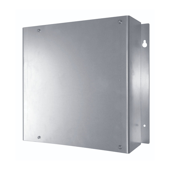
(1) After determining the attachment position, secure the
installation hardware as shown in the dimensions diagram. If
the included screws will not work for the installation, prepare
appropriate screws (such as metric ones) for use at the site.
(2) Attach the main unit and fasten the installation hardware as
illustrated.
(3) If the installation hardware is loose or appears like it will fall
out, remove the upper case on the unit and secure with
screws in the failsafe screw holes.
For your safety
This symbol refers to a hazard or unsafe procedure or practice that can result in severe personal injury or
death.
This symbol refers to a hazard or unsafe procedure or practice that can result in personal injury or product or
property damage.
Warning
Caution
Power supply line
1
(CZ-CFUNC2)
Advertisement
Table of Contents

Related Manuals for Panasonic CZ-CFUNC2


Summary of Contents for Panasonic CZ-CFUNC2
- Page 1 Instructions for the Electrical Installer (CZ-CFUNC2) For your safety Read the following instructions carefully, and carry out secure installation and electrical work. The precautions given in this manual consist of specific “Warnings” and “Cautions”. They provide important safety-related information. Be sure to strictly observe all safety procedures.
-
Page 2: Connecting The Power Supply
Wiring Always shut off the power supply (breaker) before installing or uninstalling the Communication Adaptor. Remove the two screws at the front of the unit and remove the upper case. Arrangement of the terminal board and switches Detailed terminal Detailed board illustration assembly illustration 7-segment LED... -
Page 3: Basic Wiring Diagram
Basic wiring diagram Wiring procedure (Example using an Intelligent Controller ) Wire up the Communication Adaptor control wire and Inter-unit control wiring as shown in the Inter-unit control wiring figure below. Use the shielded wire for inter-unit Outdoor unit Intelligent controller control wiring. -
Page 4: Switch Operation Overview
Setting the Communication Adaptor board The switches on the board control the adaptor numbers, turn the inter-unit control wiring connection on and off, and control other settings. 7-segment LED HOME UP DOWN SET Set key Home key Down key Monitor LED D1: red Up key D2: green... -
Page 5: Other Settings
(3) Setting the inter-unit control wiring connection on/off Repeat steps in section (2) “Adaptor number setting procedure” above. The following will display: (1.Ano.03) (When the adaptor number is 3) Press the key once so the following display appears: (2.Adyu.0) (Factory setting) Hold down the key for at least 1 second so the “0”... - Page 6 Table 1 Communication Adaptor setting items Display Setting item ( grayed in areas indicate factory setting) [1] Adaptor number setting xx = 00 to 15: adaptor number Sets the Communication Adaptor number. (1.Ano.xx) Set 1 to 7 for the Intelligent Controller, making sure the same number is not used twice. When actually communicating from a master system, the link system address LINK1 is 2n and LINK2 is 2n + 1, where n is the Communication Adaptor number.
-
Page 7: Connecting To External Equipment
Connecting to external equipment (1) External all input (No-voltage a-contact (3) Pulse meter input (No-voltage a-contact static) pulse) Equipment DI–COMMON P–COMMON Gas flow meter (*) DI 1 All stop input (*) (fuel flow meter) DI 2 All operation input (*) Power flow meter 1 (*) (Reserved) DI 3... -
Page 8: Appendix A. Connecting To An Intelligent Controller
Appendix A. Connecting to an Intelligent Controller Before making the initial settings for the Communication Adaptor, check to ensure the below operations are complete. (1) Is the air conditioner test operation complete? (2) Is the wiring for the air conditioner and the Communication Adaptor complete? To set, follow steps 1 to 5 below in sequence.