
Related Manuals for Mitsubishi Electric LY2-3750-B1T


Summary of Contents for Mitsubishi Electric LY2-3750-B1T
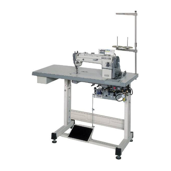
- Page 1 SINGLE-NEEDLE LOCKSTITCH UPPER AND LOWER FEED AUTOMATIC UNDERTRIMMER INDUSTRIAL SEWING MACHINE MODEL LY2-3750-B1T INSTRUCTION MANUAL A180E301P02...
- Page 2 INTRODUCTION Thank you very much for purchasing Mitsubishi industrial sewing machine. Please read this instruction manual before operating the sewing machine. Please read also “Safety Manual” , “Instruction manual for Mitsubishi Limiservo X” and operate the sewing machine correctly and safely. PRECAUTION BEFORE STARTING OPERATION Safety Precautions 1 . When turning the power on, keep your hands and fingers away from the area around/ under the needle and the area around the pulley. 2 . The power must be turned off when the machine is not used, or when the operator leaves his/her seat. 3 . The power must be turned off before tilting the machine head, installing or removing the “V” belt, adjusting the machine, or replacing parts. 4 . Avoid placing fingers, hairs, obstacles, etc. near the pulley, “V” belt, bobbin winder wheel, or motor when the machine is in operation. Injury could result. 5 . Don’t put fingers into the thread take-up lever cover, around/under the needle, or pulley when the machine is in operation. 6 . If the belt cover, the finger guard, and/or the eye guard are installed, don’t operate the machine without these safety devices.
-
Page 3: Table Of Contents
CONTENTS PREPARATION FOR OPERATION ……………………………………………… 1 1 Adjustment of the needle stopping position … …………………………………… 1 USAGE PRECAUTION ……………………………………………… 1 1 Installation of the knee lifter ……………………………………………………… 1 2 Lubrication …………………………………………………………………………… 2 3 Lubrication condition … ……………………………………………………………… 2 4 Adjustment of lubrication to the rotating hook ………………………………… 2 5 Adjustment of lubrication to the upper shaft …………………………………… 2 6 Adjustment of the oil pump … ……………………………………………………… 2 7 Periodical cleaning ……………………………………………………………………... -
Page 4: Preparation For Operation
PREPARATION FOR OPERATION 1 Adjustment of the needle stopping position 1 . Adjustment of “UP” position When the pedal is kicked down by heel, the machine stops at “UP” position. If marks deviate larger than 3 mm, adjust as follows. ( 1 ) Disconnect the plug (12pins) of cable from the machine head. ( 2 ) Run the machine and stop at “UP” position. ( 3 ) While holding the pulley, insert the “Adjusting tool” in the hole Ⓐ, then turn the tool. 2 . Adjustment of “Down” position When the pedal is “Neutral”... -
Page 5: Lubrication
USAGE PRECAUTION 2 Lubrication 5 Adjustment of lubrication to the upper shaft Fill the oil reservoir with oil up to “H” line. Oil level should be periodically checked. If oil level Remove the face plate, and adjust the lubrication is found below “L” line replenish oil to “H” line. amount by turning the upper shaft lubrication For oil, use “MC70M” specified by Mitsubishi. adjusting screw. ※ Refer MC70M : Specific gravity (15℃ ) = 0.86 (g/cm Increase :Viscosity (40℃ ) = 10.9 (mm Decrease Knee lifter pin Crank Upper shaft Adjusting screw Ⓐ Drain oil screw Ⓗ... -
Page 6: Periodical Cleaning
USAGE PRECAUTION 7 Periodical cleaning 1 . Machine ● R emove the throat plate and ● L ean the machine head and ● L ean the machine head and clean the feed dog. Reassembly clean the hook and remove remove any dust and/or lint on should be done by screwing in any dust and/or lint inside the the oil pump screen. the screw 2-3 rotations by hand bobbin case. at first, then tightening them evenly using a long-shafted screwdriver. Hook Feed bar Hook Oil pump screen Feed dog 2 . Motor Remove dust from the motor filter every one or two months. (Continued operation with the filter clogged with lint or dust may overheat the motor.) 3 . Control Box Remove dust from the connector. (If the connector is covered with dust, the machine might malfunction.) 8 Precaution for the built-in type... -
Page 7: How To Use
HOW TO USE 1 Installation of the needle Note: Before installing the needles, be sure to turn off the power. Both needles DP × 17 and Insert the needle upto the bottom of Insufficient insertion Needle distorted needle clamp and tighten the screw DB × 1 can be used. keeping the long groove side Use the timing marks as facing to the left. shown in the figure. Long groove Timing mark left side for DB×1 Timing mark for DP×17 Note:If thread snapping occurs during reverse sewing with polyester threads, it may be avoided by fitting the needle Needle bar... -
Page 8: Threading Of The Needle Thread
HOW TO USE 3 Threading of the needle thread With the thread take-up lever located at the upper most position, pass the needle thread in the order shown in the following figure. ① Thread ② ⑧ ⑥ ④ ⑥ ⑦ ④ ③ ⑧ ③ ⑤ ⑤ ⑨ ⑪ ⑩ Lead the thread rightward 4 Adjustment of feed (stitch) PUSH lever length and backstitch ● A djustment of feed (stitch) length…Adjust feed length by turning the feed length setting dial while pushing PUSH lever. -
Page 9: Adjustment Of The Needle Thread Tension
HOW TO USE 6 Adjustment of the needle thread tension ● T he needle thread tension should be adjusted on the basis of the bobbin thread tension. Thread tension nut ● A djust the needle thread tension by turning the Tighten thread tension nut. Loosen The needle thread tension can be also adjusted by changing intensity and movable range of the thread take-up spring in case of sewing the special fabric and thread. Tighten Loosen 7 Adjustment of the bobbin Screw Ⓐ thread tension Thread tension spring 1 . The bobbin thread tension can be adjusted by turning the screw Ⓐ. 8 Adjustment of the presser foot 〈Presser foot pressure〉... -
Page 10: Adjustment Of The Feed Dog Height
HOW TO USE 9 Adjustment of the feed dog 3 . After adjusting, tighten the screw Ⓐ. height Mark Eccentric pin 1 . Turn the pulley and stop it at the position where the feed lifting rock shaft crank swings Screw Ⓐ to the innermost position. 2 . Loosen the screw Ⓐ. Note: Be careful not to move the feed lifting rock shaft crank in the lateral direction. Screwdriver 3 . Adjust the feed dog height by swinging the feed lifting rock shaft fork and moving the feed bar. Position of mark on Feed dog 4 . After adjusting, fully tighten the screw Ⓐ. the eccentric pin The feed dog height is factory-adjusted to 1.0 mm. Horizontal Standard Front up... -
Page 11: B Manual Presser Bar Lifter
HOW TO USE B Manual Presser bar lifter 1 . Turn the presser bar lifter in the direction of the arrow. This raises the presser foot. C Adjustment of the feed foot and the presser foot 1 . Adjustment of alternating movement Presser bar lifter ( 1 ) The alternating movement on the feed foot and the presser foot can be adjusted by using the adjusting dial located on the top cover. Alternating movement ( 2 ) Face the desired number printed on the Matching mark adjusting dial dial to the matching mark located on the... - Page 12 HOW TO USE 3 . Installing the feed regulator bracket Should it be necessary to dismount and the feed regulator bracket and its related parts, use the procedure explained below. Feed regulator stud Note: If the feed regulator bracket is poorly Ⓑ positioned, the resultant alternating movements may be too short or long, causing defective 26.5 mm machine operation. ( 1 ) Set the clearance between special screw Ⓒ Ⓐ Ⓐ located on the regulator stud and the Feed regulator bracket 12 mm side wall of the machine arm to 26.5 mm as illustrated to the left. (Use a 26.5 mm spacer between these parts. This facilitates the operation.) ( 2 ) With the feed regulator stud held as explained in step ( 1 ) above, adjust the feed regulator bracket. This adjustment should insure a clearance of 12 mm between the periphery of pin Ⓑ located on the...
-
Page 13: D Adjustment Of The Feed Timing
HOW TO USE D Adjustment of the feed timing 1st screw Upper shaft 2nd screw 1st screw 1 . The standard position of the eccentric feed cam and eccentric feed lifting cam are illustrated to the right. 2 . To adjust the position, first open the top Upper eccentric feed Bevel gear Eccentric cover. Properly slide the eccentric cam. lifting cam for upper shaft feed cam 3 . The eccentric feed cam can also be adjusted Rubber plug Top cover by removing the rubber plug located on the top cover, and the upper eccentric feed lifting cam can also be adjusted by removing the rubber plug located on the arm. In the latter case, however, the built-in bevel Rubber plug gear is concealed; care should be taken when adjusting. - Page 14 HOW TO USE 3 . Relationship between the fixed knife and the 0.3 mm movable knife (left) edge Movable knife (left) ( 1 ) The standard position is illustrated to the (Knife edge) right. ( 2 ) If the distance (0.3 mm) is too wide, such a situation may allow for “triple” thread breakage to occur, resulting in detached needle thread Fixed knife after threads are cut. Also, if it is too narrow, such a situation may lead to unexpectedly uncut threads. Please keep this in mind. Screw Ⓐ ( 3 ) The adjustment necessary in step ( 2 ) can be done by correctly installing the fixed knife bracket unit or correctly mounting the fixed knife.
- Page 15 HOW TO USE 6 . Installing the thread trimmer cam ( 1 ) Face the 2nd timing mark Ⓐ (Green) Matching mark Ⓐ located on the pulley to the matching mark on the arm. ( 2 ) With the thread trimmer solenoid activated, turn the thread trimmer cam forward until the cam makes contact with the roller. Thread trimmer cam Then, set the cam. Thread trimmer cam 0.5 to 1.0 mm ( 3 ) With the thread trimmer solenoid Roller deactivated, allow the cam follower crank ( 2 ) to return to its original position. This should create a clearance of 0.5 to 1.0 mm between the cam and roller end. This distance is standard. 0.6 mm Note: The standard position of cam follower crank (2) before activation is illustrated...
-
Page 16: F The Rotating Hook, Bobbin Case, And Bobbin
HOW TO USE 8 . Adjustment of the needle thread tension release ( 1 ) With the thread trimmer solenoid activated, Thread trimmer solenoid adjustment should be such that the thread tension discs located on the needle thread tension regulator are separated from each other by about 1 mm. Increase the opening amount ( 2 ) Adjustment can be done in this way: Ⓐ Loosen nut Ⓐ and properly move the Flexible wire flexible wire. ( 3 ) Move the flexible wire to the right to increase the opening amount. Note: If the thread tension discs are too narrowly, the needle thread may 1 mm be liable to be broken, resulting in detached needle thread. Also, if the space between the discs is too wide, the excessive blank space between the discs... -
Page 17: Specifications
SPECIFICATIONS LY2-3750-B1T Specifications Model LY2-3750-B1T Specifications Application Heavy material Max. sewing speed (rpm) 2,000 Stitch length (mm) 0 to 8 Needle bar stroke (mm) 38.0 Thread take-up lever stroke (mm) 73.0 Alternating movement (mm) 2.0 to 5.0 (feed foot) Alternating movement changing system Dial (One-touch) Feed dog height (mm) 1.0 Hand 6.0 Presser foot stroke (mm) Knee 16.0 Needle DP × 17 #22 (DB × 1 #22) Hook (vertical rotating hook) Large Bobbin case With racing prevention spring Bobbin Made of steel for thread trimmer Lubrication system Automatic lubrication... - Page 20 Printed in Japan...