
Related Manuals for Mitsubishi Electric LY2-3310-B1T


Summary of Contents for Mitsubishi Electric LY2-3310-B1T
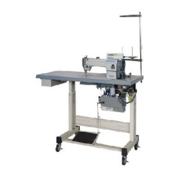
- Page 1 SINGLE-NEEDLE LOCKSTITCH UPPER AND LOWER FEED AUTOMATIC UNDERTRIMMER INDUSTRIAL SEWING MACHINE MODEL LY2-3310-B1T INSTRUCTION MANUAL A180E388P03...
- Page 2 INTRODUCTION Thank you very much for purchasing Mitsubishi industrial sewing machine. Please read this instruction manual before operating the sewing machine. Please read also “Safety Manual” , “Instruction manual for Mitsubishi Limiservo X” and operate the sewing machine correctly and safely. PRECAUTION BEFORE STARTING OPERATION Safety Precautions 1 . When turning the power on, keep your hands and fingers away from the area around/ under the needle and the area around the pulley. 2 . The power must be turned off when the machine is not used, or when the operator leaves his/her seat. 3 . The power must be turned off before tilting the machine head, installing or removing the “V” belt, adjusting the machine, or replacing parts. 4 . Avoid placing fingers, hairs, obstacles, etc. near the pulley, “V” belt, bobbin winder wheel, or motor when the machine is in operation. Injury could result. 5 . Don’t put fingers into the thread take-up lever cover, around/under the needle, or pulley when the machine is in operation. 6 . If the belt cover, the finger guard, and/or the eye guard are installed, don’t operate the machine without these safety devices.
-
Page 3: Table Of Contents
CONTENTS PREPARATION FOR OPERATION ……………………………………………… 1 1 Adjustment of the needle stopping position … …………………………………… 1 USAGE PRECAUTION ……………………………………………… 2 1 Lubrication …………………………………………………………………………… 2 2 Adjustment of lubrication to the rotating hook ………………………………… 2 3 Periodical cleaning …………………………………………………………………… 3 4 Precaution for the built-in type detector ………………………………………… 4 5 Installation of the belt cover ……………………………………………………… 4 6 Precaution on operation …………………………………………………………… 4 HOW TO USE ………………………………………………... -
Page 4: Preparation For Operation
PREPARATION FOR OPERATION 1 Adjustment of the needle stopping position 1 . Adjustment of “UP” position When the pedal is kicked down by heel, the machine stops at “UP” position. If marks deviate larger than 3 mm, adjust as follows. ( 1 ) Disconnect the plug (12pins) of cable from the machine head. ( 2 ) Run the machine and stop at “UP” position. ( 3 ) While holding the pulley, insert the “Adjusting tool” in the hole Ⓐ, then turn the tool. 2 . Adjustment of “Down” position When the pedal is “Neutral”... -
Page 5: Usage Precaution
USAGE PRECAUTION 1 Lubrication Supply the oil to the tank of the bed Fill oil up to the line when the oil would come ● P our oil up to the arrow position before starting bottom level. operation. …About 3 cc …5, 6 drops Hole for supply …1, 2 drops Line For oil, use “Pulley SF oil” specified by Mitsubishi. ※ Refer Pulley SF oil : Specific gravity (15℃ ) = 0.86 (g/cm :Viscosity (40℃ ) = 18.0 (mm ● W hen a new sewing machine is used for the first time, or sewing machine left out of use for considerably long time is used again, replenish a suitable amount of oil to the portions indicated by arrows in the below figure. -
Page 6: Periodical Cleaning
USAGE PRECAUTION 3 Periodical cleaning 1 . Machine ● Remove the throat plate and clean the ● Lean the machine head and clean the hook feed dog. Reassembly should be done by and remove any dust and /or lint inside the screwing in the screw 2-3 rotations by hand bobbin case. at first, then tightening them evenly using a long-shafted screwdriver. Hook Hook Feed bar Feed dog 2 . Motor Remove dust from the motor filter every one or two months. (Continued operation with the filter clogged with lint or dust may overheat the motor.) 3 . Control Box Remove dust from the connector. (If the connector is covered with dust, the machine might malfunction.) — 3 —... -
Page 7: Precaution For The Built-In Type Detector
USAGE PRECAUTION 4 Precaution for the built-in type detector 1 . Since the optical type detecting element is used in the detector, prevent dust or oil from sticking to the detecting plate when the sewing machine pulley is removed for adjustment. If they have stuck, wipe them off with soft cloth carefully so that the surface is not scratched, do not let oil permeate the clearance on the detecting plate. 2 . In case of disconnection of the position detector connector, running off the belt or complete constraint and over load, the motor is automatically turned off after predetermined time to prevent burning of the motor. (However, in case of half-constraint and over load, the power may not be turned off.) After the failure is eliminated, the normal operation is resumed by turning off the power once then turning on again. The same operation occurs for the detector malfunction or the line breakage. 5 Installation of the belt cover 1 . Install the belt cover on the machine side for safety. Refer to the provided instruction document contained in the same package. 2 . Install the belt cover on the motor side for safety. 6 Precaution on operation ( 1 ) When the power is turned on or off, keep foot away from the pedal. -
Page 8: How To Use
HOW TO USE 1 Installation of the needle Note: Before installing the needles, be sure to turn off the power. Both needles DP × 17 and Insert the needle upto the bottom of Insufficient insertion Needle distorted needle clamp and tighten the screw DB × 1 can be used. keeping the long groove side facing Use the timing marks as to the left. shown in the figure. Long groove Timing mark left side for DB×1 Timing mark for DP×17 Note:If thread snapping occurs during reverse sewing with polyester threads, it may be avoided by fitting the needle Needle bar... -
Page 9: Threading Of The Needle Thread
HOW TO USE 3 Threading of the needle thread With the thread take-up lever located at the upper most position, pass the needle thread in the order shown in the following figure. ① Touch back switch 5 Balance of threads tension ② ⑦ A ○ ⑥ Balanced tension ⑧ ③ ⑨ B × Tight the needle thread tension or ⑩ loose the bobbin thread tension ④ ⑤ ⑪ C × Loose the needle thread tension or tight the bobbin thread tension 4 Adjustment of feed (stitch) length and backstitch 6 Adjustment of the needle thread tension... -
Page 10: Adjustment Of The Bobbin Thread Tension
HOW TO USE 7 Adjustment of the bobbin 9 Adjustment of the feed dog thread tension height 1 . The bobbin thread tension can be adjusted 1 . Turn the pulley and stop it at the position where the feed lifting rock shaft crank (right) by turning the screw Ⓐ. swings to the innermost position. 2 . Loosen the screw Ⓐ. Tighten Note: Be careful not to move the feed lifting Loosen rock shaft crank (right) in the lateral direction. Screw Ⓐ 3 . Adjust the feed dog height by swinging the feed lifting rock shaft crank (left) and moving Thread tension spring the feed bar. 4 . After adjusting, fully tighten the screw Ⓐ. -
Page 11: Adjustment Of The Feed Foot And The Presser Foot
HOW TO USE : Adjustment of the feed foot and the presser foot Ⓐ 1 . To change the balance of the alternating movements between the feed foot and presser foot ( 1 ) For example, to increase the rise of the feed foot, and decrease the rise of the presser foot. ①Turn the pulley until the presser foot is slightly raised from the throat plate. ②Loosen the set screw Ⓐ (on the right side) located on the feed lifting rock shaft crank (right). ③The built-in spring pulls down the presser foot until it makes contact with the throat plate. Then, tighten the set screw Ⓐ. -
Page 12: A To Handle Thread At The Start Of Sewing
HOW TO USE A To handle thread at the start of Needle thread sewing 1 . In the case of open sewing: Bobbin thread When the needle thread is not held by the presser foot during sewing, the end of the needle thread is stitched onto the reverse side of the cloth, thus enhancing a sewing finish. Needle thread Needle thread Slowly start to take up a few stitches at the Cloth Cloth beginning so as to prevent the needle thread from being off out of the needle. 2 . When the needle thread is held by the presser foot: The end of the needle thread remains on the surface of the cloth. - Page 13 HOW TO USE 3 . Relationship between the fixed knife and the 0.3 mm Movable knife (left) movable knife (left) edge ( 1 ) The standard position is illustrated to the (Knife edge) right. ( 2 ) If the distance (0.3 mm) is too wide, such a situation may allow for “triple” thread breakage to occur, resulting in detached needle thread Fixed knife after threads are cut. Also, if it is too narrow, such a situation may lead to unexpectedly Screw Ⓐ uncut threads. Please keep this in mind. ( 3 ) The adjustment necessary in step ( 2 ) can be done by correctly installing the fixed knife bracket unit or correctly mounting Fixed knife ...
- Page 14 HOW TO USE 6 . Installing the thread trimmer cam Matching mark Ⓐ ( 1 ) Face the 2nd timing mark Ⓐ located on the pulley to the matching mark on the arm. ( 2 ) With the thread trimmer solenoid activated, turn the thread trimmer cam forward until the cam makes contact with the roller. Then, set the cam. ( 3 ) With the thread trimmer solenoid Thread trimmer cam Thread trimmer cam deactivated, allow the cam follower crank 0.5 to 1.0 mm Roller ( 2 ) to return to its original position. This should create a clearance of 0.5 to 1.0 mm between the cam and roller end. This distance is standard. 0.6 mm Note: The standard position of cam follower crank (2) before activation is illustrated to the right. If this position has been...
-
Page 15: C Adjustment Of The Gap Between The Pulley And The Machine Head
HOW TO USE 8 . Adjustment of the needle thread tension release Thread trimmer solenoid ( 1 ) With the thread trimmer solenoid activated, adjustment should be such that the thread tension discs located on the needle thread tension regulator are separated from each other by about 1 mm. ( 2 ) Adjustment can be done in this way: Increase the opening amount Loosen nut Ⓐ and properly move the Ⓐ Flexible wire flexible wire. ( 3 ) Move the flexible wire to the right to increase the opening amount. Note: If the thread tension discs are too narrowly, the needle thread may 1 mm be liable to be broken, resulting in detached needle thread. Also, if the space between the discs is too wide, the... -
Page 16: Specifications
SPECIFICATIONS LY2-3310-B1T Specifications Model LY2-3310-B1T Specifications Application Heavy material Max. sewing speed (rpm) 2,000 Stitch length (mm) 0 to 8 Needle bar stroke (mm) 38.0 Thread take-up lever stroke (mm) 73.0 Alternating movement (mm) 2.0 to 5.0 (feed foot) Feed dog height (mm) 1.0 Hand 6.0 Presser foot stroke (mm) Knee 13.0 Needle DP × 17 #22 (DB × 1 #22) Hook (vertical rotating hook) Large Bobbin case With racing prevention spring Bobbin Made of steel for thread trimmer Manual lubrication (The hook is supplied Lubrication system with oil automatically from the tank) Thread trimmer... - Page 20 Printed in Japan...