Table of Contents
Advertisement
SmartLi Quick Guide
Issue: 06
Part Number: 31500BED
Date: 2020-03-13
1
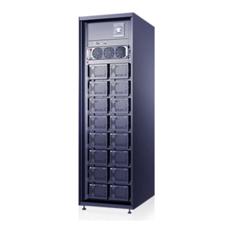
Overview
Model
SmartLi-512V-80AH-F
SmartLi-512V-80AH-S
Front View
Battery circuit breaker
Monitoring module
Battery control unit
End pressure gauge
Battery module
1. Before installation, read the user manual carefully to get familiar with product information and
safety precautions.
2. Use insulated tools during installation and operation.
3. Only Huawei engineers or engineers certified by Huawei are allowed to install, commission, and
maintain the battery cabinet. Otherwise, personal injury or equipment damage may occur, and
the resulting battery cabinet faults are beyond the warranty scope of Huawei.
4. This document describes how to install a single battery cabinet. For details about how to install
parallel systems, contact Huawei technical support.
Capacity
Weight
< 750
80 Ah
kg
Fuse
Copyright © Huawei Technologies Co., Ltd. 2020. All rights reserved.
Dimensions (H x W x D)
2000 mm x 600 mm x 850
mm
Rear
View
MDU
Auxiliary
wrench
Fire-trace
cylinder
Fuse
1
Configuration type
With an LCD
Without an LCD
tube
Fire
Advertisement
Table of Contents

Related Manuals for Huawei SmartLi Series


Summary of Contents for Huawei SmartLi Series
- Page 1 2. Use insulated tools during installation and operation. 3. Only Huawei engineers or engineers certified by Huawei are allowed to install, commission, and maintain the battery cabinet. Otherwise, personal injury or equipment damage may occur, and the resulting battery cabinet faults are beyond the warranty scope of Huawei.
- Page 2 Installing a Fire Cylinder 1. Remove the rear panel of the cabinet. 2. Remove the fire cylinder. a) Remove the fire cylinder fastener. b) Take out the fire cylinder. 3. Check the fire cylinder and all components for any damage, abrasion, or corrosion. If there is any visible abrasion or corrosion, replace the damaged components and all corroded components.
- Page 3 7. Install the fire-trace tube on the fire cylinder. Do not bend or twist the fire-trace tube or bind the tube using cable ties. Otherwise, the fire cylinder may fail. a. Clamp the end of the fire-trace tube to the threaded nozzle using a pipe holder. Hold the pipe holder close to the end to avoid bending the tube during pipe...
- Page 4 9. Install a dry contact cable. a. Connect one end of a cable to the dry contact cable of the fire cylinder. b. Secure the cable, as shown in the following figure. c. Connect the other end of the dry contact cable to the DI_1 port on the dry contact expansion card of the UPS.
-
Page 5: Installing A Cabinet
Installing a Cabinet Secured Installation 1. Determine the position for installing the cabinet. 5. Open the front door, and remove the four Mark mounting holes based on the drawings rubber plugs from the bottom of the (unit: mm). cabinet. 6. Insert four M12x115 expansion bolts into the expansion bolt holes in the floor, and tighten the expansion bolts. - Page 6 Cable Connection Reference Cable Connection Reference • Prepare cables away from the cabinets to prevent scraps from falling inside. Cable scraps may ignite and cause personal injury or device damage. • After cables have been installed, clean the cabinets in a timely manner. Keep the cabinets and surrounding environment clean and tidy.
- Page 7 3. Connect the ground cable. The 70 mm ground cable is recom mended. Installing Battery Modules and Cables 1. Pull out the battery control unit for about 10 cm 2. Install battery modules. 1. Install the battery modules from bottom to top and from left to right to prevent falling over due to imbalance.
- Page 8 3. Remove front cover from the battery module, 4. Install battery communications cables. and install battery baffle plate. 1. Communications cables between the battery modules and the battery control unit are preinstalled inside the cabinet. 2. Connect cables between the battery modules and then connect the cables to the battery control unit.
- Page 9 5. Open the battery terminal protective cover, install battery copper bars and cables. 1. During installation, wear insulation gloves and use insulated tools. 2. Battery cables are preinstalled inside the cabinet. 3. Install copper bars between the battery modules, and then install cables between the battery modules and the battery control unit.
-
Page 10: Installing Output Cables
7. Reinstall the battery control unit. Installing Output Cables 1. Install power cables. 2. Install a communications cable to the UPS. -
Page 11: Combining Cabinets
Combining Cabinets 1. The SmartLi supports the combination of up to five cabinets. 2. When multiple cabinets are connected in parallel, only the basic cabinet has an LCD. 3. When cabinets are combined, a battery bus bar box (BBB box) is required. For details about how to install a BBB box, see PDU8000-(0630,1250, 2000) DCV8-BGA001 BBB Box User Manual. - Page 12 4. Connect battery cables. 5. Connect communications cables. MUE05A The numbers of cabinets in a parallel system depend on the connection of communications cables. After the communications cables are connected according to the preceding figure, the cabinets are numbered 1, 2, 3, 4, and 5 from top to bottom.
-
Page 13: Verifying The Installation
Verifying the Installation 1. Check that there is no foreign matter at the top 5. Do not remove the dustproof cover before and bottom of the cabinets, copper bars, power-on to prevent dust inside the SmartLi. switches, and the rear of units. Top dustproof cover 2. - Page 14 2. Press and hold the POWER ON/OFF button on the battery control unit for more than 2s. The green indicator of the battery control unit blinks at 4 Hz. • The BCB off alarm is displayed on the UPS LCD and SmartLi LCD. No action is required. After the battery circuit breaker is closed, the alarm is automatically cleared.
-
Page 15: Powering Off
4. After the green indicator of the battery control unit blinks at 10 Hz, turn on the battery circuit breaker on the SmartLi. 5. When multiple SmartLi cabinets are combined: 1) If the green indicator of one battery control unit blinks at 10 Hz, turn on the battery circuit breaker on any SmartLi. - Page 16 Scan here for technical support (carrier): Huawei App Store Scan here for more documents: Support-E Support WeChat You can also log in to Huawei technical support website: https://support.huawei.com/enterprise https://support.huawei.com Huawei Technologies Co., Ltd. Huawei Industrial Base, Bantian, Longgang Shenzhen 518129 People's Republic of China...