Table of Contents
Advertisement
Available languages
Available languages
Quick Links
Advertisement
Chapters
Table of Contents

Related Manuals for Brother PRCL1


Summary of Contents for Brother PRCL1
-
Page 3: Table Of Contents
Cylinder Frame User's Guide INCLUDED ACCESSORIES IMPORTANT NOTE EMBROIDERY SAMPLES USING THE CYLINDER FRAME DIAMETER AND DEPTH OF BAGS AND CYLINDRICAL ITEMS THAT CAN BE EMBROIDERED Bags (purses or cases) ......................4 Knit ribbing on cuffs (such as on golf club covers) .............. 4 Cylindrical items (such as pant legs or shirts) .............. -
Page 4: Included Accessories
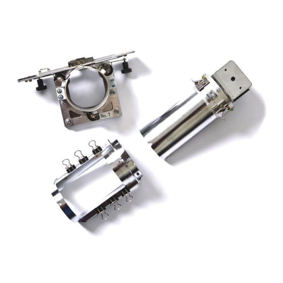
Included accessories Check that the following cylinder frame, cylinder frame driver, cylinder frame mounting jig and the accessories are included. If any item is missing or damaged, contact your authorized retailer. Part Name Cylinder frame with 8 clips (Embroidering area (90 mm (wide) × 80 mm (high))) Cylinder frame driver and 4 thumb screws (Attach the cylinder frame driver to the carriage in order to use the cylinder frame.) Cylinder frame mounting jig... -
Page 5: Important Note
By using the cylinder frame, patterns can be Important note embroidered onto bags and cylindrical items. The procedures for using the cylinder frame are ● Do not place floppy disks or magnetic cards described below. near the cylinder frame driver. The cylinder frame driver is equipped with extremely Embroidery samples using strong magnets, which may affect magnetic... -
Page 6: Diameter And Depth Of Bags And Cylindrical Items That Can Be Embroidered
■ Knit ribbing on cuffs (such as on golf club covers) Diameter and depth of bags and cylindrical items that can be embroidered The items embroidered using the cylinder frame must have the diameter and depth shown below. The diameter refers to the width of the bag or cylindrical item, and the depth refers to the height of the bag or cylindrical item. -
Page 7: Fabrics
Loosen and remove the two thumb screws, Fabrics and then remove the embroidery frame holder. For best results, it is recommended to use the following types of fabrics. • 100% cotton • 35% cotton/65% polyester • 80% wool/20% nylon • 15% wool/85% acrylic Fabrics that are difficult to hoop, wrinkle easily or shrink are not recommended to be used with the cylinder frame. - Page 8 Pass the machine bed through the ring of the Insert the pins on the X carriage into the cylinder frame driver. holes in the mounting plate of the cylinder frame driver. Machine bed Gap in the mounting plate Pins on the X carriage Holes in the mounting plate of the cylinder Note frame driver...
-
Page 9: Adjusting The Cylinder Frame Driver (Only When Used For The First Time)
■ Adjusting the cylinder frame driver (only when Using the enclosed Allen wrench (2.5 mm), used for the first time) turn the two hexagonal screws one turn in the direction of the arrow to loosen them. When the hexagonal screws are loosened, the fitting in the ring is lowered. -
Page 10: Installing The Needle Plate Spacer
■ Installing the needle plate spacer Using the enclosed Allen wrench (3 mm), turn the four hexagonal screws outside the Attach the needle plate spacer (included with the ring one turn in the direction of the arrow to machine) to the needle plate. loosen them. -
Page 11: Installing The Cylinder Frame
Securely clamp the mounting bracket onto Installing the cylinder frame the mounting surface, and then tighten the thumb screw. Hoop the fabric in the cylinder frame, and then attach the cylinder frame to the cylinder frame driver. ■ Hooping the fabric in the cylinder frame Attach the cylinder frame to the cylinder frame mounting jig. - Page 12 Position the stabilizer into the stabilizer Pull the ends of the fabric out from the holder on the cylinder frame. center to remove any slack. Be careful not to shift the center of the design placement. Use the clips to secure the fabric and Stabilizer holder stabilizer.
-
Page 13: Attaching The Cylinder Frame To The Machine
Remove the cylinder frame from the cylinder Attach the cylinder frame to the cylinder frame mounting jig. frame driver. Press on the two holders on the mounting jig with both thumbs, and then pull the cylinder Note frame straight off in the direction of the arrow ●... -
Page 14: Removing The Cylinder Frame
■ Removing the cylinder frame Installing the embroidery After finishing sewing, remove the cylinder frame, then the fabric. frame holder Remove the cylinder frame from the cylinder After removing the needle plate spacer and the frame driver. cylinder frame driver, re-attach the embroidery frame holder. - Page 15 Remove the two upper thumb screws. Align the hole in the L-shaped mounting bracket for the cylinder frame driver with the centerline of the guiding plate, insert the two thumb screws removed in step into the holes at the top, and then tighten the thumb screws.
-
Page 16: Additional Digitizing Information
Secure the embroidery frame holder with Additional digitizing the two thumb screws. information In order to prevent pattern misalignment due to wrinkled or stretched fabric, observe the following precautions when creating embroidery data for the cylinder frame. Sew underlay stitches. Use the thumb screws included with the embroidery machine (thumb screws removed in step... - Page 17 When sewing outlines of patterns, make sure that the stitch width of the satin stitching is at least 3 mm, and that the stitching overlaps the fabric by at least 1.5 mm. Also, make sure that there are no jumps of long stitches in the outlining on each region or letter.
- Page 19 Manuel de l'utilisateur du cadre cylindrique ACCESSOIRES FOURNIS REMARQUE IMPORTANTE ECHANTILLONS DE BRODERIE AVEC LE CADRE CYLINDRIQUE DIAMÈTRE ET PROFONDEUR DES SACS ET PIÈCES CYLINDRIQUES À BRODER Sacs (bourses ou étuis) ......................20 Côtes en tricot sur manchettes (capuchons pour club de golf) ..........20 Pièces cylindriques (jambes de pantalon ou chemises) ............20 TISSUS PRÉPARATION DU CADRE CYLINDRIQUE...
-
Page 20: Accessoires Fournis
Accessoires fournis Vérifiez que le cadre cylindrique, son support, son dispositif d'assemblage et les accessoires sont inclus. Si un élément manque ou est endommagé, contactez un revendeur agréé. N° Nom de la pièce Cadre cylindrique avec 8 attaches (Zone de broderie (90 mm (largeur) × 80 mm (hauteur))) Support du cadre cylindrique et 4 vis à... -
Page 21: Remarque Importante
Le cadre cylindrique vous permet de broder des Remarque importante motifs sur des sacs et des pièces cylindriques. Les procédures d'utilisation du cadre cylindrique sont ● Ne placez pas de disquettes ou de cartes décrites ci-dessous. magnétiques à proximité du support du cadre cylindrique. -
Page 22: Diamètre Et Profondeur Des Sacs Et Pièces Cylindriques Àbroder
■ Côtes en tricot sur manchettes (capuchons pour club de golf) Diamètre et profondeur des sacs et pièces cylindriques à broder Les pièces brodées avec le cadre cylindrique doivent avoir le diamètre et la profondeur indiqués ci- dessous. Le diamètre correspond à la largeur du sac ou de la pièce cylindrique et la profondeur à... -
Page 23: Tissus
Desserrez et retirez les deux vis à serrage à Tissus main, puis retirez le cadre de support de broderie. Pour des résultats optimaux, il est recommandé d'utiliser les types de tissus suivants. • 100 % coton • 35 % coton/65 % polyester •... - Page 24 Faites passer le plateau de la machine dans Insérez les ergots du chariot X dans les trous le cercle du support du cadre cylindrique. situés sur la plaque d'assemblage du support du cadre cylindrique. Plateau de la machine Trou sur la plaque d'assemblage Ergots du chariot X Trous situés sur la plaque d'assemblage du Remarque...
-
Page 25: Réglage Du Support Du Cadre Cylindrique (Uniquement Lors De La Première Utilisation)
■ Réglage du support du cadre cylindrique A l'aide de la clé Allen (2,5 mm) fournie, (uniquement lors de la première utilisation) dévissez les deux vis hexagonales d'un tour dans le sens de la flèche. Lorsque les vis hexagonales sont desserrées, le raccord du cercle s'abaisse. -
Page 26: Installation De La Cale D'épaisseur De La Plaque À Aiguille
■ Installation de la cale d'épaisseur de la plaque à A l'aide de la clé Allen (3 mm) fournie, dévissez les quatre vis hexagonales à aiguille l'extérieur du cercle d'un tour dans le sens Fixez la cale d'épaisseur (fournie avec la de la flèche. -
Page 27: Installation Du Cadre Cylindrique
Fixez solidement le support d'assemblage sur Installation du cadre cylindrique la surface, puis serrez la vis à serrage à main. Placez le tissu dans le cadre cylindrique et fixez ce dernier au support. ■ Mise en place du tissu dans le cadre cylindrique Fixez le cadre cylindrique sur le dispositif d'assemblage. - Page 28 Placez le matériau stabilisateur sur le support Tirez les extrémités du tissu à partir du correspondant sur le cadre cylindrique. centre de manière à bien le tendre. Veillez à ne pas décaler le centre du motif. Utilisez les attaches pour fixer le tissu et le Support pour matériau stabilisateur matériau stabilisateur.
-
Page 29: Fixation Du Cadre Cylindrique Sur La Machine
Retirez le cadre cylindrique du dispositif Fixez le cadre cylindrique sur son support. d'assemblage. Appuyez sur les deux supports du dispositif Remarque d'assemblage avec les deux pouces et retirez ● Lorsque vous fixez le cadre cylindrique sur le cadre cylindrique dans le sens de la flèche la machine, comme illustré. -
Page 30: Retrait Du Cadre Cylindrique
■ Retrait du cadre cylindrique Installation du support du Une fois la broderie terminée, retirez le cadre cylindrique et le tissu. cadre de broderie Retirez le cadre cylindrique de son support. Après le retrait de la cale d'épaisseur de la plaque à Appuyez sur les deux supports à... - Page 31 Retirez les deux vis à serrage à main Alignez le trou situé sur le support supérieures. d'assemblage en L du support du cadre cylindrique sur la ligne centrale de la plaque de guidage, insérez les deux vis à serrage à main retirées à...
-
Page 32: Informations De Numérisation Complémentaires
Fixez le support du cadre de broderie à Informations de numérisation l'aide des deux vis à serrage à main. complémentaires Afin d'éviter que les motifs ne soient décalés en raison d'un tissu froissé ou tendu, respectez les précautions suivantes lors de la création de données de broderie pour le cadre cylindrique. - Page 33 Lorsque vous brodez les contours des motifs, assurez-vous que la largeur des points plumetis est d'au moins 3 mm et que les points recouvrent le tissu d'au moins 1,5 mm. Vérifiez également qu'il n'y a pas de sauts de longs points dans les contours de chaque zone ou lettre.
- Page 35 Guía del usuario del bastidor cilíndrico ACCESORIOS INCLUIDOS NOTA IMPORTANTE MUESTRAS DE BORDADOS CON EL BASTIDOR CILÍNDRICO DIÁMETRO Y PROFUNDIDAD DE LOS BOLSOS Y PIEZAS CILÍNDRICAS QUE SE PUEDEN BORDAR Bolsos (bolsos de mano o de viaje) ..................36 Punto acanalado en puños (como en fundas para palos de golf) ........36 Piezas cilíndricas (como perneras o mangas de camisa) ............36 TEJIDOS PREPARACIÓN PARA EL USO DEL BASTIDOR CILÍNDRICO...
-
Page 36: Accesorios Incluidos
Accesorios incluidos Compruebe que están incluidos el bastidor cilíndrico, la guía del bastidor cilíndrico, el dispositivo de montaje del bastidor cilíndrico y los accesorios siguientes. Si falta algún componente o alguno estuviera dañado, póngase en contacto con su distribuidor autorizado. Nº... -
Page 37: Nota Importante
Con el bastidor cilíndrico, puede bordar diseños en Nota importante bolsos y piezas cilíndricas. A continuación se describen los procedimientos para la utilización de ● No coloque disquetes ni tarjetas magnéticas este bastidor. cerca de la guía del bastidor cilíndrico. Esta guía está... -
Page 38: Diámetro Y Profundidad De Los Bolsos Y Piezas Cilíndricas Que Se Pueden Bordar
■ Punto acanalado en puños (como en fundas para palos de golf) Diámetro y profundidad de los bolsos y piezas cilíndricas que se pueden bordar Las piezas que se borden con el bastidor cilíndrico deben tener el diámetro y la profundidad que se muestran a continuación. -
Page 39: Tejidos
Afloje y extraiga los dos tornillos de Tejidos mariposa y, a continuación, retire el soporte del bastidor. Para obtener los mejores resultados, se recomienda utilizar los siguientes tipos de tejidos: • 100% algodón • 35% algodón / 65% poliéster • 80% lana / 20% nylon •... - Page 40 Pase la plataforma de la máquina por el aro Inserte las patillas del carro X en los orificios de la guía del bastidor. de la placa de montaje de la guía del bastidor. Plataforma de la máquina Hueco en la placa de montaje Patillas del carro X Orificios de la placa de montaje de la guía del Nota...
-
Page 41: Ajuste De La Guía Del Bastidor Cilíndrico (Sólo Cuando Se Utiliza Por Primera Vez)
■ Ajuste de la guía del bastidor cilíndrico (sólo Con la llave Allen (2,5 mm) suministrada, cuando se utiliza por primera vez) gire los dos tornillos hexagonales una vuelta en la dirección de la flecha para aflojarlos. Cuando los tornillos hexagonales están flojos, se baja el ajuste en el aro. -
Page 42: Colocación Del Separador De La Placa De La Aguja
■ Colocación del separador de la placa de la aguja Con la llave Allen (3 mm) suministrada, gire los cuatro tornillos hexagonales situados por Coloque el separador (suministrado con la fuera del aro una vuelta en la dirección de la máquina) en la placa de la aguja. -
Page 43: Colocación Del Bastidor Cilíndrico
Sujete con firmeza la abrazadera de montaje Colocación del bastidor cilíndrico en la superficie y apriete el tornillo de mariposa. Coloque el tejido en el bastidor cilíndrico y, a continuación, coloque el bastidor en la guía del bastidor. ■ Colocación del tejido en el bastidor cilíndrico Coloque el bastidor en el dispositivo de montaje del bastidor. - Page 44 Coloque el estabilizador en el soporte Tire de los extremos del tejido hacia fuera correspondiente en el bastidor. desde el centro para eliminar cualquier holgura. Tenga cuidado de no desplazar el centro de la posición del diseño. Soporte del estabilizador Utilice las pinzas para sujetar el tejido y el •...
-
Page 45: Colocación Del Bastidor Cilíndrico En La Máquina
Retire el bastidor del dispositivo de montaje. Coloque el bastidor en la guía del bastidor. Presione con ambas manos sobre los dos soportes del dispositivo de montaje y, a Nota continuación, saque el bastidor en la ● Al colocar el bastidor cilíndrico en la dirección de la flecha mostrada en la máquina: ilustración. -
Page 46: Extracción Del Bastidor Cilíndrico
■ Extracción del bastidor cilíndrico Colocación del soporte del Después de terminar de coser, quite el bastidor y, a continuación, el tejido. bastidor de bordado Retire el bastidor de la guía del bastidor. Después de extraer el separador de la placa de la Presione con ambas manos los dos soportes aguja y la guía del bastidor, vuelva a colocar el soporte del bastidor de bordado. - Page 47 Saque los dos tornillos de mariposa Alinee el orificio de la abrazadera de superiores. montaje en forma de L de la guía del bastidor con la línea central de la placa de referencia, coloque los dos tornillos de mariposa quitados en el paso en los orificios de la parte superior y, a continuación, apriételos.
-
Page 48: Información Digitalizada Adicional
Ajuste el soporte del bastidor con los dos Información digitalizada tornillos de mariposa. adicional Para evitar que los diseños no queden alineados debido a tejidos arrugados o estirados, tome las siguientes medidas de precaución cuando cree datos de bordado para el bastidor cilíndrico. Cosa puntadas de refuerzo. - Page 49 Cuando cosa contornos de diseños, asegúrese de que la anchura de la puntada para satén sea al menos de 3 mm y que la costura se solape al tejido al menos 1,5 mm. Compruebe también que no hay saltos de puntadas largas en el contorno de cada zona o letra.
- Page 52 English French Spanish 884-T03 XE2316-001 Printed inTaiwan...