Sony Walkman WM-EX9 Service Manual
Hide thumbs
Also See for Walkman WM-EX9:
- Operating instructions (2 pages) ,
- Operating instructions manual (9 pages)
Table of Contents
Advertisement
SERVICE MANUAL
Ver 1.1 1999. 01
Ver 1.1 1999. 01
Dolby noise reduction manufactured under license from Dolby Labo-
ratories Licensing Corporation.
"DOLBY" and the double-D symbol a are trademarks of Dolby
Laboratories Licensing Corporation.
System
Compact cassette stereo
Frequency response (Dolby NR off)
Playback: 30 - 18,000 Hz
Headphones 2 jack
Output
Load impedance 8 - 300 ohms
4 mW + 4 mW (32 Ω)
Maximum output level
Power requirements
DC 1.5 V
Nickel metal hydride rechargeable
battery (supplied)
One R6 (size AA) batteries
(negative ground)
Battery life (Approx. hours)
Rechargeable NH-14WM
40
fully charged
Rechargeable NC-6WM
18
fully charged
Sony alkaline LR6 (WM)
60
Rechargeable NH-14WM
100
Sony alkaline LR6 (WM)
used together
Rechargeable NC-6WM
78
Sony alkaline LR6 (WM)
used together
Approx. 77.7 × 108 × 19.6 mm
Dimensions (w/h/d)
× 4
(3
1/8
projecting parts and controls
Mass
Approx. 140 g / Approx. 205 g
(5.0
/ 7.3
oz
incl. rechargeable battery
and a cassette
MICROFILM
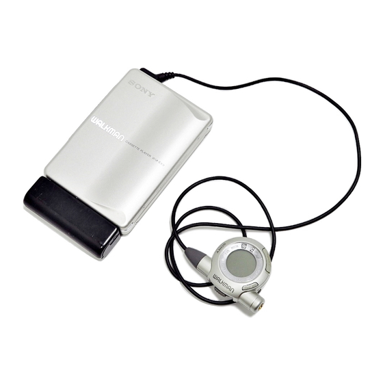
Photo: Gold type
SPECIFICATIONS
×
in.)
3/8
25/32
)
oz
WM-EX9
Model Name Using Similar Mechanism
Tape Transport Mechanism Type
Supplied accessories
Battery charger BC-7DC (1)
(US model)
Battery charger BC-7DY (1)
(AEP, French model)
Battery charger BC-7HT (1)
(E, Tourist model)
Battery charger BC-7S (1)
(UK model)
Battery charger BC-9HR (1)
(Korea model)
Rechargeable battery NH-14WM (1)
(E, Tourist, Korea model)
Rechargeable battery NC-6WM (1)
(Except E, Tourist, Korea model)
Rechargeable battery case (1)
Dry battery case (1)
Stereo headphones with remote control
MDR-ED132SP + RM-WME21L (1)
Carrying pouch (1)
AC plug adaptor (1) (E, Tourist model)
Design and specifications are subject to change without notice.
– 1 –
US Model
AEP Model
UK Model
E Model
Tourist Model
NEW
MF-WMEX9-162
CASSETTE PLAYER
Advertisement
Table of Contents

Related Manuals for Sony Walkman WM-EX9


Summary of Contents for Sony Walkman WM-EX9
- Page 1 (Except E, Tourist, Korea model) Rechargeable NC-6WM Rechargeable battery case (1) fully charged Dry battery case (1) Sony alkaline LR6 (WM) Stereo headphones with remote control Rechargeable NH-14WM MDR-ED132SP + RM-WME21L (1) Sony alkaline LR6 (WM) Carrying pouch (1)
-
Page 2: Table Of Contents
CRITIQUES POUR LA SÉCURITÉ DE FONCTIONNEMENT. NE circuit board (within 3 times). REMPLACER CES COMPOSANTS QUE PAR DES PIÈCES SONY • Be careful not to apply force on the conductor when soldering DONT LES NUMÉROS SONT DONNÉS DANS CE MANUEL OU or unsoldering. -
Page 3: Servicing Note
SECTION 1 SERVICING NOTE 1-1. SERVICE MODE – main board (side A) – Mode to allow the mechanical parts to operate with the audio board open. This set uses the photo reflector PH701 to detect the rotation of the BP701 idler gear (A) (S side). -
Page 4: Rotational System
1-2. ROTATIONAL SYSTEM 1. Rotational System of PLAY Mode 2. Rotational System of FF Mode idler gear (A) (S side) gear (reel) (T side) gear (reel) (T side) gear (reel) (S side) idler gear (A) (T side) idler gear (A) (T side) motor pulley motor pulley gear (NR) -
Page 5: General
SECTION 2 GENERAL Location of controls • Main unit • Stereo headphones with remote control L (left) R (right) 1 VOL (volume) knob 2 2 REMOTE (headphone • remote control) jack 3 Operation button 4 OPEN/HOLD/OPERATION switch 5 Dry battery case contact 6 Rechargeable battery compartment 7 HOLD switch 8 Liquid crystal display window... -
Page 6: Disassembly
SECTION 3 DISASSEMBLY • The equipment can be removed using the following procedure. Cassette Lid Assy Case Ornament (OPEN) Sub Board, Leaf Switch, Belt (F1), Motor (F1) (M701) Block Assy Main Board Note : Follow the disassembly procedure in the numerical order given. 3-1. -
Page 7: Ornament (Open) Block Assy
3-3. ORNAMENT (OPEN) BLOCK ASSY 1 ornament (open) block assy mechanism deck block 3-4. SUB BOARD, LEAF SWITCH, MAIN BOARD 4 Unsolder the 6 places. 7 screw (M1.4) 1 screw !™ claw 8 leaf switch 9 Unsolder the plunger. 5 screw (M1.4) 6 SUB board 3 screw (M1.4x1.4) 0 Unsolder the... -
Page 8: Belt (F1), Motor (F1) (M701)
3-5. BELT (F1), MOTOR (F1) (M701) 1 belt (F1) 2 screws (M1.4) 4 motor (F1) (M701) 3 motor base (F1) – 8 –... -
Page 9: Mechanical Adjustments
SECTION 4 SECTION 5 SECTION 6 MECHANICAL ADJUSTMENTS ELECTRICAL ADJUSTMENTS DIAGRAMS PRECAUTION PRECAUTION 6-1. IC PIN DESCRIPTION • Supplied voltage : 1.3 V 1. Clean the following parts with a denatured-alcohol-moistened • IC701 ML63514-017 (SYSTEM CONTROL) • Switches and control position swab : Pin No. -
Page 10: Block Diagram
WM-EX9 6-2. BLOCK DIAGRAM HP701 (PLAYBACK) AUDIO AMP DOLBY AMP AUDIO AMP IC301 (1/2) FWD L IC302 IC301 (2/2) L CH PW IN L PRE OUT L J301 PW OUT L – FWD R – REMOTE R CH REV L REMO L CH PW IN R... -
Page 11: Printed Wiring Boards (Board Suffix No. : -11)
WM-EX9 6-3. PRINTED WIRING BOARDS (Board suffix No. : -11) • Semiconductor Location Ref. No. Location (D101) (D201) (D301) D701 G-14 D702 C-17 D703 B-19 IC301 F-18 IC302 D-18 IC601 D-13 IC701 D-16 IC702 B-17 IC703 G-14 IC704 D-16 PH701 D-13 PH702 D-15... -
Page 12: Printed Wiring Boards (Board Suffix No. : -12)
WM-EX9 6-4. PRINTED WIRING BOARDS (Board suffix No. : -12) • Semiconductor Location Ref. No. Location (D101) (D201) (D301) D701 G-14 D702 C-17 D703 B-19 IC301 F-18 IC302 D-18 IC601 D-13 IC701 D-16 IC702 B-17 IC703 G-14 IC704 D-16 PH701 D-13 PH702 D-15... -
Page 13: Schematic Diagram
WM-EX9 6-5. SCHEMATIC DIAGRAM • Refer to page 22 for IC Block Diagrams. Note: • All capacitors are in µF unless otherwise noted. pF: µµF 50 WV or less are not indicated except for electrolytics and tantalums. • All resistors are in Ω and W or less unless otherwise specified. -
Page 14: Exploded Views
SECTION 7 EXPLODED VIEWS NOTE: • IC Block Diagrams • -XX and -X mean standardized parts, so • Accessories and packing materials are • The mechanical parts with no reference number in the exploded views are not supplied. they may have some difference from the given in the last of this parts list. -
Page 15: Mechanism Deck Section
7-2. MECHANISM DECK SECTION (MT-WMEX9-162) PM701 M701 HP701 Ref. No. Part No. Description Remark Ref. No. Part No. Description Remark X-3376-293-1 HOLDER ASSY 3-029-283-01 GEAR, IDLER (A) X-3376-295-1 PINCH LEVER (R) ASSY 3-029-765-01 SCREW (M1.4), TOOTHED LOCK X-3376-294-1 PINCH LEVER (N) ASSY 3-029-268-01 FLYWHEEL (R), INSER T 3-029-275-01... - Page 16 SECTION 8 MAIN ELECTRICAL PARTS LIST NOTE: • Due to standardization, replacements in • Items marked “*” are not stocked since The components identified by the parts list may be different from the they are seldom required for routine service. mark ! or dotted line with mark.
- Page 17 MAIN Ref. No. Part No. Description Remark Ref. No. Part No. Description Remark < FUSE > Q703 8-729-425-46 TRANSISTOR XP4315-TXE F701 1-533-792-11 FUSE (SMD) (0.25A) < RESISTOR > < FERRITE BEAD > R101 1-216-833-11 MET AL CHIP 1/16W (-11) FB701 1-414-760-21 INDUCTOR, FERRITE BEAD R101...
- Page 18 MAIN Ref. No. Part No. Description Remark Ref. No. Part No. Description Remark R250 1-216-813-11 MET AL CHIP 1/16W R715 1-216-854-11 MET AL CHIP 560K 1/16W (FR:-12) (-11) R301 1-216-851-11 MET AL CHIP 330K 1/16W R715 1-216-855-11 MET AL CHIP 680K 1/16W R302...
- Page 19 Ref. No. Part No. Description Remark MISCELLANEOUS *************** HP701 1-500-576-11 HEAD , MAGNETIC (PLA YB ACK) M701 1-763-165-11 MOTOR (F1) (CAPST AN/REEL) (including PULLEY) PM701 1-454-674-32 SOLENOID, PLUNGER S704 1-762-553-11 SWITCH, LEAF (T APE IN,A TS) ************************************************************* ACCESSORIES & P ACKING MA TERIALS ******************************** 1-418-020-11...
- Page 20 WM-EX9 Sony Corporation 99A0486-1 Printed in Japan C1999. 1 9-924-980-12 Personal A&V Products Company Published by Quality Engineering Dept. – 30 – (Shibaura)