Table of Contents
Advertisement
Quick Links
SERVICE MANUAL
Ver 1.1 2000. 01
WM-EX900 AEP, French, Korean and Tourist model are almost same as WM-EX9 AEP, French, Korean and Tourist model.
This Service Manual contains only the points which differ from WM-EX9 AEP, French, Korean and Tourist model.
However accessories and packing materials are all listed.
For the informations not contained in this manual, please refer to WM-EX9 service manual (9-926-960-∏) previously issued.
• Difference of Exploded Views
Page
WM-EX9 (AEP, FR, KR, JE model)
Ref. No.
Part No.
5
A-3021-147-A MAIN BOARD, COMPLETE (AEP,KR,JE)
5
A-3021-207-A MAIN BOARD, COMPLETE (FR)
6
3-029-923-01 LID (N), BATTERY CASE (GOLD)
6
3-029-923-11 LID (L), BATTERY CASE (BLUE) (JE)
6
3-029-923-21 LID (B), BATTERY CASE (BLACK) (KR,JE)
9
A-3050-802-A ORNAMENT (OPEN) BLOCK ASSY
9
24
17
3-029-932-01 ORNAMENT (CASSETTE)
17
18
X-3376-372-1 LID ASSY (N), CASSETTE (GOLD)
18
X-3376-602-1 LID ASSY (L), CASSETTE (BLUE) (JE)
18
X-3376-603-1 LID ASSY (B), CASSETTE (BLACK)
20
3-029-205-01 MD COVER (JE)
20
3-029-205-11 MD COVER (AEP,FR,KR)
22
3-029-921-01 CASE (N) (GOLD)
22
3-029-921-11 CASE (L) (BLUE) (JE)
22
3-029-921-21 CASE (B) (BLACK) (KR,JE)
24
3-029-933-01 KNOB (VOL) (N) (GOLD)
24
3-029-933-11 KNOB (VOL) (L) (BLUE) (JE)
24
3-029-933-21 KNOB (VOL) (B) (BLACK) (KR,JE)
• Color Indication of Appearance Parts
Example :
KNOB, BALANCE (WHITE) ... (RED)
R
Parts Color Cabinet's Color
• Abbreviation
FR : French model
KR : Korean model
JE : Tourist model
MICROFILM
Description
R
WM-EX900
WM-EX900 (AEP, FR, KR, JE model)
Remark
Part No.
Description
A-3021-259-A
MAIN BOARD, COMPLETE (AEP,KR,JE)
A-3021-308-A
MAIN BOARD, COMPLETE (FR)
3-029-923-31
LID (NA), BATTERY CASE (GOLD)
3-029-923-41
LID (LA), BATTERY CASE (BLUE) (AEP,KR,JE)
X-3378-432-1
OPEN (SV-H) ASSY, ORNAMENT
X-3378-433-1
OPEN (SV-W) ASSY, ORNAMENT
3-029-932-11
ORNAMENT (CASSETTE) (GOLD)
3-029-932-21
ORNAMENT (CASSETTE) (BLUE) (AEP,KR,JE)
X-3377-887-1
LID ASSY (N), CASSETTE (GOLD)
X-3377-888-1
LID ASSY (L), CASSETTE (BLUE) (AEP,KR,JE)
3-039-380-11
COVER (A), MD (JE)
3-039-380-21
COVER (A), MD (AEP,FR,KR)
3-039-379-01
CASE (GOLD)
3-039-379-11
CASE (BLUE) (AEP,KR,JE)
3-029-933-31
KNOB (VOL) (NA) (GOLD)
3-029-933-41
KNOB (VOL) (LA) (BLUE) (AEP,KR,JE)
AEP Model
E Model
Tourist Model
Remark
(GRAY)...(GOLD)
(PEARL WHITE)...(BLUE) (AEP,KR,JE)
CASSETTE PLAYER
Advertisement
Table of Contents

Related Manuals for Sony WM-EX900


Summary of Contents for Sony WM-EX900
- Page 1 Ver 1.1 2000. 01 Tourist Model WM-EX900 AEP, French, Korean and Tourist model are almost same as WM-EX9 AEP, French, Korean and Tourist model. This Service Manual contains only the points which differ from WM-EX9 AEP, French, Korean and Tourist model.
- Page 2 • Difference of Electrical Parts List Page WM-EX9 (AEP, FR, KR, JE model) WM-EX900 (AEP, FR, KR, JE model) Ref. No. Part No. Description Remark Part No. Description Remark A-3021-147-A MAIN BOARD, COMPLETE (AEP,KR,JE) A-3021-259-A MAIN BOARD, COMPLETE (AEP,KR,JE) A-3021-207-A MAIN BOARD, COMPLETE (FR)
- Page 3 NH-14WM (N) (supplied) One R6 (size AA) batteries (negative ground) Battery life (Approx. hours) Rechargeable NH-14WM fully charged Sony alkaline LR6 (WM) Rechargeable NH-14WM Sony alkaline LR6 (WM) used together Approx. 77.7 × 108 × 19.6 mm Dimensions (w/h/d)
-
Page 4: Table Of Contents
TABLE OF CONTENTS 1. SERVICING NOTE 1-1. Service Mode ..............3 1-2. Rotational System ............... 4 2. GENERAL Location of controls ..............5 3. DISASSEMBLY 3-1. Cassette Lid Assy ..............6 3-2. Case ..................6 3-3. Ornament (OPEN) Block Assy ........... 7 3-4. -
Page 5: Servicing Note
SECTION 1 SERVICING NOTE 1-1. SERVICE MODE – main board (side A) – Mode to allow the mechanical parts to operate with the audio board open. This set uses the photo reflector PH701 to detect the rotation of the BP701 idler gear (A) (S side). -
Page 6: Rotational System
1-2. ROTATIONAL SYSTEM 1. Rotational System of PLAY Mode 2. Rotational System of FF Mode idler gear (A) (S side) gear (reel) (T side) gear (reel) (T side) gear (reel) (S side) idler gear (A) (T side) idler gear (A) (T side) motor pulley motor pulley gear (NR) -
Page 7: General
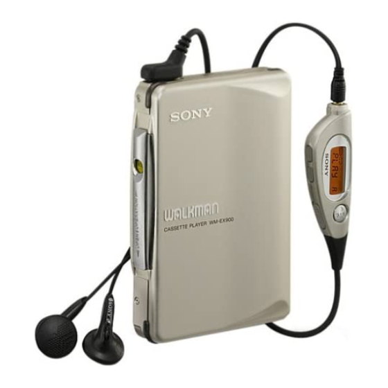
SECTION 2 GENERAL Location of controls • Main unit • Stereo headphones with remote control L (left) R (right) 1 VOL (volume) knob 2 2 REMOTE (headphone • remote control) jack 3 Operation button 4 OPEN/HOLD/OPERATION switch 5 Dry battery case contact 6 Rechargeable battery compartment 7 HOLD switch 8 Liquid crystal display window... -
Page 8: Disassembly
SECTION 3 DISASSEMBLY • The equipment can be removed using the following procedure. Cassette Lid Assy Case Ornament (OPEN) Sub Board, Leaf Switch, Belt (F1), Motor (F1) (M701) Block Assy Main Board Note : Follow the disassembly procedure in the numerical order given. 3-1. -
Page 9: Ornament (Open) Block Assy
3-3. ORNAMENT (OPEN) BLOCK ASSY 1 ornament (open) block assy mechanism deck block 3-4. SUB BOARD, LEAF SWITCH, MAIN BOARD 4 Unsolder the 6 places. 7 screw (M1.4) 1 screw !™ claw 8 leaf switch 9 Unsolder the plunger. 5 screw (M1.4) 6 SUB board 3 screw (M1.4x1.4) 0 Unsolder the... -
Page 10: Belt (F1), Motor (F1) (M701)
3-5. BELT (F1), MOTOR (F1) (M701) 1 belt (F1) 2 screws (M1.4) 4 motor (F1) (M701) 3 motor base (F1) – 8 –... -
Page 11: Mechanical Adjustments
SECTION 4 SECTION 5 MECHANICAL ADJUSTMENTS ELECTRICAL ADJUSTMENTS PRECAUTION PRECAUTION • Supplied voltage : 1.3 V 1. Clean the following parts with a denatured-alcohol-moistened • Switches and control position swab : playback head pinch roller VOL switch : NORM • Remote control position capstan rubber belt 2. -
Page 12: Diagrams
WM-EX9 SECTION 6 DIAGRAMS 6-1. BLOCK DIAGRAM HP701 (PLAYBACK) AUDIO AMP DOLBY AMP AUDIO AMP IC301 (1/2) FWD L IC302 IC301 (2/2) L CH PW IN L PRE OUT L J301 PW OUT L – FWD R – REMOTE R CH REV L REMO L CH... -
Page 13: Schematic Diagram
WM-EX9 6-3. SCHEMATIC DIAGRAM • Refer to page 19 for IC Block Diagrams. Note: • All capacitors are in µF unless otherwise noted. pF: µµF 50 WV or less are not indicated except for electrolytics and tantalums. • All resistors are in Ω and W or less unless otherwise specified. -
Page 14: Pin Description
6-4. IC PIN DESCRIPTION • IC701 ML63512-117 (SYSTEM CONTROL) Pin No. Pin Name Pin Description A/B SW Side A/B detection switch signal input. L: side A, H: side B FWD SW MD mode switch (FWD) signal input. L: ON CEN SW MD mode switch (CENTER) signal input. - Page 15 • IC Block Diagrams IC301 TA2123F 36 35 32 31 28 27 26 – CAMP SW RF IN MT TC PW GND – BEEP PW OUT R BEEP AMS OUT PW OUT C – NT SW PW OUT L PW SW BST SW TOMP F/R SW...
- Page 16 IC601 LB1994M M CENTER BUFFER COMPARATOR BUFFER P-SIG 13 PW COMPARATOR D/DT PULSE 12 CI POWER 11 Vref W OUT CURRENT V OUT U OUT SOFT CLIP 10 P SIG PW•SW CTRL BLOCK DECODER 4 5 6 IC704 S-80808ANNP-E7Y IC702 MM1305 OUT 1 Vref –...
-
Page 17: Exploded Views
SECTION 7 EXPLODED VIEWS NOTE: • The mechanical parts with no reference • -XX and -X mean standardized parts, so • Accessories and packing materials are number in the exploded views are not supplied. they may have some difference from the given in the last of this parts list. -
Page 18: Mechanism Deck Section
7-2. MECHANISM DECK SECTION (MT-WMEX9-162) PM701 M701 HP701 Ref. No. Part No. Description Remark Ref. No. Part No. Description Remark X-3376-293-1 HOLDER ASSY 3-029-283-01 GEAR, IDLER (A) X-3376-295-1 PINCH LEVER (R) ASSY 3-029-765-01 SCREW (M1.4), TOOTHED LOCK X-3376-294-1 PINCH LEVER (N) ASSY 3-029-268-01 FLYWHEEL (R), INSERT 3-029-275-01 WASHER (STOPPER N) 3-029-883-01 RETAINER BASE (F1), MOTOR... -
Page 19: Electrical Parts List
SECTION 8 MAIN ELECTRICAL PARTS LIST NOTE: • Due to standardization, replacements in • Items marked “*” are not stocked since The components identified by the parts list may be different from the they are seldom required for routine service. mark ! or dotted line with mark. - Page 20 MAIN Ref. No. Part No. Description Remark Ref. No. Part No. Description Remark IC703 8-759-553-28 IC XC6383C251ML R113 1-216-834-11 METAL CHIP 1/16W IC704 8-759-572-21 IC S-80808ANNP-E7Y-T2 R201 1-216-833-11 METAL CHIP 1/16W R202 1-216-837-11 METAL CHIP 1/16W < JACK > R203 1-216-789-11 METAL CHIP 1/16W R204...
- Page 21 MAIN Ref. No. Part No. Description Remark R711 1-218-892-11 RES, CHIP 0.50% 1/16W R712 1-218-907-11 RES, CHIP 330K 0.50% 1/16W R713 1-216-853-11 METAL CHIP 470K 1/16W R714 1-216-823-11 METAL CHIP 1.5K 1/16W R715 1-216-854-11 METAL CHIP 560K 1/16W R716 1-216-823-11 METAL CHIP 1.5K 1/16W R717...
- Page 22 WM-EX9 Sony Corporation 98K0470031-1 Printed in Singapore C1998. 11 9-924-980-11 Personal A&V Products Company Published by Quality Engineering Dept. – 26 – (Shibaura)