
Related Manuals for Toro VS-400


Summary of Contents for Toro VS-400
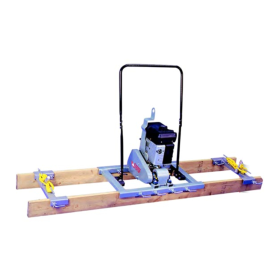
- Page 1 Form No. 3375-418 Rev B VS-400 and VS-800 Screed Model No. 68052—Serial No. 313000001 and Up Model No. 68053—Serial No. 313000001 and Up G020728 *3375-418* B Register at www.Toro.com. Original Instructions (EN)
-
Page 2: Introduction
Whenever you need service, genuine Toro parts, or additional WARNING information, contact an Authorized Service Dealer or Toro Customer Service and have the model and serial numbers of your product ready. Figure 1 identifies the location of the CALIFORNIA model and serial numbers on the product. Write the numbers Proposition 65 Warning in the space provided. -
Page 3: Table Of Contents
Contents Safety Introduction ..............2 Improper use or maintenance by the operator or owner Safety ................3 can result in injury. To reduce the potential for injury, Safe Operating Practices........... 3 comply with these safety instructions and always Safety and Instructional Decals ......... 5 pay attention to the safety alert symbol , which means: Caution , Warning , or Danger —personal safety... - Page 4 – Keep container nozzle in contact with the tank during filling. • Make any necessary repairs to the machine before starting. • Use only genuine Toro replacement parts to ensure that original standards are maintained.
-
Page 5: Safety And Instructional Decals
Safety and Instructional Decals Safety decals and instructions are easily visible to the operator and are located near any area of potential danger. Replace any decal that is damaged or lost. 125–8203 1. Read the Operator’s Manual for information on starting the 5. -
Page 6: Setup
Setup Installing the Tow Rope Installing the Handlebar Parts needed for this procedure: Left spreader Parts needed for this procedure: Right spreader Upper handlebar Pull grip Rope Bolt (5/16 x 1 inch) Nut (5/16 inch) Procedure Procedure 1. Thread the end of the rope through a pull grip (Figure Place the upper handlebar so that it can be installed using the nuts and bolts. -
Page 7: Installing The L-Bolts
Installing the L-bolts Checking the Oil Level Parts needed for this procedure: No Parts Required L-bolt Procedure Wingnut Before starting the engine for the first time, check the engine oil level; refer to Checking the Engine Oil Level (page 12). Assembling the L-bolts to the Machine and Spreaders 1. -
Page 8: Product Overview
Product Overview Controls Become familiar with all the engine controls before you start and operate the machine. Engine Controls G020816 Figure 6 1. Upper handlebar 7. Eccentric guard 2. Fuel tank 8. L-bolt 3. Air-filter housing 9. Wingnut 4. Lower handlebar 10. -
Page 9: Specifications
Choke Lever Engine On/Off Switch The choke lever (Figure 9) is required when starting a cold The On/Off switch (Figure 10) allows the operator of the engine. Before pulling on the recoil-start handle, move machine to start and stop the engine. This switch is located the choke lever to the closed position. -
Page 10: Operation
Operation Note: Determine the left and right sides of the machine Performance problems and/or engine damage may result from the normal operating position. which may not be covered under warranty. • Important: Before operating the machine, check the Do not use gasoline containing methanol. fuel and oil levels, and remove debris from the machine. - Page 11 Note: Fuel stabilizer/conditioner is most effective when DANGER mixed with fresh gasoline. To minimize the chance of varnish In certain conditions during fueling, static deposits in the fuel system, use fuel stabilizer at all times. electricity can be released causing a spark which can ignite the gasoline vapors.
-
Page 12: Checking The Engine Oil Level
-20 -10 0 20 30 40 C g013375 Figure 14 Note: Toro Premium Engine Oil is available from your Authorized Toro Dealer. 1. Place the machine on a flat, level surface, and stop the engine. 2. Allow the engine to cool. -
Page 13: Starting And Stopping The Engine
Starting and Stopping the Engine Starting the Engine 1. On the engine, move the throttle lever away from the Min position, 1/3 of the way toward the Max position (Figure 16); refer to Throttle Lever (page 9). G019747 Figure 17 Note: If the choke lever is set to the Closed position to start the engine, gradually move the choke lever back toward the Open position as the engine warms up. -
Page 14: Installing And Removing The Screed Boards
Installing and Removing the 5. Raise the rear of the machine 10 to 12 inches, and align the rear screed board to the rear U-channel of Screed Boards the frame (Figure 18). 6. Align the screed board to the U-channel, and center Note: Use straight 5 cm x 15 to 20 cm (2 inch x 6 to 8 inch) the board to the machine (Figure 18). -
Page 15: Screeding A Concrete Surface
Screeding a Concrete Surface 2. Start the engine; refer to Starting the Engine (page 13). 3. Move the throttle lever to the Fast position; refer to Throttle Lever (page 9). Leveling the Concrete Surface 4. Pull the screed in slow, steady motion along the This procedure levels a freshly poured concrete project to concrete forms (Figure 20). -
Page 16: Lifting The Machine
Lifting the Machine Moving the Machine with the Lifting Plate Important: Use lifting equipment with a 61 kg (134 lb) or greater lift capacity. 1. Remove the spreaders and screed boards from the machine; refer to Removing the Spreaders and Screed Boards (page 14). -
Page 17: Maintenance
Maintenance Note: Determine the left and right sides of the machine from the normal operating position. Recommended Maintenance Schedule(s) Maintenance Service Maintenance Procedure Interval • Inspect and adjust the belt. After the first 25 hours • Change the oil. After the first 50 hours •... -
Page 18: Premaintenance Procedures
CAUTION Disconnect the wires from the spark plugs before you do any maintenance. Set the wires aside so that they do not accidentally contact the spark plugs. Premaintenance Lubrication Procedures Greasing the Machine Preparing the Machine for Service Interval: Before each use or daily Maintenance Grease eccentric bearings every 8 operating hours and immediately after every washing. -
Page 19: Engine Maintenance
Engine Maintenance Note: Be careful to prevent dirt and debris from falling into the base. 5. Remove the foam and paper elements from the base Servicing the Air Cleaner (Figure 24). Service Interval: Before each use or daily—Inspect the air 6. -
Page 20: Changing The Engine Oil
5W 30 · 10W 30 100°F 40°C G019298 Figure 26 1. Oil viscosity range for ambient operating temperatures Toro Premium Engine Oil is available from your Authorized Toro Dealer. 1. Remove the oil cap/dipstick (Figure 27). G019297 Figure 25 1. Drain port 4. -
Page 21: Servicing The Spark Plug
Figure 28 1. Spark plug 2. Wire 4. Clean around the spark plug. 5. Rotate the spark plug counterclockwise using a 20 mm (13/16 inch) spark-plug wrench to remove the plug and sealing washer (Figure 29). G019746 Figure 27 1. Fill port 3. -
Page 22: Fuel System Maintenance
Fuel System Maintenance Servicing the Fuel System Cleaning the Sediment Cup Service Interval: Every 100 hours/Every 6 months G019300 (whichever comes first)—Clean the Figure 30 sediment cup. 1. Side electrode 3. Insulator Yearly or before storage—Clean the fuel sediment cup. 2. -
Page 23: Drive System Maintenance
Drive System 10. Move the lever of the fuel valve to the On position (all the way to the right) and check for leaks. If it leaks, Maintenance replace the O-ring. Lubricating the Clutch Service Interval: Monthly 1. From the back of the machine, locate the clutch cover that is between the lifting bracket and the belt (Figure 32). -
Page 24: Belt Maintenance
Belt Maintenance Removing and Installing the Belt Guard Removing the Belt Guard 1. At the back of the machine, locate the right-cross channel of the frame (Figure 33 and Figure 34). G020916 Note: The back of the machine is on the side opposite Figure 34 from the eccentric guard. -
Page 25: Servicing The Belt
Installing the Belt Guard 1. Align the belt guard over the pulleys. 2. Apply medium strength (service removable thread locking compound to the threads of the bolt (1/4 inch and 2 shoulder bolts (3/8 inch). 3. Align the (1/4 inch) hole in the belt guard with the hole in the belt guard bracket (Figure 34 and Figure 36). - Page 26 Installing the Belt 1. Align the belt over the clutch (Figure 37). 2. Pull the belt toward the eccentric pulley (Figure 36). 3. Slip the belt over the shoulder of the eccentric pulley (Figure 36). Note: Rotate the eccentric pulley by hand to help install the belt.
-
Page 27: Cleaning
Cleaning Storage Important: You can wash the machine with mild Cleaning the Machine detergent and water. Do not pressure wash the engine or eccentric bearings. Regular cleaning and washing will increase the life span of 1. Remove concrete, sand, and aggregate from the the machine. - Page 28 11. Store the machine unit in a clean, dry garage or storage area. 12. Cover the machine to protect it and keep it clean.
-
Page 29: Troubleshooting
Troubleshooting Problem Possible Cause Corrective Action The engine will not start. 1. The fuel-valve lever is in the Off 1. Move the fuel-valve lever to the On position. position. 2. The choke is closed. 2. Open the choke when starting a hot engine. - Page 30 Notes:...
- Page 31 Notes:...
- Page 32 Toro importer. If all other remedies fail, you may contact us at Toro Warranty Company. Australian Consumer Law: Australian customers will find details relating to the Australian Consumer Law either inside the box or at your local Toro Dealer.