Table of Contents
Advertisement
Quick Links
TABLE OF CONTENTS
1 Safety Precautions----------------------------------------------- 2
2 Specifications ----------------------------------------------------- 2
2.1. EY7451 MAIN UNIT -------------------------------------- 2
2.2. MAXIMUM RECOMMENDED CAPACITIES ------- 2
3 Troubleshooting Guide ----------------------------------------- 3
Troubleshooting Guide.) --------------------------------- 6
4 Disassembly and Assembly Instructions ---------------- 7
chuck.--------------------------------------------------------- 7
4.2. How to disassemble Main unit.------------------------- 8
5 Wiring Connection Diagram ---------------------------------13
6 Schematic Diagram ---------------------------------------------14
7 Exploded View and Replacement Parts List -----------15
7.1. PARTS LOCATION---------------------------------------15
7.2. REPLACEMENT PARTS LIST ------------------------16
Model No.
Europe
PAGE
© Panasonic Corporation 2018 Unauthorized copy-
ing and distribution is a violation of law.
Order Number PTD1808E01CE
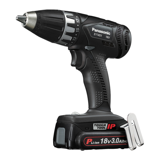
Cordless Drill & Driver
EY7451
Advertisement
Table of Contents
Troubleshooting

Related Manuals for Panasonic EY7451


Summary of Contents for Panasonic EY7451
-
Page 1: Table Of Contents
Europe TABLE OF CONTENTS PAGE 1 Safety Precautions----------------------------------------------- 2 2 Specifications ----------------------------------------------------- 2 2.1. EY7451 MAIN UNIT -------------------------------------- 2 2.2. MAXIMUM RECOMMENDED CAPACITIES ------- 2 3 Troubleshooting Guide ----------------------------------------- 3 3.1. Trial Operation (after checking Troubleshooting Guide.) --------------------------------- 6 4 Disassembly and Assembly Instructions ---------------- 7 4.1. -
Page 2: Safety Precautions
• Pb free solder will tend to splash when heated too high (about 1100°F / 600°C). 2 Specifications 2.1. EY7451 MAIN UNIT Motor 18V DC 70 ~ 400/min (rpm) No load speed... -
Page 3: Troubleshooting Guide
3 Troubleshooting Guide (Refer to Wiring Connection Diagram) -
Page 6: Trial Operation (After Checking Troubleshooting Guide.)
3.1. Trial Operation (after checking Troubleshooting Guide.) 3.1.1. ASSEMBLY 1. Confirm if there is NO gap between Housing A and B by pinching the lead wires. 2. Confirm all screws are tightened firmly. 3. There should be no abnormal sound when shaking the unit. 4. -
Page 7: Disassembly And Assembly Instructions
4 Disassembly and Assembly Instructions 4.1. How to disassemble Plate hoot and Keyless chuck. 4.1.1. Removal of the Housing. 4.1.2. Removal of Motor screw. Removal NOTE: 1. Loosen a screw. When attaching or removing a bit, disconnect battery pack 2. Take out the plate hook. from tool. -
Page 8: How To Disassemble Main Unit
4.2. How to disassemble Main unit. 4.2.1. Removal of the Housing. 4.2.3. Removal of Switch and Driving block. 1. Remove 8 housing screws. Removal 1. Take out the switch assembly. 2. Take out the driving block. 4.2.2. Removal of Motor screw. Removal 1. - Page 9 4.2.4. Removal or assembly of Control 4.2.5. Removal or attachment of the Gear PCB. Box Block. Removal Removal 1. Take out the connector from the control PCB. 1. Turn the thrust plate to remove. NOTE: 2. The internal parts of gear box block can be removed one Make sure hold the connector at the bottom area.
- Page 10 4.2.6. Assembly of the Adjusting Screw and the Clutch Handle. 1. Hold the driving block with the click spring on top, and 2. Turn the adjusting screw into the driving block about one align the narrow projection of adjusting screw with 45° rotation for clockwise direction.
- Page 11 4.2.7. Attachment of the H/L change han- dle. 1. Insert the both side of handle spring into the groove of Ring gear A.
- Page 12 4.2.8. Assemble of Driving block.
-
Page 13: Wiring Connection Diagram
5 Wiring Connection Diagram... -
Page 14: Schematic Diagram
6 Schematic Diagram... -
Page 15: Exploded View And Replacement Parts List
7 Exploded View and Replacement Parts List 7.1. PARTS LOCATION... -
Page 16: Replacement Parts List
7.2. REPLACEMENT PARTS LIST MODEL No.EY7451 Safety Ref. No. Part No. Part Name & Description Q'ty Remarks WEY7451K3078 HOUSING AB SET WEY6450L6808 CHUCK FASTENING SCREW WEY7441K7917 KEYLESS CHUCK WEY7441H3227 CLUTCH HANDLE WEY7441L0637 ADJUSTING SCREW WEY7441L0177 CLUTCH SPRING WEY7441L0577 CLUTCH PLATE...