
Related Manuals for Huawei ATOM GPS NE08E


Summary of Contents for Huawei ATOM GPS NE08E
- Page 1 ATOM GPS (Indoor NE08s and AE 905S) Quick Installation Guide Issue: 01 Date: 2016-12-20 HUAWEI TECHNOLOGIES CO., LTD.
-
Page 2: Trademarks And Permissions
Notice The purchased products, services and features are stipulated by the contract made between Huawei and the customer. All or part of the products, services and features described in this document may not be within the purchase scope or the usage scope. Unless otherwise specified in the contract, all statements, information, and recommendations in this document are provided "AS IS"... -
Page 3: Installation Flow
Installation Flow Start Page 1 Precautions Preparation Installation Page 1 Tools for Installation Introduction to the Page 2 ATOM GPS Page 3 Overall Installation Effect Pages Installing the GPS Satellite Antenna System Page 6 Perform power-on check Assembling OT Page 7 Terminals Pages Appendixes... -
Page 4: Tools For Installation
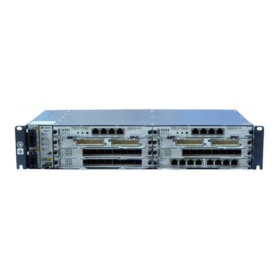
•When installing or maintaining fibers, do not look into the optical port without eye protection. The infrared laser emitted by the optical interfaces can cause permanent eye damage. NOTE Use cables delivered with Huawei devices or cables complying with Huawei standards. Tools for Installation Measuring tape... - Page 5 Introduction to the ATOM GPS Indoor NE08E (Example:NE08E-S6) Power supply interface Antistatic jack interface NM interface Clock interface (Console interface) Time interface Optical interface Alarm interface PGND point Electrical interface Optical interface AE 905S NOTE Before inserting an AE 905S to an optical interface, lock the ejector lever.
-
Page 6: Typical Scenario
Overall Installation Effect Typical Scenario 1 GPS antenna Feeder lightning protection component NE08E Route the feeder along the cable rack that is mounted on the wall and use feeder fasteners to fix the feeder. The interval between feeder fasteners is 2.5 m. Typical Scenario 2 GPS antenna Feeder... - Page 7 Installing the GPS Satellite Antenna System NOTE For requirements on the GPS installation, see GPS Satellite Antenna System Quick Installation Guide. For requirements on the GPS antenna position, see Appendixes 2. This document describes how to connect the ATOM GPS to the GPS. Deploy amplifiers based on the GPS feeder length.
- Page 8 Insert the AE 905S into an optical interface of Connect the other end of the coaxial cable to the NE08E device, with the wrench on the AE the AE 905S. 905S being locked. NOTE The coaxial cable must be routed without affecting the cabling of neighboring boards.
- Page 9 Perform power-on check Check the indicator of the AE 905S Status Description Steady on (Green) The AE 905S module works properly. the indicator Steady on (Red) The AE 905S module encounters a hardware fault or overtemperature event. Flashing at an interval of 1s The frequency or time of the GPS is out of (Red) lock.
- Page 10 Appendixes Assembling OT Terminals Material: OT terminals (ring terminals) , heat-shrinkable tube and cable. Press the end of the contact terminal on the Strip a part of the jacket off the cable to expose the conductor by using the crimping tool. conductor with a length of L1.
- Page 11 Requirements for GPS Antenna Installation Positions NOTE This describes the requirements for the installation positions of the GPS antennas under different installation environments. General Requirements 1.The GPS antenna should be installed in an open space and is far ≥ 90° from high buildings.