
Related Manuals for Siemens PAD-5 Series


Summary of Contents for Siemens PAD-5 Series
- Page 1 Model PAD-5 Intelligent Notification and Auxiliary Power Expander Installation Siemens Industry, Inc. A6V101030358_en--_c Smart Infrastructure...
- Page 2 Technical specifications and availability subject to change without notice. © 2020 Copyright by Siemens Industry, Inc. PAD-5 is a trademark of Siemens Industry, Inc. Transmittal, reproduction, dissemination and/or editing of this document as well as utilization of its contents and communication thereof to others without express authorization are prohibited.
- Page 3 In order to protect plants, systems, machines and networks against cyber threats, it is necessary to implement – and continuously maintain – a holistic, state-of-the-art security concept. Siemens’ portfolio only forms one element of such a concept. You are responsible for preventing unauthorized access to your plants, systems,...
-
Page 4: Table Of Contents
S600 Main Board RESET ................34 3.2.6.2 S601 Reset Status LED switch ..............34 3.2.6.3 S602 Ground Fault Supervision Switch ............34 Technical Data ....................34 Battery Size Calculations ................... 36 Battery Maintenance ..................38 Siemens Industry, Inc. A6V101030358_en--_c Smart Infrastructure... -
Page 5: Pad-5
(315-034686) for specifics about configuring the PAD-5-MB and its expansion modules. NOTE: Pathway Survivability: Each circuit must be evaluated and tested to ensure compliance to the application and area of protection to meet the criteria of NFPA 72. Siemens Industry, Inc. A6V101030358_en--_c Smart Infrastructure... -
Page 6: Properties
- Status LED indicates if output is in trouble, or was previously in trouble, in the case of an intermittent fault Integrated P2 loop circuitry for connection to Fire Panel device loop (P2) with isolation from short circuit capabilities. Siemens Industry, Inc. A6V101030358_en--_c Smart Infrastructure... - Page 7 NOTE 6: The battery charger is temperature compensated, to help increase the life of the batteries. Because very hot environments can shorten the life of batteries, the panel is set to disable the charger if the Siemens Industry, Inc. A6V101030358_en--_c Smart Infrastructure...
-
Page 8: Regulatory Standards
The PAD-5 meets the Class A requirements of the Code of Federal Regulations (CFR 47), Part 15, Subpart 15, for electromagnetic field emissions. General Specifications • Operating temperature 32 – 120ºF (0 – 49ºC) • Relative humidity Up to 93%RH @ 86ºF (30ºC) non-considering Siemens Industry, Inc. A6V101030358_en--_c Smart Infrastructure... -
Page 9: Installation
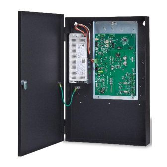
All field wiring and connections to the PAD-5-MB must be disconnected, and AC must be disconnected before removing fasteners and remov- ing the board assembly from the enclosure. Siemens Industry, Inc. A6V101030358_en--_c Smart Infrastructure... - Page 10 S54400-Z60-A1 (Document ID A6V10334250) 3. PAD-5-MB, P/N S54339-A5-A1 4. Max. Battery Size inside enclosure, 18AH Batteries, BP-61 P/N 175-387194 FP2012-U1 (300W) POWER SUPPLY FP2011-U1 (170W) ADAPTER PLATE POWER SUPPLY WITH PAD-5-MB Figure 3: Typical Configuration Siemens Industry, Inc. A6V101030358_en--_c Smart Infrastructure...
- Page 11 1. Enclosure, Model PAB2-ENCL-R, P/N S54339-A11-A1 (Red), or Model PAB2- ENCL, P/N S54339-A10-A1 (Black) 2. Power Supply, Model FP2011-U1, P/N 500-450222 or Model FP2012-U1, P/N S54400-Z60-A1 3. PAD-5-MB, P/N S54339-A5-A1 4. Max. Battery Size inside enclosure, up to 35AH Batteries, BTX1, P/N 175-083897 Siemens Industry, Inc. A6V101030358_en--_c Smart Infrastructure...
-
Page 12: Mounting The Boards
8. Before applying power, the address needs to be set on the PAD-5-MB (and the expansion card if using one). Do not have the expansion module connected to the Siemens Industry, Inc. A6V101030358_en--_c Smart Infrastructure... -
Page 13: Dpu Programming Pad-5-Mb And Expansion Card Address
3. The procedure for programming the cable can be found in the DPU manual (P/N 315-033260). DPU firmware Rev 09.01.0022 or greater is required in order to have compatibility with the PAD-5-MB and the expansion boards. Siemens Industry, Inc. A6V101030358_en--_c Smart Infrastructure... -
Page 14: Wire Routing
Figure 5a: PAD-5 Wire Routing in 1HU NOTE → If batteries larger than 18Ah are needed, an external battery box will be required. Route wires through Non-Power limited, knockout location A. Siemens Industry, Inc. A6V101030358_en--_c Smart Infrastructure... - Page 15 NOTE → If batteries larger than 35Ah are needed, an external battery box will be required. Route wires through Non-Power limited, knockout location A. Knockout Locations Non-Power Limited - High Voltage (AC power) Power Limited Power Limited Power Limited Power Limited Siemens Industry, Inc. A6V101030358_en--_c Smart Infrastructure...
-
Page 16: Wiring The Pad-5
IN PAD-5-ENCL (TO CONNECT GROUND WIRE FROM AC MAINS) CAUTION: INSTALL THE PROTECTIVE COVER ON THE AC MAINS (L, N, G) Figure 6: AC Wiring to FP2011-U1 (Doc P/N 315-050222) or FP2012-U1 (Doc ID A6V10334250) Siemens Industry, Inc. A6V101030358_en--_c Smart Infrastructure... -
Page 17: Wiring And Configuring The Pad-5-Mb
The diagram below is used to locate important parts of the board. X600 X700 X607 X606 H600 X602 X901 X701 X703 X900 S600 S602 H100 X100 S601 X101 H605 F100 X800 H500 H601 H501 X300 H602 H603 X400 H604 Figure 7: Component Location Siemens Industry, Inc. A6V101030358_en--_c Smart Infrastructure... - Page 18 X100 Connector for power supply (PS1) X101 Battery connection X300 NAC1,2 output X400 NAC3,4 output X600 NAC Follower Input X700 FDNet (P2) Input X800 Output DC 24 V AUX X900, X901 Expansion module connection Siemens Industry, Inc. A6V101030358_en--_c Smart Infrastructure...
-
Page 19: Wiring Power Supply And Battery To The Main Unit
AC IN ORANGE (PIN #1) 120/240V (+26VDC) 50/60Hz Figure 8: FP2012-U1 (Doc. ID A6V10334250) NOTE: Check brownout switch for the power supply and select proper source voltage. Figure 9: FP2011-U1 (Installation Instruction P/N 315-050222) Siemens Industry, Inc. A6V101030358_en--_c Smart Infrastructure... -
Page 20: Battery Compatibility
(Green) Power supply status indication. Used by the periphery board to know the health of the power supply. (Black) Return (ground) +24 V (Red) DC +24 V system supply Admissible cable cross-section: 1 x 12…18 AWG or 2 x 16…18 AWG Siemens Industry, Inc. A6V101030358_en--_c Smart Infrastructure... -
Page 21: X101 Battery Terminal
As soon as the temperature falls below the threshold, the batteries will continue to charge. The OI will post a trouble, and when the temperature is safe, the OI will post the “OUT”. Siemens Industry, Inc. A6V101030358_en--_c Smart Infrastructure... -
Page 22: Nac Circuits
ACTIVE. The dedicated Auxiliary Output (X800) will remain on, even if the battery charger is active. It is only NACs configured for Auxiliary Output that are affect by the battery charger priority. Siemens Industry, Inc. A6V101030358_en--_c Smart Infrastructure... -
Page 23: Wiring The Nac Circuits - Class B Nac1 And Nac2
* EOL resistor must be connected for NAC(s) not used. EOL resistance: 2.2K – 24K Ohms Combined Total output between all on-board NACs, Class A Expansion Module NACs, and AUX is 9A for a FP2012-U1 and 6A for a FP2011-U1 Siemens Industry, Inc. A6V101030358_en--_c Smart Infrastructure... - Page 24 Positive feed for notification appliances for NAC 2 Class A or NAC 4 Class B NAC4_- Return feed for notification appliances for NAC 2 Class A or NAC 4 Class B Admissible cable cross-section: 1 x 12…18 AWG or 2 x 16…18 AWG Siemens Industry, Inc. A6V101030358_en--_c Smart Infrastructure...
-
Page 25: Nacs (1-4) Configured As Auxiliary Circuits
Return feed for Contact Input Circuit 1 NAC2_+ Positive feed for Contact Input Circuit 2 NAC2_- Return feed for Contact Input Circuit 2 Admissible cable cross-section: 1 x 12-18 AWG or 2 x 16-18 AWG Siemens Industry, Inc. A6V101030358_en--_c Smart Infrastructure... -
Page 26: Nac Follower Input
(1, 2) and leave on (3, 4). If the PAD-5-MB is the end, then the EOL goes on (3, 4). If not, continue the run from (3, 4) to the next PAD-5-MB (1, 2). Siemens Industry, Inc. A6V101030358_en--_c Smart Infrastructure... - Page 27 Master NAC from PAD-5-MB Polarity shown in Active mode (or other NAC source) PAD-5 Last NAC Follower (configure in ZEUS as NAC follower) BF - X700 X600 Figure 11: Using NAC Follower with multiple XDLCs Siemens Industry, Inc. A6V101030358_en--_c Smart Infrastructure...
-
Page 28: X600 Nac Follower
X800 2 Combined Total output between all on-board NACs, Class A Expansion Module NACs, and AUX is 9A for a FP2012-U1 (300 Watt Power Supply) and 6A for a FP2011-U1 (170 Watt Power Supply). Siemens Industry, Inc. A6V101030358_en--_c Smart Infrastructure... -
Page 29: X800 Auxiliary Output Terminal Block
Designation Description Positive feed for FDNet (P2) IN / OUT Return feed for FDNet (P2) IN Return feed for FDNet (P2) OUT Admissible cable cross-section: 1 x 12-18 AWG or 2 x 16-18 AWG Siemens Industry, Inc. A6V101030358_en--_c Smart Infrastructure... -
Page 30: Topologies
NOTE: Class X wiring X700 X600 ONE SLOT OF CC -5 24V+ 24V- DO NOT USE TO 24 VDC FROM THE PSC -12 X DLC Card X700 PAD-5 PAD- 5 PAD-5 Figure 12: X700 Wiring Siemens Industry, Inc. A6V101030358_en--_c Smart Infrastructure... - Page 31 PAD-5 Device Device Device Device XDLC Siemens SLC Devices include polarity insensitive CLASS A Topology Dets, TRIs, Pull Stations, Call Points, Conventional Zone Modules, etc. (Mixed Mode – polarity insensitive and isolator devices) A maximum of 30 SLCs can be connected...
- Page 32 PAD-5 Device XDLC Device Device Siemens SLC Devices include polarity insensitive Dets, TRIs, Pull Stations, Call Points, Conventional Zone Modules, etc. CLASS B Topology All NACs provided by all PAD-5s on this circuit must serve a single notification zone. A...
-
Page 33: Led Indicators
Blinking for event message Blinking Indicates main microprocessor is processing data H600 Yellow P2 - Normal condition H700 Yellow P2 - Trouble Condition P2 – Pattern not Locatable? P2 – Pattern Locate? H701 Green Siemens Industry, Inc. A6V101030358_en--_c Smart Infrastructure... -
Page 34: Switches
FP2012-U1 (for batteries 35 Ah and larger) Rated: 9A Max @ 24 VDC Not power limited Battery output Plug strip X101 DC 20.4 V…DC 26.4 V Voltage (DC 24 V nominal) Current Max. 11.5 A Siemens Industry, Inc. A6V101030358_en--_c Smart Infrastructure... - Page 35 Current Max. 3 A ⚫ Design Short-circuit protection ⚫ Voltage surge protection ⚫ Power limited NAC follower input Plug strip X600 Voltage DC 24 V filtered Current Max. 12 mA Design Voltage surge protection Siemens Industry, Inc. A6V101030358_en--_c Smart Infrastructure...
-
Page 36: Battery Size Calculations
"Always ON" Note 3: AUX current must be included in the ALARM column if AUX circuit is configured as "Always ON" Note 4: For CDC ZONES, unused circuits should be selected as a shorting device. Siemens Industry, Inc. A6V101030358_en--_c Smart Infrastructure... - Page 37 For Releasing Application a battery rating of 18 Ah or greater is required, based on 24 hour Standby time and 5 minutes Alarm time (if greater than 18 Ah is needed, a PAB2- ENCL or external battery box will be needed). Siemens Industry, Inc. A6V101030358_en--_c Smart Infrastructure...
-
Page 38: Battery Maintenance
3. Load Voltage Test—With full system alarm load, the voltage on a fully charged battery must not fall below 24.6V after one minute. Testing Interval 1. Semiannually—Perform the Load Voltage Test. 2. Annually—Perform the Charger Test and Discharge Test. Siemens Industry, Inc. A6V101030358_en--_c Smart Infrastructure... - Page 39 Model PAD-5 Battery Size Calculations THIS PAGE HAS BEEN LEFT INTENTIONALLY BLANK. Siemens Industry, Inc. A6V101030358_en--_c Smart Infrastructure...
- Page 40 Issued by © 2020 Siemens Industry, Inc. Siemens Industry, Inc. Technical specifications and availability subject to change without notice. Smart Infrastructure 8 Fernwood Road Florham Park, NJ 07932 Tel. +1 973-593-2600 www.sbt.siemens.com/FIS Document ID A6V101030358_en--_c P/N A5Q00072307...