Table of Contents
Advertisement
Quick Links
Advertisement
Chapters
Table of Contents

Related Manuals for Siemens Dräger Medical Carina


Summary of Contents for Siemens Dräger Medical Carina
- Page 1 Instructions for Use Carina Sub-Acute Care Ventilator WARNING Software 3.n For a full understanding of the per- formance characteristics of this medical device, the user should carefully read these Instructions for Use before use of the medical device.
-
Page 2: Working With These Instructions For Use
Working with these Instructions for Use In the header – the subject of the main chapter To help you find your way around quickly. Operation On each page – the instructions for use Combining text with illustrations. The information is Setting ventilation modes Switching on, Carina shows the ventilation mode last set along with the set parameters. -
Page 3: Trademarks
Trademarks – AutoFlow ® – Carina ® – SyncPlus ® are registered trademarks of Dräger. – BIPAP* – Virex ® is a registred trademark of JohnsonDiversery. Definitions WARNING A WARNING statement provides important information about a potentially hazardous situation which, if not avoided, could result in death or serious injury. - Page 4 This page intentionally left blank Instructions for Use Carina SW 3.n...
-
Page 5: Table Of Contents
Contents Contents Working with these Instructions for Use ..2 Start-up....... 55 Trademarks . - Page 6 Contents Fault – Cause – Remedy ....95 PC-BIPAP ......132 PC-AC .
-
Page 7: Patients
For Your Safety and That of Your Patients For Your Safety and That of Your Patients Strictly follow these Instructions for Use ..8 Maintenance ......8 Accessories . -
Page 8: Strictly Follow These Instructions For Use
For Your Safety and That of Your Patients Strictly follow these Instructions for Use Safe connection with other electrical equipment WARNING WARNING Any use of the medical device requires full Electrical connections to equipment which is understanding and strict observation of all not listed in these Instructions for Use should portions of these instructions. -
Page 9: Functional Safety
For Your Safety and That of Your Patients Functional safety The essential performance consists in controlled and monitored patient ventilation with user-defined settings for the monitoring functions – minimum inspiratory breathing gas flow, – maximum airway pressure, or, if one of the limits set is exceeded, by an appro- priate alarm. -
Page 10: General Warnings And Cautions
For Your Safety and That of Your Patients General WARNINGS and CAUTIONS WARNING Do not use the device during magnetic reso- The following WARNINGS and CAUTIONS apply to nance (MRI, NMR, NMI)! Device operation may general operation of the device. WARNINGS and be affected, thus placing the patient at risk. -
Page 11: Note On Emc/Esd Risk For The Device
For Your Safety and That of Your Patients CAUTION WARNING Only use the device in well ventilated rooms to In the case of patients who require a high O prevent over heating of the device. concentration ensure that there is an emer- gency supply of oxygen available, e.g. -
Page 12: Back-Up Ventilation With An Independent Manual Ventilation Device
For Your Safety and That of Your Patients Back-up ventilation with an independent manual ventilation device WARNING If a fault is detected in Carina so that its life- support functions are no longer assured, ven- tilation using an independent ventilation device must be started without delay –... -
Page 13: Intended Use
Intended Use Intended Use Intended Use ......14 Sub-acute care definition ....14 Instructions for Use Carina SW 3.n... - Page 14 Intended Use Intended Use Carina – long-term ventilator for ventilator-depend- ent patients or ventilator-assisted patients. – For treatment of sub-acute care patients in hos- pital or medical rooms. – For invasive ventilation or non-invasive ventila- tion. – For patients with a tidal volume of at least 100 mL.
-
Page 15: System Overview
System Overview System Overview Main functions ......16 Ventilation modes ......16 Supplements. -
Page 16: Main Functions
System Overview Main functions Ventilation modes Ramp Variable rise in pressure from the lower pressure VC-SIMV AF level to the upper pressure level. Volume Control – Synchronized Intermittent Man- datory Ventilation – AutoFlow Intermittent triggered mechanical ventilation (vol- Volume Guarantee ume-controlled) in conjunction with spontaneous VG ensures that patients receive a defined tidal vol- breathing. -
Page 17: Gas Supply
System Overview The following are displayed as a bar graph: To protect the patient and the user against electrical – Airway pressure hazards, it is essential that all systems consisting of medical devices as well as other electrical devices Display of: which are not restricted to computers, printers etc., –... -
Page 18: Control Panel, Top
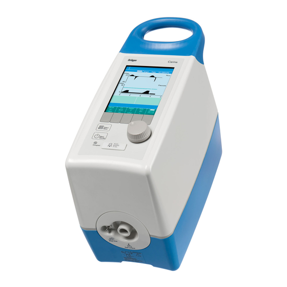
System Overview Control panel, top 1 Carrying handle 2 Screen for application-specific information on ventilation 3 Buttons for selecting functions and ventilation parameters 4 Centre rotary knob for setting and confirming functions and parameters 5 »Audio paused 2 min.« button for suppressing the alarm tone for 2 minutes and for visual indication of alarm status: red = warning, yellow = caution... -
Page 19: Front Connection Block
System Overview Front connection block 1 Ventilation hose connection 2 Emergency air inlet and oxygen overflow 3 Connection for control hose (for hose system with expiratory valve) Rear connection block 4 Not assigned 5 Connection for nurse call system 4 5 6 7 6 RS 232 serial port for data communication (MEDIBUS) 7 Not assigned... -
Page 20: Trolley 1-63 Cm, Trolley 1-78 Cm
System Overview Trolley 1-63 cm, Trolley 1-78 cm 1 Carina bracket 2 Standard rail grip 3 Universal bracket with standard rail, optional 4 Trolley column 5 Pedastal 6 Red locking lever of the column mount closed (under pedestal) 7 Dual rollers with locking brakes, 4 each 8 Battery holder, optional Instructions for Use Carina SW 3.n... -
Page 21: Symbols
System Overview Symbols Mains switch ON Menu 1 Menu 2 Mains switch OFF Menu 3 Connection for nurse call system Observe the Instructions for Use! Data port Gas inlet (emergency air inlet) Power supply display Gas outlet (oxygen overflow) Standby mode ON/OFF Disposal information Turn off audible alarm Connection for control hose... -
Page 22: Abbreviations
System Overview Abbreviations Abbreviation Explanation Abbreviation Explanation Apn. Vent. Apnoea ventilation Leakage minute volume leak AutoFlow Automatic optimisation of inspi- Non-invasive ventilation ration flow (mask ventilation) Breaths per minute Pascal, unit of pressure Ventilation strokes per minute 1 mbar = 100 Pa = 1 hPa 1 bar = 100 kPa = 1000 hPa BTPS Body Temperature, Pressure,... - Page 23 System Overview Abbreviation Explanation Delay time for »Airway pressure disconn low !!!« alarm Expiration time Inspiration time setting Ti max Maximum inspiration time setting Tube Tube ventilation (invasive ventilation) UMDNS Universal Medical Device Nomenclature System Nomenclature for medical devices VC-SIMV Volume Control –...
- Page 24 This page intentionally left blank Instructions for Use Carina SW 3.n...
-
Page 25: Operating Concept
Operating concept Operating concept Control panel ......26 Centre rotary knob ..... . . 26 Buttons with a fixed function. -
Page 26: Control Panel
Operating concept Control panel Centre rotary knob 1 For setting and confirming functions and venti- lation parameters. To set the value, turn rotary knob. To confirm, press rotary knob. Buttons with a fixed function 2 »Audio paused 2 min.« button for switching off the alarm tone for 2 minutes. -
Page 27: Screen
Operating concept Screen Layout 1 Alarm line for indicating audible alarm switched off and alarm message 2 Status line for current device settings 3 Display for real-time waveforms of flow and pressure or bar display for pressure and 4 measured values 4 Display for 2 measured values, configurable 5 Information line, e.g. -
Page 28: Setting Ventilation Mode
Operating concept Display of relevant ventilation parameters 1 When setting a ventilation parameter the rele- vant ventilation values calculated by Carina are indicated in the display field for »Value 1«. When the setting has been confirmed, the dis- play field closes. Colour concept Yellow Function/parameter selected, not... -
Page 29: Calling Up Menus
Operating concept Calling up menus 1 Press »Select Menu« button. All the menus are shown. 2 Press the button for the relevant menu. The functions and parameters of the menu selected are displayed, e.g. »Vent.Set« menu. Expanding menus 3 In the case of menus with more than 4 or 8 func- tions/parameters the other functions/parame- ters can be activated by pressing the button. - Page 30 This page intentionally left blank Instructions for Use Carina SW 3.n...
-
Page 31: Preparation
Preparation Preparation Information on preparation ....32 Connecting to the nurse call system..52 Fitting the inlet filter ..... 32 MEDIBUS interface . -
Page 32: Information On Preparation
Preparation Information on preparation Before every use, reprocess Carina and all the accessories according to the information in the Instructions for Use, see page 103. Comply with the hospital's hygiene regulations! Fitting the inlet filter Unpack the inlet filter. 1 Insert the inlet filter at the bottom, 2 swivel it in and 3 press at the top until its snaps into place. -
Page 33: Carina With Trolley
Preparation Stability To prevent the device from tipping over, only use Carina up to a maximum inclination of 15°! Carina with trolley Use Dräger trolley "Trolley 1-63 cm" or "Trolley 1-78 cm" only. Before use, check readiness for operation of the trolley: 1 Red locking lever of the column mount closed, 2 Attachments such as standard rail grip or... -
Page 34: Position Carina On The Trolley
Preparation Position Carina on the trolley Open both locks. WARNING Only touch the grip part of the locks. Risk of trapping fingers at the lock! 1 Red areas must be visible. Hold Carina with both hands and place the holes in the underside of the device over the mounting pins. -
Page 35: Attach Universal Bracket With Standard Rail
Preparation Attach universal bracket with standard rail Attach right side of holder to right side of column. 1 Make sure the nose of the universal bracket is completely behind the revolving edge. 2 Attach the left side of the holder to the left side of the column. -
Page 36: Attaching Battery Holder
Preparation Attaching battery holder 1 Press the locks inwards to open. 2 Open the door of the battery holder. Position the battery holder against the column. Attach the battery holder. Use the four provided bolts. Tighten the four bolts. Use the provided Allen key. -
Page 37: Use In The Hospital
Preparation Use in the hospital WARNING For greater stability, move accessories into their optimal position for moving the trolley: Move hinged arm to its smallest extension. Keep hoses as close to the trolley as pos- sible. Hang the humidifier on the trolley, do not attach to the device! Otherwise there is a risk of falling. - Page 38 Preparation Moving the trolley 1 Release all four locking brakes. 2 Hold and move the trolley by gripping the stand- ard rail or the trolley column. Parking the trolley 3 Engage all four locking brakes. Instructions for Use Carina SW 3.n...
-
Page 39: Information On Using Bacterial Filters, Hme Systems And Hose Systems
Preparation Information on using bacterial filters, HME systems and hose systems Any additional components in the breathing system Therefore: and any components that do not belong to the The condition of the patient and the ventilator's standard hose system can substantially increase measured values for air volume must be inspiratory and expiratory breathing resistance checked more frequently. -
Page 40: Connecting A Hose System
Preparation Connecting a hose system WARNING Make sure that the selected hose system cor- responds to the device setting! Carina might not give an alarm when using an incorrect hose system. In such cases, meas- ured volumes can differ significantly from the actual volumes! WARNING Do not use antistatic or conductive hoses. -
Page 41: Hose System With Leak Valve
Preparation Hose system with leak valve 1 Open the sliding cover on the underside of Carina. 2 Using a coin, turn the switch to leak valve » « until it is properly engaged. 3 Close the sliding cover. CAUTION Switching between a hose system with leak valve and a hose system with expiratory valve must be carried out by properly trained personnel only! Risk of malfunction! -
Page 42: Attaching The Hinged Arm
Preparation 4 Connect the filter to socket » «. 5 Connect the ventilation hose to the filter. 6 Connect the expiratory valve to the nozzle of the ventilation hose. When using the disposable hose system VENTSTAR Carina ExpV (MP 00 313) the expiratory valve is included. -
Page 43: Connecting A Respiratory Gas Humidifier
Preparation Connecting a respiratory gas humidifier WARNING Install a water trap when using a respiratory gas humidifier. Otherwise the flow inside of the hoses can be blocked by condensed water. WARNING Place the device and the respiratory gas humidifier on a stable, firm surface. Otherwise the humidifier might fall. -
Page 44: Respiratory Gas Humidifier Without
Preparation Respiratory gas humidifier without inspiratory heater For hose system with leak valve Turn the switch to leak valve » «, see page 41. 1 Connect the filter to socket » «. 2 Connect ventilation hoses, observing hose 60 cm lengths! 60 cm 3 Place the water trap vertically at the lowest... -
Page 45: Heater
Preparation Respiratory gas humidifier with inspiratory heater For hose system with leak valve Turn the switch to leak valve » «, see page 41. 1 Connect the filter to socket » «. 2 Fit the ventilation hoses according to the instructions for the respiratory gas humidifier, observing hose lengths. -
Page 46: Preparing The Aeroneb Pro Nebuliser
Preparation Preparing the Aeroneb Pro nebuliser WARNING During medication nebulisation do not use a heat and moisture exchanger (HME). Risk of increased breathing resistance. WARNING Do not nebulise flammable medication, fire hazard! Position the nebuliser near to the patient. Observe the Instructions for Use of the neb- uliser being used! Instructions for Use Carina SW 3.n... -
Page 47: Connecting To The Power Supply
Preparation Connecting to the power supply CAUTION Maintain a sufficiently charged external battery on hand, in the possible event of a power supply failure. NOTE Route hoses safely to reduce the risk of tripping. A stationery device can be supplied either from the mains or from an external battery. -
Page 48: External Battery Connection
Preparation External battery connection 1 Insert the DC connector in the Carina. 2 Connect the external battery. Refer to the Instructions for Use of the external battery. External battery The external battery is not charged from the Carina mains supply! External battery for 3rd party connection 12 to 24 V DC (–10 % to +30 %);... -
Page 49: Internal Battery
Preparation Internal battery If the external power supply (mains/external bat- tery) should fail, Carina automatically switches over to supply from the internal battery. If the battery is fully charged, ventilation can be per- formed reliably for approx. 60 minutes without any external power supply (assuming average ventila- tion parameters and normal ambient conditions). -
Page 50: O 2 Supply, Connect
Preparation supply, connect WARNING WARNING Keep oil and grease away from all oxygen sup- Make sure there is adequate ventilation at the ply components. Risk of explosion due to rear of Carina. Do not use an O source which spontaneous combustion! supplies a flow in excess of 10 L/min. -
Page 51: Hpo - High Pressure Oxygen Mode
Preparation HPO – High Pressure Oxygen mode For O supply to Carina from the central gas supply or from a O gas cylinder. WARNING compressed gas must be dust-free, oil-free and dry and its pressure should be between 2.7 and 6 bar (270 and 600 kPa). Risk of fire. WARNING Only use O gas supplies with 100 % O... -
Page 52: Connecting To The Nurse Call System
Preparation Connecting to the nurse call system Socket on the back of Carina to transmit alarms to a central alarm system within the clinic. WARNING A nurse call system used in conjunction with Carina must conform to IEC 60601-1-8 and transmit alarms from Carina within 5 seconds. -
Page 53: Medibus Interface
Preparation MEDIBUS interface CAUTION The data port (data transfer) may only be con- nected by EDP (Electronic Data Processing) staff trained in maintenance and repair. Use Dräger "Babylink Cable" 83 06 488. Insert the plug into the » « socket on the rear of Carina and screw tight. - Page 54 This page intentionally left blank Instructions for Use Carina SW 3.n...
-
Page 55: Start-Up
Start-up Start-up Information on start-up ....56 Switching on Carina ..... 56 Checking readiness for operation . -
Page 56: Information On Start-Up
Start-up Information on start-up Before starting up for the first time and after any lengthy period of storage always charge the inter- nal battery of Carina for at least 2 hours. CAUTION The Carina shall not be operated immediately fol- lowing storage or transport outside the recom- mended operating conditions. -
Page 57: Checking Readiness For Operation
Start-up The self test is followed by the screen showing the ventilation mode and parameters last set. The device is in standby mode. Checking readiness for operation This test must be conducted every time before the device is put into operation. The checklist on page 58 can be copied for docu- mentation purposes. -
Page 58: Checklist
Start-up Checklist Action Observe Check Connect all necessary equipment: hoses, Equipment is connected correctly, refer to cable, filter, etc. page 31. Turn the main switch on. Carina performs a self-test, LEDs light up and alarm tone is given. Check if the used hose system (leak valve or »LeakV«... -
Page 59: Selecting An Application Method
Start-up Switching Carina to Standby Press »Start/Standby« button and confirm with rotary knob. Carina is in standby mode. LED in the button flashes. The screen displays »Standby – Patient not ventilated«. Selecting an application method In the configuration menu set the method to »Mask«... -
Page 60: Setting The O 2 Supply
Start-up Setting the O supply Carina has been set to HPO mode by the manufac- turer. For LPO mode, configure LPO, see page 78. Dräger recommends the use of an external oxygen monitor add to the patient circuit to measure the actual oxygen concentration. -
Page 61: Operation
Operation Operation Setting ventilation modes ....62 Chart for operation with leak valve (MP 00 312)......79 Calling up the ventilation settings menu . -
Page 62: Setting Ventilation Modes
Operation Setting ventilation modes Switching on, Carina shows the ventilation mode last set along with the set parameters. Calling up the ventilation settings menu 1 Press »Select Menu« button. 2 Press the »Vent.Set« button and the ventilation mode last set is indicated. Changing the ventilation mode 3 Press button for the ventilation mode. -
Page 63: Setting Ventilation Parameters
Operation Setting ventilation parameters 1 Press button for the ventilation parameter required. Select the value using the rotary knob and con- firm. Values set on delivery Ventilation mode PC-AC 500 mL 15 mbar insp PEEP 3 mbar 40 % 15 bpm 1.3 s Ti max Δ... -
Page 64: Vc-Simv Af
Operation VC-SIMV AF Volume Control – Synchronized Intermittent Man- datory Ventilation AutoFlow Volume-controlled ventilation with fixed mandatory Ramp high Ramp low minute volume MV, set with tidal volume VT and frequency f. Between the mandatory ventilation PEEP strokes the patient can breathe spontaneously. AutoFlow –... -
Page 65: Setting Ranges
Operation Setting ranges Ventilation parameter Setting range Tidal volume VT [mL] 100 to 2000 PEEP [mbar] 3 to 20 Inspiratory O concentration FiO 21 to 100 Trigger sensitivity Trigger Off/Normal/Sensitive Frequency f [bpm] 5 to 50 Inspiration time Ti [sec] 0.3 to 8 or I:E 1:39 to 2:1... -
Page 66: Pc-Bipap
Operation PC-BIPAP Pressure Control – Biphasic Positive Airway Pressure Pressure-controlled ventilation in conjunction with Ramp high Ramp low free spontaneous breathing during the entire Pinsp breathing cycle. The mandatory portion of total PEEP minute volume MV is adjusted with inspiration pres- sure P , PEEP and frequency f. -
Page 67: Setting Ranges
Operation Setting ranges Ventilation parameter Setting range Inspiration pressure P [mbar] LeakV: 5 to 40 insp ExpV: 5 to 50 PEEP [mbar] 3 to 20 Inspiratory O concentration FiO 21 to 100 Trigger sensitivity Trigger Off/Normal/Sensitive Frequency f [bpm] 5 to 50 Inspiration time Ti [sec] 0.3 to 8 or I:E... -
Page 68: Pc-Ac
Operation PC-AC Pressure Control – Assist Control Pressure-controlled, assisted ventilation Ramp high Ramp low Every inspiratory effort of the patient on PEEP level Pinsp triggers a synchronized mandatory breath. PEEP Trigger window Flow with spontaneous without spontane- breathing ous breathing Set PC-AC with the buttons for the ventilation parameters: –... -
Page 69: Setting Ranges
Operation Setting ranges Ventilation parameter Setting range Inspiration pressure P [mbar] LeakV: 5 to 40 insp ExpV: 5 to 50 PEEP [mbar] 3 to 20 Inspiratory O concentration FiO 21 to 100 Trigger sensitivity Trigger Off/Normal/Sensitive Frequency f [bpm] 5 to 50 Inspiration time Ti [sec] 0.3 to 8 or I:E... -
Page 70: Spn-Ps
Operation SPN-PS Spontaneous Pressure Support For patients with sufficient spontaneous breathing. Spontaneous breathing at an increased pressure level to raise the functional residual capacity. Spon- taneous breathing can be supported with Pressure Support. Set SPN-PS with the buttons for the ventilation parameters: –... -
Page 71: Setting Ranges
Operation Setting ranges Ventilation parameter Setting range Pressure support Δ P [mbar] LeakV: 2 to 40 (with PEEP) supp ExpV: 2 to 50 (with PEEP) PEEP [mbar] 3 to 20 Inspiratory O concentration FiO 21 to 100 Trigger sensitivity Trigger Normal/Sensitive Maximum inspiration time Ti max [sec] 0.4 to 10.0... -
Page 72: Spn-Cpap
Operation SPN-CPAP Spontaneous Continuous Positive Airway Pressure Suitable for patients with sufficient spontaneous breathing. Spontaneous breathing at an increased pressure level to raise the functional residual capacity. Set CPAP with the buttons for the ventilation parameters: – Positive end expiratory pressure »CPAP« –... -
Page 73: Apnoea Ventilation
Operation Apnoea ventilation For automatically switching to volume-controlled, Start of apnoea Ventilation Spontaneous mandatory ventilation (VC-SIMV) in the event of breathing with apnoea. pressure support Can be switched on in ventilation modes SPN-PS PEEP and SPN-CPAP. The device gives an alarm »Apnoea ventila- tion!!!«... -
Page 74: Volume Guarantee
Operation Volume guarantee Can be switched on in ventilation mode SPN-PS. Tidal volume guarantee Inspiratory plateau pressure is automatically regu- lated between P and PEEP in such a way that the set tidal volume VT is applied. Set volume guarantee with the parameters: –... -
Page 75: Niv - Non-Invasive Ventilation
Operation NIV – Non-invasive Ventilation WARNING An intubated patient must not be ventilated in Mask ventilation is only possible in combination »Mask« mode! with a hose system with leak valve. A leakage may lead to a temporary change of Using mask ventilation the delivered volume to the patient. -
Page 76: Selecting The "Mask" Application Method
Operation In the »Mask« application method all the ventilation modes are available for selection. Selecting the »Mask« application method Switch Carina to standby mode. Press »Select Menu« button. Press »Config.« button. Press » « button. Press »Method« button. Select and confirm »Mask« with rotary knob. The status line shows »Mask«. -
Page 77: Lpo - Low Pressure Oxygen Mode
Operation LPO – Low Pressure Oxygen mode NOTE WARNING If O is simultaneously supplied from the central Only connect O sources which meet the fol- gas supply or a gas cylinder and from the O con- lowing conditions: centrator, LPO supply is prevented. flow: 10 L/min max. -
Page 78: Setting Lpo Mode
Operation Setting LPO mode Switch Carina to standby mode. Press »Select Menu« button. Press »Config.« button. Press » « button. Press »LPO« button. Select and confirm »On« with rotary knob. The status line on the screen shows »LPO«. Setting O concentration Set oxygen flow at the flow control valve in accordance with medical prescription:... -
Page 79: Chart For Operation With Expiratory Valve
Operation Chart for operation with expiratory valve (MP 00 313) as a function of minute volume and LPO flow Minute volume in L/min Chart for operation with leak valve (MP 00 312) as a function of P and LPO flow mean Mean airway pressure in mbar Instructions for Use Carina SW 3.n... -
Page 80: Locking Buttons
Operation Displaying set values and measured values Measured values, set values and pressure curve are displayed. 1 Press »Select Menu« button. 2 Press »Values« button (only available during operation). The screen displays: – Settings – Measured values – graphic representation of Paw NOTE Measured Frequency on VC-SIMV and PC-BIPAP displays only mandatory breaths per... -
Page 81: Terminating Ventilation
Operation Terminating ventilation Press the »Start/Standby« button and confirm with rotary knob. Carina has terminated ventila- tion and is in standby mode. LED in the button flashes. The screen shows »Standby – Patient not ventilated«. Switching off the device Switch Carina to standby. 1 Set the mains switch to »... -
Page 82: Improve Displayed Accuracy Of The Charging Capacity Of The Internal Battery
Operation Improve displayed accuracy of the charging capacity of the internal battery NOTE If charging and discharging cycles are incom- plete, the charging capacity of the internal battery may be displayed inaccurately. If the internal indication accuracy is not reliable enough the following message will appear: »Battery indication not reliable !«... -
Page 83: Monitoring
Monitoring Monitoring Setting alarm limits ..... 84 In the event of an alarm ....85 More than one alarm at the same time. -
Page 84: Setting Alarm Limits
Monitoring Setting alarm limits 1 Press »Select Menu« button. 2 Press »Alarms« button. Carina displays the alarm limits set. = Upper alarm limit = Lower alarm limit The current measured value is displayed between the upper and lower alarm limits. To set: Press the appropriate button. -
Page 85: In The Event Of An Alarm
Monitoring Extreme settings Certain ventilation parameters are limited by Carina to a threshold value. Extreme values can only be set after confirmation by pressing the rotary knob. In the event of an alarm If the alarm message, e.g. »MV high !!«, appears in the alarm line on the screen. -
Page 86: Troubleshooting
Monitoring More than one alarm at the same time If more than one alarm occurs at the same time, the alarm with the higher priority is displayed. When the cause has been remedied, the alarm with the lower priority is displayed. Troubleshooting Use the "Fault –... -
Page 87: Configuration
Configuration Configuration Carina Configuration ....88 Calling up the »Config.« menu ....88 Service menu . -
Page 88: Carina Configuration
Configuration Carina Configuration The following settings for application can be made under »Config.«: – Volume and type of alarm tone – Language, date and time – Screen display of curves and measured values – LPO mode on/off – Selection of mask or tube ventilation –... -
Page 89: Service Menu
Configuration The configuration menu shows the configurable functions and parameters: – Service for system and contact information and log book – Volume – adjustable from 1 to 5 – Tone – default tone or Dräger tone can be selected – Screen – adjustable for displaying curves or val- –... -
Page 90: Displaying System Information
Configuration Carina displays the functions of the Service menu: – System Information – for displaying device data and for setting system time and the current lan- guage – Contact – for displaying contact information for the customer – Log book – for displaying technical alarm mes- sages Displaying system information Press »Syst.info«... -
Page 91: Setting Volume Of The Alarm Tone
Configuration Setting the language The language can be changed only on standby set- ting. On the »system information« screen, select the »current language« line by rotating the knob and confirming. The language is high- lighted. Set the appropriate language using the rotary knob and confirm. -
Page 92: Selecting Screen Display
Configuration Select Dräger tone or the default tone and con- firm. The tone selected is displayed. Selecting screen display The screen display can be set: 1 Press »Screen« button. Select »Curves« or »Measure« and confirm. The current setting is displayed in the button. 2 Pressure curve as a bar chart, 4 measured val- ues and 2 configurable measured values. -
Page 93: Selecting Display For 2 Measured Values
Configuration Selecting display for 2 measured values Value 1 and value 2 are freely selectable for the dis- play. 1 Value 1: Off, PIP, VTi (VT), f, PEEP, MVi (MV), leak mean 2 Value 2: Off, PIP, VTi (VT), f, PEEP, MVi (MV), leak mean The measurements for value 1 and value 2 cannot... -
Page 94: Selecting Ti Or I:e
Configuration Selecting Ti or I:E Set I:E (time ratio of inspiration to expiration) or inspiration time Ti. 1 Press »Ti / I:E« button. Select »Ti« or »I:E« and confirm. Setting the night screen If the device is set to »Night« screen and it is not operated for 3 minutes or no alarm has occurred, the screen switches off. -
Page 95: Fault - Cause - Remedy
Fault – Cause – Remedy Fault – Cause – Remedy Fault – Cause – Remedy ....96 Displaying technical alarm causes ..101 Rescue Ventilation . -
Page 96: Fault - Cause - Remedy
Fault – Cause – Remedy Fault – Cause – Remedy Carina displays alarm messages in hierarchical order in the alarm line on the screen. If two faults are detected at the same time, the more critical fault is displayed. The priority of alarm messages is indicated by dif- ferent background colours and with exclamation marks after the message: !!! =... - Page 97 Fault – Cause – Remedy Error message Cause Remedy Battery indication not reliable Battery indication is not relia- Proceed the action on page 82. ble. If the problem persists call DrägerService. Blower overheated The blower has overheated. Make sure air is being supplied (in log book »Blower over- The device is operating at to the device.
- Page 98 Fault – Cause – Remedy Error message Cause Remedy External power failure The device has no external Check the mains supply or DC power supply. power supply. The mains plug or DC plug is Insert the mains plug or DC loose.
- Page 99 Fault – Cause – Remedy Error message Cause Remedy Int. battery low Battery charge has dropped to Charge the battery: connect below 25 %. external power supply. Int. battery low Battery charge has dropped to Charge the battery: connect below 50 %. external power supply.
- Page 100 Fault – Cause – Remedy Error message Cause Remedy MV high The minute volume has Check condition of patient, exceeded the upper alarm check ventilation pattern, cor- limit. rect alarm limit if necessary. Leakage in breathing system. Ensure that breathing system is leak-proof.
-
Page 101: Displaying Technical Alarm Causes
Fault – Cause – Remedy Error message Cause Remedy Standby activated The device is ready for opera- To start ventilation: press the tion. Ventilation is in standby »Start/Standby« button. mode. Technical alarm The device has a technical Use a replacement device. (in log book problem. - Page 102 This page intentionally left blank Instructions for Use Carina SW 3.n...
-
Page 103: Cleaning, Disinfection And Sterilisation
Cleaning, Disinfection and Sterilisation Cleaning, Disinfection and Sterilisation General information on cleaning, disinfection and sterilisation... . . 104 Care list ......105 Dismantling the components . -
Page 104: General Information On Cleaning, Disinfection And Sterilisation
Cleaning, Disinfection and Sterilisation General information on cleaning, disinfection and sterilisation WARNING In case of potential contamination with body fluids, clean and disinfect the device. Wear protective clothing, goggles, disposable gloves etc. Risk of infection for hospital staff and other patients. WARNING Personnel should take precautions to avoid direct contact with chemical disinfectants and... -
Page 105: Care List
Cleaning, Disinfection and Sterilisation Care list What How often Cleanable components Recommended cleaning intervals Carina basic device per patient Dismantle, clean and if applicable wipe disinfect Trolley per patient Dismantle, clean and if applicable wipe Compressed gas hose disinfect Hinged arm Reusable ventilation hoses per patient/weekly Dismantle, clean and disinfect in the... -
Page 106: Cleaning
Cleaning, Disinfection and Sterilisation Cleaning Wipe disinfection with Virex Tb Wipe surfaces with a clean, damp lint-free cloth. This procedure is applicable for Virex Tb. When Do not use corrosive detergents. using Virex Tb or other disinfectants strictly follow the disinfectant manufacturer's instructions. Aged or accumulated deposits should not be Clean the surfaces according to the cleaning scraped off, but should instead be softened with... -
Page 107: Maintenance
Maintenance Maintenance Maintenance intervals ....108 Replacing the inlet filter....109 Taking the device out of operation for a lengthy period . -
Page 108: Maintenance Intervals
Maintenance Maintenance intervals Clean and disinfect equipment and/or compo- nents before any maintenance procedures and before returning for repair. Inlet filter (HEPA filter) Replace after 6 months or in accordance with hospital-specific regulations, page 109. For disposal see page 112. NiMH battery To be replaced by technicians after 3 years. -
Page 109: Replacing The Inlet Filter
Maintenance Replacing the inlet filter WARNING Do not operate the device without an inlet fil- ter: risk of infection! When the inlet filter is removed the »Inlet filter missing !!« alarm is displayed. 1 Unlock the inlet filter, fold it down and remove it from the holder. -
Page 110: Visual Inspection Of Accessories
Maintenance Maintenance of the internal battery The battery has no memory effect. If the battery is not used regularly it discharges. Charge at regular intervals depending on ambient temperature: Every 3 months for –20 to +35 °C Every month for +35 to +55 °C Charge the battery more frequently at higher tem- peratures. -
Page 111: Disposal
Disposal Disposal Disposing of the internal battery ..112 Disposing of the inlet filter ....112 Disposing of the device ....112 Instructions for Use Carina SW 3.n... -
Page 112: Disposing Of The Internal Battery
Disposal Disposing of the internal battery Do not throw onto a fire, risk of explosion! Do not open by force, risk of acid burns! NiMH batteries are special waste: dispose according to relevant national waste disposal regulations. For information consult your environment agency, local government offices or appropriate waste dis- posal companies. -
Page 113: Technical Data
Technical Data Technical Data Ambient conditions ....114 Settings ......114 Performance data . -
Page 114: Ambient Conditions
Technical Data Ambient conditions During operation Temperature +5 to +35 °C Atmospheric pressure 900 to 1100 hPa reduced functionality at 700 to 900 hPa Rel. humidity 5 to 95 % non-condensing In storage and transportation Temperature (up to 1 day) –20 to +60 °C Temperature (up to 1 month) –20 to +55 °C... -
Page 115: Performance Data
Technical Data Inspiration time Ti 0.3 to 8 seconds Resolution 0.1 second Inspiration/expiration ratio I:E 1:39 to 2:1 Ramp rise time Ramp Auto (device uses the measured breathing rate to calculate the optimum value) 0.1 to 2.0 seconds Resolution 0.1 second Trigger sensitivity Trigger Off, Normal, Sensitive Apnoea ventilation Apn. -
Page 116: Monitoring
Technical Data Inspiratory tidal volume VTi, Range 0 to 4000 mL, BTPS Resolution 1 mL Accuracy ±10 % of the measured value (without leakages) Waveform display Airway pressure Pressure (t) 0 to 80 mbar Flow (t) –160 to +160 L/min Bar graph display Airway pressure Pressure 0 to 60 mbar... -
Page 117: Operating Data
Technical Data Operating data Power supply Mains 100 to 240 V AC (–20 to +10 %); 50 to 60 Hz; 1.7 to 1.1 A Internal battery Charging capacity 2.5 Ah Type NiMH Charging time 130 minutes Operating time 60 minutes (at average ventilation parameters and normal ambient conditions) Remaining operating time 3 minutes (time between loss of all power and generating of... -
Page 118: Classification
Technical Data Screen TFT color screen 13.7 cm (5.4 inch) Classification Classification in accordance with Direc- tive 93/42/EEC Appendix IX Protection class II, acc. to IEC 60601-1 Connection block Type BF Electromagnetic compatibility EMC tested according to IEC 60601-1-2: 2001 UMDNS code 14-355 Universal Medical Device Nomenclature... -
Page 119: Hose Systems
Technical Data Hose systems Ambient conditions Temperature during operation 10 to 40 °C Temperature during storage –20 to 60 °C Atmospheric pressure 500 to 1100 hPa Rel. humidity 5 to 95 % non-condensing Performance Data Resistance at 60 L/min <2 mbar Compliance <1.5 mL/mbar Leakage... -
Page 120: Emc Declaration
Technical Data EMC Declaration General information The EMC conformity of Carina includes the use of the following external cables and accessories: Description Order-No. DC-cable S, 1.75 m 84 14 048 Cable mains Euro CL II, 2.5 m 57 30 042 Power cable Switzerland, 18 51 691 3 m, 10 A... -
Page 121: Electromagnetic Emissions
Technical Data Electromagnetic emissions Carina is intended for use in the electromagnetic environment specified below. The customer or the user of the Carina should assure that it is used in such an environment. Emissions Compliance according to Electromagnetic environment Radio frequency emission Group 1 Carina uses RF energy only for its (CISPR 11) - Page 122 Technical Data Immunity against IEC 60601-1-2 Compliance Electromagnetic environment test level level (of Carina) Power frequency mag- 3 A/m 3 A/m Power frequency magnetic fields netic field (50/60 Hz) should be at levels characteristic of a (IEC 61000-4-8) typical location in a typical commercial or hospital environment.
-
Page 123: Recommended Separation Distances
Technical Data Recommended separation distances Recommended separation distances between port- able and mobile RF-telecommunication devices and the Carina. Max. P 3 V/m distance 1 V/m distance (m) Examples EIRP 0.001 0.06 0.17 0.003 0.10 0.30 0.010 0.18 0.55 0.030 0.32 0.95 e.g. - Page 124 This page intentionally left blank Instructions for Use Carina SW 3.n...
-
Page 125: Description
Description Description Mode of operation ..... 126 Functional units ......126 Adding oxygen HPO . -
Page 126: Mode Of Operation
Description Mode of operation pilot line for exp. valve Inlet Outlet Motor labyrinth labyrinth blower Patient (e.g. Silent Flow) Sensor Δp board Δp control DPS1 board DPS3 Functional units 1 Air inlet 2 Blower 3 Measuring unit 4 Expiratory valve 5 Leak valve 6 Oxygen metering unit 7 Oxygen measuring unit... -
Page 127: Adding Oxygen Hpo
Description The measured values of the first pressure sensor proportional valve (V5). Adding to the respiratory (PS1) and the second pressure sensor (PS2) are air takes place in the blower (2). used to regulate ventilation pressure. The calcula- tion incorporates the following: set values, ventila- Adding oxygen LPO tion algorithms and characteristic of the original The switchover to low-pressure oxygen is per-... -
Page 128: Losses
Description Compensation of volume and pressure losses Carina with hose system with leak valve compen- sates leakages from valve and patient. However, to compensate the volume loss due to the compliance of the different hose systems, con- sider the following table: ΔP above Hose system Volume loss... -
Page 129: Vc-Simv
Description VC-SIMV Volume Control – Synchronised Intermittent Man- Unsynchronised datory Ventilation Synchronised manda- mandatory tory ventilation stroke ventilation stroke Hybrid form of mandatory ventilation and spontane- ous breathing. Ramp Ramp SIMV enables the patient to breathe spontaneously in regular prescribed cycles, with the mechanical PEEP mandatory ventilation strokes providing a minimum Trigger-... -
Page 130: Autoflow
Description In the course of progressively weaning the patient from artificial ventilation, the ventilation frequency f is further reduced while the spontaneous breathing time is increased, so that the required total minute volume is supplied more and more by spontaneous breathing. -
Page 131: Patient-Oriented Settings
Description If the patient breathes in or out during mandatory inspiration, inspiration pressure PIP does not change for that ventilation stroke – only inspiration flow and expiration flow adapt to patient demand. The individually administered tidal volume VT may differ from set tidal volume VT in single ventilation PEEP strokes but the tidal volume VT administered on average over time, is constant. -
Page 132: Pc-Bipap
Description PC-BIPAP Pressure Control – Biphasic Positive Airway Pressure This PC-BIPAP ventilation mode is pressure-con- Ramp high Ramp low trolled or time-controlled ventilation during which Pinsp the patient can always breathe spontaneously. PEEP PC-BIPAP is thus often described as a time-control- led change between two pressure levels. -
Page 133: Pc-Ac
Description The display of calculated tidal volume VT is used to set the necessary difference between the two pres- sure levels. As in VC-SIMV, the time pattern is set with the parameters of the basic setting for frequency f and inspiration time Ti. -
Page 134: Spn-Ps
Description SPN-PS Spontaneous Pressure Support For pressure support of insufficient spontaneous breathing. The function of the device in supporting insufficient Δ P spontaneous breathing is similar to that of the supp above anaesthetist who manually assists and monitors PEEP the patient's spontaneous breathing by feeling the Ramp breathing bag. -
Page 135: Spn-Cpap
Description SPN-CPAP Spontaneous Continuous Positive Airway Pressure Spontaneous breathing at a raised pressure level in CPAP order to increase the functional residual capacity (FRC). Flow Tube (Invasive ventilation) The Carina is used to provide invasive ventilation to the appropriate patients. The following guidelines should be considered prior to use. -
Page 136: Mask Ventilation (Non-Invasive Ventilation)
Description Using invasive ventilation with VentStar Carina ExpV (MP 00 313) This hose system has an expiratory valve. There- fore the exhaled gas runs through the expiratory valve instead of the inspiratory limb when the device is not operating. Mask ventilation (Non-invasive ventilation) NIV (the mask ventilation) WARNING... -
Page 137: Information Concerning Co 2 Re-Breathing
Description Information concerning CO re-breathing WARNING In general, as inspiratory time increases, the WARNING potential for CO re-breathing increases. A Never leave the mask on patient while Carina higher inspiratory time decreases exhalation is not ventilating. There is a risk of CO time, allowing less CO to be purged from the breathing in case of no ventilation. -
Page 138: Syncplus
Description SyncPlus Volume Guarantee (VG) SyncPlus is an automatic function for supporting The ventilation mode extension VG allows for the NIV (mask ventilation). volume support on SPN-PS mode. Carina controls This automatic technology are supported by 3 main inspiratory plateau pressure automatically, in order features: to deliver the set tidal volume. -
Page 139: Volume Measurement
Description Volume measurement The gas volume that did not flow back through the sensor must have escaped through the leak. VTi (hose system with leak valve) Volume accuracy in case of leakages VTi value displayed on the screen is the volume of Due to Carina's limited monitoring functionality (no air delivered to the patient’s lungs (not in internal monitoring of expiratory minute volume),... -
Page 140: Autoramp
Description AutoRamp Ramp setting has 2 options – Time setting: The steepness of the pressure rise from the PEEP level to the inspiration pres- sure level can be even more closely adapted to the needs of the patient in all ventilation mode except CPAP. -
Page 141: Index
Index Index connecting ......40 with expiratory valve ....41 Abbreviations . - Page 142 Index Rear ........19 Respiratory gas humidifier ....43 with inspiratory heater .
- Page 143 This page intentionally left blank Instructions for Use Carina SW 3.n...
- Page 144 These Instructions for Use only apply to Carina SW 3.n with the Serial No.: If no Serial No. has been filled in by Dräger, these Instructions for Use are provided for general information only and are not intended for use with any specific machine or device.