Table of Contents
Advertisement
Quick Links
Advertisement
Table of Contents

Related Manuals for Motorola SE955


Summary of Contents for Motorola SE955
- Page 1 SE955 INTEGRATION GUIDE...
- Page 3 SE955 INTEGRATION GUIDE 72E-72322-13 Revision A May 2011...
- Page 4 Motorola. No right to copy a licensed program in whole or in part is granted, except as permitted under copyright law. The user shall not modify, merge, or incorporate any form or portion of a licensed program with other program material, create a derivative work from a licensed program, or use a licensed program in a network without written permission from Motorola.
- Page 5 -05 Rev A 3/2007 Correct custom defaults information -06 Rev A 3/2008 Motorola rebranding, add specular reflection information, add window properties information, update CUSTOM_DEFAULTS SSI command, add UPC/EAN supplemental options and Bookland ISBN Format parameter -07 Rev A 2/2009 Add Disable All Code Types and User Parameter Pass Through features...
- Page 6 SE955 Integration Guide...
-
Page 7: Table Of Contents
Introduction ............................ 2-1 Grounding ..........................2-1 ESD ............................2-1 Environment ..........................2-1 Mounting ............................2-2 Installing the SE955 ........................2-3 Optical ............................2-4 Housing Design ........................2-4 Wavefront Distortion ........................ 2-5 Collection Beam Geometry ...................... 2-5 Laser Clear Aperture ........................ 2-6 Collection Clear Aperture ...................... - Page 8 Scan Engine Developer Kit ...................... 2-19 Regulatory Requirements ......................2-19 Chapter 3: Replacing Existing Engines Introduction ............................ 3-1 Replacing an SE824 with the SE955 Scan Engine ............... 3-1 Mounting ..........................3-1 Electrical ..........................3-2 Optical ............................3-2 Mechanical ..........................3-2 Regulatory ..........................
- Page 9 Table of Contents Chapter 6: Regulatory Requirements Introduction ............................ 6-1 Required Documentation for Class 1 Laser Products ..............6-1 Required Documentation for Class 2 Laser Products ..............6-2 Required Documentation for all End Products ................6-2 Required Labeling for Class 1 End Products ................. 6-3 1 - Certification Statement from FDA/IEC Label Set, 2005 ............
- Page 10 SE955 Integration Guide Enable/Disable UPC-E ......................8-19 Enable/Disable UPC-E1 ......................8-20 Enable/Disable EAN-8 ......................8-20 Enable/Disable EAN-13 ......................8-21 Enable/Disable Bookland EAN ....................8-21 Decode UPC/EAN Supplementals ................... 8-22 User-Programmable Supplementals ..................8-26 Decode UPC/EAN Supplemental Redundancy ............... 8-26 Transmit UPC-A Check Digit ....................
- Page 11 Table of Contents Chinese 2 of 5 ..........................8-53 Enable/Disable Chinese 2 of 5 ....................8-53 Codabar ............................8-53 Enable/Disable Codabar ......................8-53 Set Lengths for Codabar ......................8-54 CLSI Editing ..........................8-55 NOTIS Editing .......................... 8-55 MSI ..............................8-56 Enable/Disable MSI .........................
- Page 12 SE955 Integration Guide ATTRIBUTE_SET ........................9-19 ATTRIBUTE_STORE ....................... 9-20 Remote Monitoring Commands ..................... 9-21 Time to Decode ........................9-21 Internal Temperature ....................... 9-21 Motor Frequency ........................9-22 Part Number ..........................9-22 Serial Number .......................... 9-23 Date of Manufacture ........................ 9-23 Date of Last Service .........................
- Page 13 Table of Contents Appendix B: Miscellaneous Code Information Introduction ............................ B-1 GS1-128 (formerly UCC/EAN-128) ....................B-1 AIM Code Identifiers ........................B-3 Setting Code Lengths Via Serial Commands ................B-6 Setting Prefixes and Suffixes Via Serial Commands ..............B-7 Index Tell Us What You Think...
- Page 14 SE955 Integration Guide...
-
Page 15: About This Guide
ABOUT THIS GUIDE Introduction The SE955 Integration Guide provides general instructions for mounting and setting up the SE955-I100R, SE955-I300R, SE955-E100R, SE955-I105R, and 955-E105R scan engines as well as instruction for replacing an existing SE824, SE923, or SE1223WA scan engine with an SE955. -
Page 16: Notational Conventions
• Chapter 10, Simple Serial Interface describes the system requirements of the Simple Serial Interface (SSI), which provides a communications link between Motorola decoders and a serial host. • Appendix A, Serial Interface Specification describes the requirements for digital systems to exchange asynchronous serial data, and provides transaction examples. -
Page 17: Service Information
Software type and version number Motorola responds to calls by e-mail, telephone or fax within the time limits set forth in service agreements. If your problem cannot be solved by Motorola Solutions support, you may need to return your equipment for servicing and will be given specific directions. - Page 18 SE955 Integration Guide...
-
Page 19: Chapter 1 Getting Started
• RoHS compliant upon product release. The SE955 delivers a new level of performance in miniature scan engines and sets your product apart from the competition. With over 8 million scan engines installed worldwide, Motorola scan engines are unmatched for... -
Page 20: Theory Of Operation
SE955 Integration Guide Theory of Operation The SE955 is a scan engine combined with a microprocessor to control the functionality of the engine, perform software decoding of the bar code information and provide a communication link to the host computer. -
Page 21: Microprocessor
Remote Scanner Management (RSM). For example, through SSI commands, the host can poll the SE955 for a measurement of temperature, as measured by circuitry on the PCB. For a full listing of the information that is available, see... -
Page 22: Simple Serial Interface (Ssi)
1-3) is asserted. The host uses this signal to remove power from the SE955. Do not remove power without using this signal since the PWRDWN signal is the only indication if the decoder is not transmitting, receiving, decoding, or writing data to... - Page 23 The SE955 enters Sleep power state only once, as soon as possible. Note: All wake up signals (see Table 1-2) must be inactive to enter Sleep power state. Once the SE955 is awakened, at least 1 second must elapse before it re-enters Low Power mode. Waking Up the SE955...
-
Page 24: Electrical Interface
Electrical Interface Table 1-3 lists the pin functions of the SE955 interface and illustrates typical input and output circuitry for the SE955-I100R, SE955-I300R, SE955-E100R, SE955-I105R and SE955-E105R. The SE955-I100R/I300R/E100R accepts a 3.3 VDC +/- 10% power input, designated as V . - Page 25 Getting Started 1 - 7 Input/Output Characteristics Table 1-4 Input Characteristics Output Characteristics SE955-I100R/I300R/E100R SE955-I100R/I300R/E100R Conditions *0.2 0.4 V BATT OL = 0.8mA *0.8 - 0.5 BATT BATT OH = -0.2mA - 1.0 BATT OH = -1.0mA DLED*/BPR* 1 mA...
-
Page 26: Beeper Definitions
1 - 8 SE955 Integration Guide Beeper Definitions The SE955 issues different beep sequences and patterns to indicate status. Table 1-5 defines beep sequences that occur during both normal scanning and while programming the scan engine. Beeper Definitions Table 1-5... -
Page 27: Chapter 2 Installation
Grounding CAUTION The SE955 chassis is connected to GROUND. If you are installing the SE955 to a hot or powered host, you must isolate the two. The best integration practice is to avoid ground loops wherever possible. There is a potential for creating a ground loop by grounding the SE955 chassis to the ground of the system in which the SE955 is being integrated. -
Page 28: Mounting
There are two mounting holes (M1.6 x 0.35), and two locator holes on the bottom of the chassis (see Figure 2-1). The SE955 can be mounted in any orientation with no degradation in performance. Top View (SE955-I100R/I300R/E100R) Top View (SE955-I105R/E105R) -
Page 29: Installing The Se955
Do not place magnetic material (e.g., dynamic speakers, ringers, vibrators, inductors, metal parts) within 1 inch of the SE955 chassis. The SE955 scan element used to generate the scan line has a magnet on one end. Locating magnetic or ferrous material near the scan engine may influence the pointing of the scan line emitted from the engine. -
Page 30: Optical
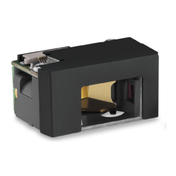
SE955 Integration Guide Optical The SE955 uses a sophisticated optical system that provides scanning performance that matches or exceeds the performance of much larger scan engines. The performance of the scan engine is not affected by a properly designed enclosure. -
Page 31: Wavefront Distortion
Installation 2 - 5 Wavefront Distortion Wavefront distortion is a measure of the window’s optical quality. Since the optical requirements of the exit window are different for the exit and entrance beam envelopes, a laser clear aperture and the collection clear aperture are defined. -
Page 32: Laser Clear Aperture
2 - 6 SE955 Integration Guide Laser Clear Aperture The laser clear aperture is the area on the exit window that intersects the exit beam envelope as shown in Figure 2-3. Note that at any instance in time, the outgoing laser beam is collimated and approximately 1 mm in diameter, while during scanner operation the beam is constrained within the exit beam envelope. -
Page 33: Exit Window Materials
Installation 2 - 7 Exit Window Materials Many window materials that look perfectly clear to the eye can contain stresses and distortions which affect the laser beam and reduce scan engine performance. For this reason, only optical glass or cell cast plastics are recommended. -
Page 34: Abrasion Resistance
2 - 8 SE955 Integration Guide Abrasion Resistance To gauge a window’s durability, quantify its abrasion resistance using ASTM standard D1044, Standard Test Method for Resistance of Transparent Plastics to Surface Abrasion. Also known as the Taber Test, this measurement quantifies abrasion resistance as a percent increase in haze after a specified number of cycles and load. - Page 35 Installation 2 - 9 Exit Window Manufacturers and Coaters Table 2-4 Company Discipline Specifics Evaporated Coatings, Inc. Anti-reflection coater Acrylic window supplier 2365 Maryland Road Anti-reflection coater Willow Grove, PA 19090 (215) 659-3080 Fosta-Tek Optics, Inc. Cell-caster, hard coater, laser cutter CR39 exit window manufacturer 320 Hamilton Street Leominster, MA 01453...
-
Page 36: Location And Positioning
2 - 10 SE955 Integration Guide Location and Positioning NOTE Integrate the scan engine in an environment no more extreme than the product’s specification, where the engine does not exceed its temperature range. For instance, do not mount the engine on to or next to a large heat source. -
Page 37: Symbol Position With Respect To A Fixed-Mount Scan Engine
Symbol Position with Respect to a Fixed-Mount Scan Engine It is sometimes necessary to mount the SE955 in such a way that it is able to read symbols that are automatically presented to it, or that are always presented in a pre-determined location. In these situations positioning of the SE955 with respect to the symbol location is critical. -
Page 38: Exit Window Characteristics
2 - 12 SE955 Integration Guide Exit Window Characteristics Exit Window Tilt Angle Figure 2-6 Exit Window Distance from Scan Engine: 0.15 in - 0.36 in (3.8 mm - 9 mm) Table 2-5 Distance from Scan 0.15/ 0.156/ 0.18/ 0.20/ 0.22/... - Page 39 “Direct Field of View of Photo Detector.” 6.The SE955 scan engine does not require margin on either side of the bar code to decode.The 47° scan line provides identical scanning performance to older scan engines with a scan line of 53°.
- Page 40 2 - 14 SE955 Integration Guide Exit Window Distance from Scan Engine: 0.15 in - 0.36 in (3.8 mm - 9 mm) Table 2-7 Distance from Scan 0.15/ 0.156/ 0.18/ 0.20/ 0.22/ 0.24/ 0.25/ 0.26/ 0.28/ 0.31/ 0.36/ Engine on center line 6.35...
-
Page 41: Accessories
Installation 2 - 15 Accessories Flex Cables A flex strip cable can be used to connect the SE955 scan engine to OEM equipment. Figure 2-8 illustrates the 12-pin tapered flex strip cable (p/n 15-81378-01), Figure 2-9 illustrates the 12-pin 53 mm even width flex strip... -
Page 42: Hardware Accessories
2 - 16 SE955 Integration Guide Hardware Accessories Table 2-11 lists sources for hardware accessories for the scan engine. Hardware Accessories Table 2-11 Company Discipline Specifics Tower Fasteners Inc. Fasteners Metallic, non-magnetic M1.6 x 0.35 machine screws. Length is integration dependent. However, a minimum 1690 North Ocean Ave. - Page 43 Installation 2 - 17 Tapered 12-Pin Flex Strip The 12-pin to 12-pin flex strip (p/n 15-81378-01), may be used only for evaluation purposes and not for production units (see Figure 2-8) Flex Strip, p/n 15-81378-01 (Tapered) Figure 2-8...
- Page 44 2 - 18 SE955 Integration Guide 0.2 ± 0.04 0.2 ± 0.04 5.00 ± 1.00 5.00 ± 1.00 2.09 ± 0.20 53.00 ± 5.00 0.02 ± 0.01 0.50 ± 0.05 0.26 ± 0.01 0.22 ± 0.01 0.011 6.50 ± 0.10 5.50 ±...
-
Page 45: Scan Engine Developer Kit
The Scan Engine Developer Kit (p/n DKSE-1000-000R) enables development of products and systems around the SE955 using the Windows 98, 2000, or XP platform. The kit provides the software and hardware tools required to design and test the embedded scan engine application before integration into the host device. - Page 46 2 - 20 SE955 Integration Guide...
-
Page 47: Chapter 3 Replacing Existing Engines
SE824 and SE955 scan engines. The SE955 can be used as a replacement for the SE824 scan engine, however, the mounting holes for the SE955 do not match those of the SE824. You must modify the mounting holes and locating pins on the host device. -
Page 48: Electrical
The SE824 scan engine operates at a Vcc of 3.3 VDC (±10%) and the SE955-I100R/I300R/E100R scan engines operate at a Vcc of 3.0 VDC to 3.6 VDC. The SE955-I105R/E105R scan engines operate at a Vcc of 3.2 VDC to 5.5 VDC. -
Page 49: Regulatory
Replacing an SE923 with the SE955 Scan Engine The SE955 can be used as a replacement for the SE923 scan engine. The mounting holes for the SE955 match those of the SE923. The SE923 scan engine chassis is electrically connected to Vcc while the SE955 scan engine chassis is electrically connected to ground and must be isolated from the host Vcc and ground. -
Page 50: Electrical
The SE923 scan engine operates at a Vcc of 3.3 to 5.0 VDC (±10%). The SE955-I100R/I300R/E100R scan engines operate at a Vcc of 3.0 VDC to 3.6 VDC. The SE955-I105R/E105R scan engines operate at a Vcc of 3.2 VDC to 5.5 VDC. -
Page 51: Regulatory
The SE955 can be used as a replacement for the SE1223WA scan engine. However, the mounting holes for the SE955 do not match those of the SE1223WA. In order to mount the SE955 in place of an SE1223WA, use adapter bracket, KT-1200MB-01, to mount the SE955. -
Page 52: Electrical
The SE1223WA scan engine operates at a Vcc of 5.0 VDC (±10%). The SE955-I100R/I300R/E100R scan engines operate at a Vcc of 3.0 VDC to 3.6 VDC. The SE955-I105R/E105R scan engines operate at a Vcc of 3.2 VDC to 5.5 VDC. -
Page 53: Mechanical
Replacing Existing Engines 3 - 7 Mechanical When replacing an SE1223WA scan engine with the SE955 scan engine the following must be taken into consideration: • Regulatory labels must reflect new VLD power. • Consider that existing cable flexes may not be compatible with the SE955 scan engine. - Page 54 3 - 8 SE955 Integration Guide...
-
Page 55: Chapter 4 Se955-I100R/I300R/E100R Specifications
CHAPTER 4 SE955-I100R/I300R/E100R SPECIFICATIONS Introduction This chapter provides the technical specifications of the SE955-I100R, SE955-I300R, and SE955-E100R scan engines. Decode zone and exit window characteristics are also presented. Technical Specifications Technical Specifications @ 23°C Table 4-1 Item Description Power Requirements Input Voltage 3.0 VDC to 3.6 VDC... - Page 56 47° ± 3° Narrow 35° ± 3° Note: The SE955 scan engine does not require margin on either side of the bar code to decode.The 47° scan line provides identical scanning performance to older scan engines with a scan line of 53°.
- Page 57 Technical Specifications @ 23°C (Continued) Table 4-1 Item Description Laser Safety SE955-I100R/I300R: IEC60825-1 Class 2 SE955-E100R: IEC60825-1 Class 1 Operating Temperature (chassis) -4° F to 140° F (-20° C to 60° C) Storage Temperature -40°F to 158° F (-40° C to 70° C)
- Page 58 4 - 4 SE955 Integration Guide Skew Pitch ± 65° from normal Pitch Angle Skew Angle ± 50° from normal Scan Beam Scan Beam Roll ± 35° from ± 35° from vertical Roll Angle Scan Beam Pitch, Skew and Roll...
-
Page 59: Decode Zones
SE955-I100R/I300R/E100R Specifications 4 - 5 Decode Zones The decode zones for the SE955-I100R/I300R scan engines are shown in Figure 4-2 Figure 4-3. The decode zones for the SE955-E100R scan engines are shown in Figure 4-4 through Figure 4-5. The figures shown are typical values. - Page 60 4 - 6 SE955 Integration Guide SE955-I100R/I300R Standard Version 47° Decode Zone Figure 4-3...
- Page 61 SE955-I100R/I300R/E100R Specifications 4 - 7 SE955-I100R/I300R Decode Distances Table 4-2 Symbol 35 ° Typical 35 ° Guaranteed 47 ° Typical 47 ° Guaranteed Density/ Working Ranges Working Ranges Working Ranges Working Ranges Bar Code Code Content/ Note 1 Type/ Contrast...
- Page 62 4 - 8 SE955 Integration Guide SE955-E100R Standard Version 35° Decode Zone Figure 4-4...
- Page 63 SE955-I100R/I300R/E100R Specifications 4 - 9 SE955-E100R Standard Version 47° Decode Zone Figure 4-5...
- Page 64 4 - 10 SE955 Integration Guide SE955-E100R Decode Distances Table 4-3 Symbol 35 ° Typical 35 ° Guaranteed 47 ° Typical 47 ° Guaranteed Density/ Bar Code Working Working Working Working Bar Code Content/ Ranges Ranges Ranges Ranges Note 1...
-
Page 65: Chapter 5: Se955-I105R/E105R Specifications
CHAPTER 5 SE955-I105R/E105R SPECIFICATIONS Introduction This chapter provides the technical specifications and decode zones for the SE955-I105R and SE955-E105R scan engines. Technical Specifications Technical Specifications @ 23°C Table 5-1 Item Description Power Requirements Input Voltage 3.2 VDC - 5.5 VDC Scanning Current 90 mA typical / 105 mA max. - Page 66 47° ± 3° Narrow 35° ± 3° Note: The SE955 scan engine does not require margin on either side of the bar code to decode.The 47° scan line provides identical scanning performance to older scan engines with a scan line of 53°.
- Page 67 5 - 3 Technical Specifications @ 23°C (Continued) Table 5-1 Item Description Laser Safety SE955-I105R: IEC60825-1 Class 2 SE955-E105R: IEC60825-1 Class 1 Operating Temperature -4° F to 140° F (-20° C to 60° C) (chassis) Storage Temperature -40°F to 158° F (-40° C to 70° C)
- Page 68 5 - 4 SE955 Integration Guide Skew Pitch Pitch Angle Skew Angle ± 50° from normal ± 65° from normal Scan Beam Scan Beam Roll Roll ± 35° from vertical Angle Scan Beam Pitch, Skew and Roll Figure 5-1...
-
Page 69: Decode Zones
SE955-I105R/E105R Specifications 5 - 5 Decode Zones The decode zones for the SE955-I105R scan engine are shown in Figure 5-2 through Figure 5-3. The decode zones for the SE955-E105R scan engine are shown in Figure 5-4 through Figure 5-5. The figures shown are typical values. - Page 70 5 - 6 SE955 Integration Guide SE955-I105R Standard Version 47° Decode Zone Figure 5-3...
- Page 71 SE955-I105R/E105R Specifications 5 - 7 SE955-I105R Decode Distances Table 5-2 Symbol 35 ° Typical 35 ° Guaranteed 47 ° Typical 47 ° Guaranteed Density/ Bar Code Working Ranges Working Ranges Working Ranges Working Ranges Bar Code Content/ Note 1 Type/...
- Page 72 5 - 8 SE955 Integration Guide SE955-E105R Standard Version 35° Decode Zone Figure 5-4...
- Page 73 SE955-I105R/E105R Specifications 5 - 9 SE955-E105R Standard Version 47° Decode Zone Figure 5-5...
- Page 74 5 - 10 SE955 Integration Guide SE955-E105R Decode Distances Table 5-3 Symbol 35 ° Typical 35 ° Guaranteed 47 ° Typical 47 ° Guaranteed Density/ Bar Code Working Ranges Working Ranges Working Ranges Working Ranges Bar Code Content/ Note 1...
-
Page 75: Chapter 6 Regulatory Requirements
CHAPTER 6 REGULATORY REQUIREMENTS Introduction The sections that follow describe the integration, documentation, and labeling requirements for Class 1 and Class 2 laser products. Required Documentation for Class 1 Laser Products The documentation accompanying the end product should contain the following: •... -
Page 76: Required Documentation For Class 2 Laser Products
6 - 2 SE955 Integration Guide Required Documentation for Class 2 Laser Products The documentation accompanying the end product should contain the following: • “Complies with 21CFR1040.10 and 1040.11 except for deviations pursuant to Laser Notice No. 50, dated June 24, 2007. “... -
Page 77: Required Labeling For Class 1 End Products
Regulatory Requirements 6 - 3 Required Labeling for Class 1 End Products The following guidance is provided for end product labelling for products containing Class 1 scan engines: 1 - Certification Statement from FDA/IEC Label Set, 2005 The following text must appear on the end product: •... -
Page 78: Required Labeling For Class 2 End Products
6 - 4 SE955 Integration Guide Required Labeling for Class 2 End Products The following guidance is provided for end product labelling for products containing Class 2 scan engines: 1 - Certification Statement from FDA/IEC Label Set, 2005 The following text must appear on the product: •... -
Page 79: Protective Housing Statements
No color requirement. Contrast must be high enough to render this text legible. Laser Safety Statement The SE950 and SE955 scan engines offer integrators a significant advantage in both reduced time to market and simplified regulatory testing and approvals. The engines contain a full suite of host independent fault protection mechanisms and have been proven to stay within classification during operation and single fault conditions as required by EN/IEC 60950.* Because this testing was performed by an independent accredited... -
Page 80: Disclaimer
Recycling The Customer shall be responsible for complying with all recycling laws and regulations, including European Directive: Waste Electrical and Electronic Equipment (WEEE). Motorola shall have no responsibility for collecting the products sold to Customer. RoHS Compliance... -
Page 81: Chapter 7 Application Notes
2. The host may hold the Host RTS* low indefinitely, but it locks out the SE955 from transmitting. 3. The decoder may transmit any time the Host RTS* is high. - Page 82 2. The host may hold the Host RTS* low indefinitely, but it locks out the SE955 from transmitting. 3. The decoder may transmit any time the Host RTS* is high.
-
Page 83: Timing Waveforms
Application Notes 7 - 3 Timing Waveforms Explanation Of The AC Symbols Each timing symbol has five characters. The first character is either “t” for time or “f” for frequency. The other characters indicate the name of the signal or the logical status of that signal. Designations are: Timing Symbols Table 7-2 Character... - Page 84 7 - 4 SE955 Integration Guide General Characteristics Figure 7-1 Serial I/O Timing, Host Transmit Figure 7-2...
- Page 85 Application Notes 7 - 5 1 ms max Trigger Debounce Timing Figure 7-3 Host RTS Host CTS Host TXD start bit 8 data bits parity start bit t vlvl Serial I/O Timing, Decoder Transmit Figure 7-4 TRIG t glwl t ghtw Hardware Trigger Timing Figure 7-5 f blht...
- Page 86 7 - 6 SE955 Integration Guide 4.5V V BATT t ehpm Rise Time Figure 7-7 BATT WKUP t aldl PWRDWN TRIG t dlgl Wake Up Timing Figure 7-8...
-
Page 87: Chapter 8 Parameter Menus
This chapter describes the programmable parameters, provides bar codes for programming, and hexadecimal equivalents for host parameter programming through SSI. Operational Parameters The SE955 is shipped with the factory default settings shown in Table 8-1 on page 8-2. These factory default values are stored in non-volatile memory and are preserved even when the scan engine is powered down. -
Page 88: Parameter Programming Recommendations
Power must be maintained for at least two seconds after sending the command or scanning the parameter bar code. If sending parameters upon every power up, ensure they are temporary. Motorola does not recommend sending permanent parameters or upon every power up. Motorola also recommends not using a Set Defaults hard power switch on the power supply. - Page 89 Parameter Menus 8 - 3 Factory Default Table (Continued) Table 8-1 Parameter Number Page Parameter Factory Default (Hex) Number UPC/EAN UPC-A 0x01 Enable 8-19 UPC-E 0x02 Enable 8-19 UPC-E1 0x0C Disable 8-20 EAN-8 0x04 Enable 8-20 EAN-13 0x03 Enable 8-21 Bookland EAN 0x53 Disable...
- Page 90 8 - 4 SE955 Integration Guide Factory Default Table (Continued) Table 8-1 Parameter Number Page Parameter Factory Default (Hex) Number Code 39 Code 39 0x00 Enable 8-37 Trioptic Code 39 0x0D Disable 8-37 Convert Code 39 to Code 32 0x56...
- Page 91 Parameter Menus 8 - 5 Factory Default Table (Continued) Table 8-1 Parameter Number Page Parameter Factory Default (Hex) Number Chinese 2 of 5 Chinese 2 of 5 0xF0 0x98 Disable 8-53 Codabar Codabar 0x07 Disable 8-53 Set Lengths for Codabar 0x18 5-55 8-54...
- Page 92 8 - 6 SE955 Integration Guide Factory Default Table (Continued) Table 8-1 Parameter Number Page Parameter Factory Default (Hex) Number Serial Interface Baud Rate 0x9C 9600 8-66 Parity 0x9E None 8-68 Software Handshaking 0x9F Enable 8-69 Decode Data Packet Format...
-
Page 93: Set Default Parameter
Set Default Parameter The SE955 can be reset to two types of defaults: factory defaults or custom defaults. Scan the appropriate bar code below to reset the SE955 to its default settings and/or set the scan engine’s current settings as the custom default. -
Page 94: Beeper Volume
8 - 8 SE955 Integration Guide Beeper Volume Parameter # 0x8C To select a decode beep volume, scan the appropriate bar code. (0x02) *Medium (0x01) High (0x00) -
Page 95: Beeper Tone
Parameter Menus 8 - 9 Beeper Tone Parameter # 0x91 To select a decode beep frequency (tone), scan the appropriate bar code. Low Frequency (0x02) *Medium Frequency (0x01) High Frequency (0x00) -
Page 96: Laser On Time
8 - 10 SE955 Integration Guide Laser On Time Parameter # 0x88 This parameter sets the maximum time decode processing continues during a scan attempt. It is programmable in 0.1 second increments from 0.50 to 25.5 seconds. To set a Laser On Time, scan the bar code below. Next scan two numeric bar codes beginning on page 8-75 that correspond to the desired on time. -
Page 97: Scan Angle
Parameter Menus 8 - 11 Scan Angle Parameter # 0xBF This parameter sets the scan angle to narrow or wide. Narrow Angle (35°) (0x05) *Wide Angle (47°) (0x06) NOTE The allowed values for this setting are different for some legacy models of scan engines. These old values can still be used and are interpreted by the scan engine as follows. -
Page 98: Power Mode
8 - 12 SE955 Integration Guide Power Mode Parameter # 0x80 This parameter determines the power mode of the engine. In Low Power mode, the scan engine enters into a low power consumption Sleep power state whenever possible (provided all WAKEUP commands were released). See Power Management on page 1-4. -
Page 99: Triggering Modes
Parameter Menus 8 - 13 Triggering Modes Parameter # 0x8A Choose one of the options below to trigger the scan engine. Bar codes and option numbers are on the following page. • Scan (Level) - A trigger pull activates the laser and decode processing. The laser remains on and decode processing continues until a trigger release, a valid decode, or the Laser On Time-out is reached. -
Page 100: Time-Out Between Same Symbol
8 - 14 SE955 Integration Guide Time-out Between Same Symbol Parameter # 0x89 When in Continuous triggering mode, this parameter sets the minimum time that must elapse before the scan engine decodes a second bar code identical to one just decoded. This reduces the risk of accidently scanning the same symbol twice. -
Page 101: Transmit "No Read" Message
Parameter Menus 8 - 15 Transmit “No Read” Message Parameter # 0x5E Enable this option to transmit “NR” if a symbol does not decode during the timeout period or before the trigger is released. Any enabled prefix or suffixes are appended around this message. Enable No Read (0x01) When disabled, and a symbol cannot be decoded, no message is sent to the host. -
Page 102: Parameter Scanning
8 - 16 SE955 Integration Guide Parameter Scanning Parameter # 0xEC To disable decoding of parameter bar codes, scan the bar code below. The Set Defaults parameter bar code can still be decoded. To enable decoding of parameter bar codes, either scan Enable Parameter Scanning... -
Page 103: Disable All Symbologies
Parameter # 0x4E The SE955 offers four levels of decode security for linear code types (e.g. Code 39, Interleaved 2 of 5). Select higher security levels for decreasing levels of bar code quality. As security levels increase, the scan engine’s aggressiveness decreases. -
Page 104: Bi-Directional Redundancy
8 - 18 SE955 Integration Guide Linear Security Level 3 Code types other than the following must be successfully read twice before being decoded. The following codes must be read three times: Code Type Length 4 or less D 2 of 5... -
Page 105: Upc/Ean
Parameter Menus 8 - 19 UPC/EAN Enable/Disable UPC-A Parameter # 0x01 To enable or disable UPC-A, scan the appropriate bar code below. *Enable UPC-A (0x01) Disable UPC-A (0x00) Enable/Disable UPC-E Parameter # 0x02 To enable or disable UPC-E, scan the appropriate bar code below. *Enable UPC-E (0x01) Disable UPC-E... -
Page 106: Enable/Disable Upc-E1
8 - 20 SE955 Integration Guide Enable/Disable UPC-E1 Parameter # 0x0C To enable or disable UPC-E1, scan the appropriate bar code below. NOTE UPC-E1 is not a UCC (Uniform Code Council) approved symbology. Enable UPC-E1 (0x01) *Disable UPC-E1 (0x00) Enable/Disable EAN-8 Parameter # 0x04 To enable or disable EAN-8, scan the appropriate bar code below. -
Page 107: Enable/Disable Ean-13
Parameter Menus 8 - 21 Enable/Disable EAN-13 Parameter # 0x03 To enable or disable EAN-13, scan the appropriate bar code below. *Enable EAN-13 (0x01) Disable EAN-13 (0x00) Enable/Disable Bookland EAN Parameter # 0x53 To enable or disable EAN Bookland, scan the appropriate bar code below. Enable Bookland EAN (0x01) *Disable Bookland EAN... -
Page 108: Decode Upc/Ean Supplementals
8 - 22 SE955 Integration Guide Decode UPC/EAN Supplementals Parameter # 0x10 Supplementals are bar codes appended according to specific format conventions (e.g., UPC A+2, UPC E+2, EAN 13+2). The following options are available: • If you select Ignore UPC/EAN with Supplementals, and the scanner is presented with a UPC/EAN plus supplemental symbol, the scanner decodes UPC/EAN and ignores the supplemental characters. - Page 109 Parameter Menus 8 - 23 Decode UPC/EAN Supplementals (continued) Select the desired option by scanning one of the following bar codes. Decode UPC/EAN With Supplementals (0x01) *Ignore UPC/EAN With Supplementals (0x00) Autodiscriminate UPC/EAN Supplementals (0x02) Enable 378/379 Supplemental Mode (0x04) Enable 978/979 Supplemental Mode (0x05)
- Page 110 8 - 24 SE955 Integration Guide Decode UPC/EAN Supplementals (continued) Enable 977 Supplemental Mode (0x07) Enable 414/419/434/439 Supplemental Mode (0x06) Enable 491 Supplemental Mode (0x08) Enable Smart Supplemental Mode (0x03)
- Page 111 Parameter Menus 8 - 25 Decode UPC/EAN Supplementals (continued) Supplemental User-Programmable Type 1 (0x09) Supplemental User-Programmable Type 1 and 2 (0x0A) Smart Supplemental Plus User-Programmable 1 (0x0B) Smart Supplemental Plus User-Programmable 1 and 2 (0x0C)
-
Page 112: Decode Upc/Ean Supplemental Redundancy
8 - 26 SE955 Integration Guide User-Programmable Supplementals Supplemental 1: Parameter # 0xF1 0x43 Supplemental 2: Parameter # 0xF1 0x44 If you selected a Supplemental User-Programmable option from Decode UPC/EAN Supplementals on page 8-22, select User-Programmable Supplemental 1 to set the 3-digit prefix. Then select the 3 digits using the numeric bar codes beginning on page 8-75. -
Page 113: Transmit Upc-A Check Digit
Parameter Menus 8 - 27 Transmit UPC-A Check Digit Parameter # 0x28 Scan the appropriate bar code below to transmit the symbol with or without the UPC-A check digit. *Transmit UPC-A Check Digit (0x01) Do Not Transmit UPC-A Check Digit (0x00) Transmit UPC-E Check Digit Parameter # 0x29... -
Page 114: Transmit Upc-E1 Check Digit
8 - 28 SE955 Integration Guide Transmit UPC-E1 Check Digit Parameter # 0x2A Scan the appropriate bar code below to transmit the symbol with or without the UPC-E1 check digit. *Transmit UPC-E1 Check Digit (0x01) Do Not Transmit UPC-E1 Check Digit... -
Page 115: Upc-E Preamble
Parameter Menus 8 - 29 UPC-E Preamble Parameter # 0x23 Preamble characters (Country Code and System Character) can be transmitted as part of a UPC-E symbol. Select one of the following options for transmitting UPC-E preamble to the host device: transmit system character only, transmit system character and country code (“0”... -
Page 116: Upc-E1 Preamble
8 - 30 SE955 Integration Guide UPC-E1 Preamble Parameter # 0x24 Preamble characters (Country Code and System Character) can be transmitted as part of a UPC-E1 symbol. Select one of the following options for transmitting UPC-E1 preamble to the host device: transmit system character only, transmit system character and country code (“0”... -
Page 117: Convert Upc-E To Upc-A
Parameter Menus 8 - 31 Convert UPC-E to UPC-A Parameter # 0x25 Enable this parameter to convert UPC-E (zero suppressed) decoded data to UPC-A format before transmission. After conversion, data follows UPC-A format and is affected by UPC-A programming selections (e.g., Preamble, Check Digit). -
Page 118: Ean Zero Extend
8 - 32 SE955 Integration Guide EAN Zero Extend Parameter # 0x27 When enabled, this parameter adds five leading zeros to decoded EAN-8 symbols to make them compatible in format to EAN-13 symbols. Disable this parameter to transmit EAN-8 symbols as is. -
Page 119: Bookland Isbn Format
Parameter Menus 8 - 33 Bookland ISBN Format Parameter # 0xF1 0x40 If you enabled Bookland EAN using Enable/Disable Bookland EAN on page 8-21, select one of the following formats for Bookland data: • Bookland ISBN-10 - The scanner reports Bookland data starting with 978 in traditional 10-digit format with the special Bookland check digit for backward-compatibility. -
Page 120: Upc/Ean Security Level
UPC/EAN Security Level Parameter # 0x4D The SE955 offers four levels of decode security for UPC/EAN bar codes. Increasing levels of security are provided for decreasing levels of bar code quality. Select higher levels of security for decreasing levels of bar code quality. -
Page 121: Ucc Coupon Extended Code
Parameter Menus 8 - 35 UCC Coupon Extended Code Parameter # 0x55 The UCC Coupon Extended Code is an additional bar code adjacent to a UCC Coupon Code. To enable or disable UCC Coupon Extended Code, scan the appropriate bar code below. Enable UCC Coupon Extended Code (0x01) Disable UCC Coupon Extended Code... -
Page 122: Enable/Disable Gs1-128 (Formerly Ucc/Ean-128)
8 - 36 SE955 Integration Guide Enable/Disable GS1-128 (formerly UCC/EAN-128) Parameter # 0x0E To enable or disable GS1-128, scan the appropriate bar code below. (See Appendix B, Miscellaneous Code Information for details on GS1-128 (formerly UCC/EAN-128).) *Enable GS1-128 (0x01) Disable GS1-128... -
Page 123: Code 39
Parameter Menus 8 - 37 Code 39 Enable/Disable Code 39 Parameter # 0x00 To enable or disable Code 39, scan the appropriate bar code below. *Enable Code 39 (0x01) Disable Code 39 (0x00) Enable/Disable Trioptic Code 39 Parameter # 0x0D Trioptic Code 39 is a variant of Code 39 used in marking computer tape cartridges. -
Page 124: Convert Code 39 To Code 32 (Italian Pharma Code)
8 - 38 SE955 Integration Guide Convert Code 39 to Code 32 (Italian Pharma Code) Parameter # 0x56 Code 32 is a variant of Code 39 used by the Italian pharmaceutical industry. Scan the appropriate bar code below to enable or disable converting Code 39 to Code 32. -
Page 125: Set Lengths For Code 39
Parameter Menus 8 - 39 Set Lengths for Code 39 Parameter # L1 = 0x12, L2 = 0x13 The length of a code refers to the number of characters (i.e., human readable characters), including check digit(s) the code contains. Lengths for Code 39 may be set for any length, one or two discrete lengths, or lengths within a specific range. -
Page 126: Code 39 Check Digit Verification
8 - 40 SE955 Integration Guide Code 39 Check Digit Verification Parameter # 0x30 When this feature is enabled, the scan engine checks the integrity of all Code 39 symbols to verify that the data complies with specified check digit algorithm. Only those Code 39 symbols which include a modulo 43 check digit are decoded. -
Page 127: Enable/Disable Code 39 Full Ascii
Parameter Menus 8 - 41 Enable/Disable Code 39 Full ASCII Parameter # 0x11 Code 39 Full ASCII is a variant of Code 39 which pairs characters to encode the full ASCII character set. To enable or disable Code 39 Full ASCII, scan the appropriate bar code below. Table B-5 on page B-7 for the mapping of Code 39 characters to ASCII values. -
Page 128: Code 93
8 - 42 SE955 Integration Guide Code 93 Enable/Disable Code 93 Parameter # 0x09 To enable or disable Code 93, scan the appropriate bar code below. Enable Code 93 (0x01) *Disable Code 93 (0x00) Set Lengths for Code 93 Parameter # L1 = 0x1A, L2 = 0x1B The length of a code refers to the number of characters (i.e., human readable characters), including check... - Page 129 Parameter Menus 8 - 43 Two Discrete Lengths - Select this option to decode only those codes containing two selected lengths. For example, select Code 93 Two Discrete Lengths, then scan 0, 2, 1, 4, to limit the decoding to only Code 93 symbols containing 2 or 14 characters.
-
Page 130: Code 11
8 - 44 SE955 Integration Guide Code 11 Enable/Disable Code 11 Parameter # 0x0A To enable or disable Code 11, scan the appropriate bar code below. Enable Code 11 (0x01) Disable Code 11 (0x00) Set Lengths for Code 11 Parameter # L1 = 0x1C, L2 = 0x1D The length of a code refers to the number of characters (i.e., human readable characters), including check... -
Page 131: Set Lengths For Code 11
Parameter Menus 8 - 45 Set Lengths for Code 11 (continued) Code 11 - One Discrete Length Code 11 - Two Discrete Lengths Code 11 - Length Within Range Code 11 - Any Length... -
Page 132: Code 11 Check Digit Verification
8 - 46 SE955 Integration Guide Code 11 Check Digit Verification Parameter # 0x34 This feature allows the scan engine to check the integrity of all Code 11 symbols to verify that the data complies with the specified check digit algorithm. This selects the check digit mechanism for the decoded Code 11 bar code. -
Page 133: Transmit Code 11 Check Digits
Parameter Menus 8 - 47 Transmit Code 11 Check Digits Parameter # 0x2F This feature selects whether or not to transmit the Code 11 check digit(s). Transmit Code 11 Check Digit(s) (Enable) (0x01) Do Not Transmit Code 11 Check Digit(s) (Disable) (0x00) NOTE Code 11 Check Digit Verification must be enabled for this parameter to function. - Page 134 8 - 48 SE955 Integration Guide Set Lengths for Interleaved 2 of 5 Parameter # L1 = 0x16, L2 = 0x17 The length of a code refers to the number of characters (i.e., human readable characters), including check digit(s) the code contains. Lengths for I 2 of 5 may be set for any length, one or two discrete lengths, or lengths within a specific range.
-
Page 135: Set Lengths For Interleaved 2 Of 5
Parameter Menus 8 - 49 Set Lengths for Interleaved 2 of 5 (continued) Length Within Range - Select this option to decode only codes within a specified range. For example, to decode I 2 of 5 symbols containing between 4 and 12 characters, first scan I 2 of 5 Length Within Range, then scan 0, 4, 1 and 2 (single digit numbers must always be preceded by a leading zero). -
Page 136: I 2 Of 5 Check Digit Verification
8 - 50 SE955 Integration Guide I 2 of 5 Check Digit Verification Parameter # 0x31 When enabled, this parameter checks the integrity of an I 2 of 5 symbol to ensure it complies with a specified algorithm, either USS (Uniform Symbology Specification), or OPCC (Optical Product Code Council). -
Page 137: Convert I 2 Of 5 To Ean-13
Parameter Menus 8 - 51 Convert I 2 of 5 to EAN-13 Parameter # 0x52 This parameter converts a 14 character I 2 of 5 code into EAN-13, and transmits to the host as EAN-13. To accomplish this, I 2 of 5 must be enabled, one length must be set to 14, and the code must have a leading zero and a valid EAN-13 check digit. -
Page 138: Set Lengths For Discrete 2 Of 5
8 - 52 SE955 Integration Guide Set Lengths for Discrete 2 of 5 Parameter # L1 = 0x14, L2 = 0x15 The length of a code refers to the number of characters (i.e., human readable characters), including check digit(s) the code contains. Lengths for D 2 of 5 may be set for any length, one or two discrete lengths, or lengths within a specific range. -
Page 139: Chinese 2 Of 5
Parameter Menus 8 - 53 Chinese 2 of 5 Enable/Disable Chinese 2 of 5 Parameter # 0xF0 0x98 To enable or disable Chinese 2 of 5, scan the appropriate bar code below. Enable Chinese 2 of 5 (0x01) Disable Chinese 2 of 5 (0x00) Codabar Enable/Disable Codabar... -
Page 140: Set Lengths For Codabar
8 - 54 SE955 Integration Guide Set Lengths for Codabar Parameter # L1 = 0x18, L2 = 0x19 The length of a code refers to the number of characters (i.e., human readable characters), including check digit(s) the code contains. Lengths for Codabar may be set for any length, one or two discrete lengths, or lengths within a specific range. -
Page 141: Clsi Editing
Parameter Menus 8 - 55 CLSI Editing Parameter # 0x36 When enabled, this parameter strips the start and stop characters and inserts a space after the first, fifth, and tenth characters of a 14-character Codabar symbol. NOTE Symbol length does not include start and stop characters. Enable CLSI Editing (0x01) *Disable CLSI Editing... -
Page 142: Msi
8 - 56 SE955 Integration Guide Enable/Disable MSI Parameter # 0x0B To enable or disable MSI, scan the appropriate bar code below. Enable MSI (0x01) *Disable MSI (0x00) -
Page 143: Set Lengths For Msi
Parameter Menus 8 - 57 Set Lengths for MSI Parameter # L1 = 0x1E, L2 = 0x1F The length of a code refers to the number of characters (i.e., human readable characters) the code contains, and includes check digits. Lengths for MSI can be set for any length, one or two discrete lengths, or lengths within a specific range. -
Page 144: Msi Check Digits
8 - 58 SE955 Integration Guide MSI Check Digits Parameter # 0x32 These check digits at the end of the bar code verify the integrity of the data. At least one check digit is always required. Check digits are not automatically transmitted with the data. -
Page 145: Msi Check Digit Algorithm
Parameter Menus 8 - 59 MSI Check Digit Algorithm Parameter # 0x33 When the Two MSI check digits option is selected, an additional verification is required to ensure integrity. Select one of the following algorithms. MOD 10/ MOD 11 (0x00) *MOD 10/ MOD 10 (0x01) GS1 DataBar... -
Page 146: Enable/Disable Gs1 Databar Limited
8 - 60 SE955 Integration Guide Enable/Disable GS1 DataBar Limited Parameter # 0xF0 0x53 To enable or disable GS1 DataBar Limited, scan the appropriate bar code below. Enable GS1 DataBar Limited (0x01) *Disable GS1 DataBar Limited (0x00) Enable/Disable GS1 DataBar Expanded Parameter # 0xF0 0x54 To enable or disable GS1 DataBar Expanded, scan the appropriate bar code below. -
Page 147: Convert Gs1 Databar To Upc/Ean
Parameter Menus 8 - 61 Convert GS1 DataBar to UPC/EAN Parameter # 0xF0 0x8D This parameter only applies to GS1 DataBar-14 and GS1 DataBar Limited symbols. When this conversion is enabled, GS1 DataBar-14 and GS1 DataBar Limited symbols encoding a single zero as the first digit have the leading '010' stripped and the bar code reported as EAN-13. -
Page 148: Transmit Code Id Character
8 - 62 SE955 Integration Guide Transmit Code ID Character Parameter # 0x2D A code ID character identifies the code type of a scanned bar code. This can be useful when decoding more than one code type. The code ID character is inserted between the prefix character (if selected) and the decoded symbol. -
Page 149: Prefix/Suffix Values
Parameter Menus 8 - 63 Prefix/Suffix Values Parameter # P = 0x69, S1 = 0x68, S2 = 0x6A A prefix and/or one or two suffixes can be appended to scan data for use in data editing. To set these values, scan a four-digit number (i.e. -
Page 150: Scan Data Transmission Format
8 - 64 SE955 Integration Guide Scan Data Transmission Format Parameter # 0xEB To change the Scan Data Transmission Format, scan one of the eight bar codes corresponding to the desired format. *Data As Is (0x00) <DATA> <SUFFIX 1> (0x01) <DATA>... - Page 151 Parameter Menus 8 - 65 Scan Data Transmission Format (continued) <PREFIX> <DATA> <SUFFIX 1> (0x05) <PREFIX> <DATA> <SUFFIX 2> (0x06) <PREFIX> <DATA> <SUFFIX 1> <SUFFIX 2> (0x07)
-
Page 152: Serial Parameters
8 - 66 SE955 Integration Guide Serial Parameters Baud Rate Parameter # 0x9C Baud rate is the number of bits of data transmitted per second. The scan engine's baud rate setting should match the data rate setting of the host device. If not, data may not reach the host device or may reach it in distorted form. - Page 153 Parameter Menus 8 - 67 Baud Rate (continued) *Baud Rate 9600 (0x06) Baud Rate 19,200 (0x07) Baud Rate 38,400 (0x08)
-
Page 154: Parity
8 - 68 SE955 Integration Guide Parity Parameter # 0x9E A parity check bit is the most significant bit of each ASCII coded character. Select the parity type according to host device requirements. If you select ODD parity, the parity bit has a value 0 or 1, based on data, to ensure than an odd number of 1 bits is contained in the coded character. -
Page 155: Software Handshaking
Parameter Menus 8 - 69 Software Handshaking Parameter # 0x9F This parameter offers control of the data transmission process in addition to that offered by hardware handshaking. Hardware handshaking is always enabled and cannot be disabled by the user. Disable ACK/NAK Handshaking When this option is selected, the decoder neither generates nor expects ACK/NAK handshaking packets. -
Page 156: Decode Data Packet Format
8 - 70 SE955 Integration Guide Decode Data Packet Format Parameter # 0xEE This parameter selects whether decoded data is transmitted in raw format (unpacketed), or transmitted with the packet format as defined by the serial protocol. If the raw format is selected, ACK/NAK handshaking is disabled for decode data. -
Page 157: Stop Bit Select
Parameter Menus 8 - 71 Stop Bit Select Parameter # 0x9D The stop bit(s) at the end of each transmitted character marks the end of transmission of one character and prepares the receiving device for the next character in the serial data stream. Set the number of stop bits (one or two) to match host device requirements. -
Page 158: Host Character Time-Out
8 - 72 SE955 Integration Guide Host Character Time-out Parameter # 0xEF This parameter determines the maximum time the decoder waits between characters transmitted by the host before discarding the received data and declaring an error. The time-out is set in 0.01 second increments from 0.01 seconds to 0.99 seconds. -
Page 159: Event Reporting
Parameter Menus 8 - 73 Event Reporting The host can request the decoder to furnish certain information (events) relative to the decoder’s behavior. Enable or disable the events listed in Table 8-2 by scanning the appropriate bar codes on the pages that follow. Parameter number format for these parameters follow those shown in Table 10-8 on page 10-24 parameters numbered 256 or higher. -
Page 160: Boot Up Event
8 - 74 SE955 Integration Guide Boot Up Event Parameter # 0xF0 0x02 When enabled, the decoder sends a message to the host whenever power is applied. When disabled, no message is sent. Enable (0x01) *Disable (0x00) Parameter Event Parameter # 0xF0 0x03... -
Page 161: Numeric Bar Codes
Parameter Menus 8 - 75 Numeric Bar Codes For parameters requiring specific numeric values, scan the appropriately numbered bar code(s). -
Page 162: Cancel
8 - 76 SE955 Integration Guide Numeric Bar Codes (continued) Cancel To change the selection or cancel an incorrect entry, scan the bar code below. Cancel... -
Page 163: Chapter 9 Remote Scanner Management
The SE955 scan engine supports the ability to be remotely managed by supporting discovery, parameter configuration, and firmware updates electronically through Simple Serial Interface (SSI). -
Page 164: Hardware Signals
9 - 2 SE955 Integration Guide Hardware Signals The basic SE955 scan engine and host interconnection diagram for the RSM transaction is shown in Figure below. RSM Via RS232 - Scan Engine and Host Interconnection RSM via RS232 Interconnection Figure 9-1... -
Page 165: Attribute Support
9 - 3 Attribute Support Table 9-2 identifies the list of attribute numbers supported in the SE955 scan engine. NOTE Write access to the fields in this above RMD command list shall occur in supervisor mode (i.e., FAT or Manufacturing only). -
Page 166: Rmd Protocol Over Rs232 (Ssi)
9 - 4 SE955 Integration Guide Supported Attribute Numbers (Continued) Table 9-2 User Supervisor Attribute Attribute Size Mode Mode Description Number Name (Bytes) Access Access 20003 Date of Last Service The date of the manufacture DD- Day MMM- Month, Jan, Feb, Apr... - Page 167 Remote Scanner Management 9 - 5 Command Structure Byte Length (Not including the checksum) SSI_MGMT_COMMAND (0x80) Message Source (4 - Host) Reserved (0) Reserved (0) Reserved (0) Cont’d packet Retransmit Management Payload Length -1 Length 2's compliment checksum (MSB) Length +1 2's compliment checksum (LSB) The expected response in the positive case is SSI_MGMT_COMMAND that may be a multi-packet response.
-
Page 168: Example Transaction
9 - 6 SE955 Integration Guide Response Structure Byte Length (Not including the checksum) SSI_MGMT_COMMAND (0x80) Message Source (0 - Decoder) Reserved (0) Reserved (0) Reserved (0) Cont’d packet Retransmit Management Payload Length -1 Length 2's compliment checksum (MSB) Length +1... -
Page 169: Rsm Protocol (Management Payload)
ATTRIBUTE_STORE 0x06 All Motorola scanning devices must support the commands prefixed with ATTRIBUTE_ in order to be RMS compliant. Cascaded legacy devices (such as scan engines) may be compliant as long as they are attached to a root that is RMS compliant. - Page 170 9 - 8 SE955 Integration Guide • Status: • UNKNOWN_CMD (1) • TUNNEL_ERROR (2) • RMS_GET_PACKETSIZE not received (3).
- Page 171 Remote Scanner Management 9 - 9 RMS_GET_PACKETSIZE The RMS_GET_PACKETSIZE command allows the host to query packet size that is supported by the device. This command is required because each device has a different resource availability. NOTE It is required that the host sends this command before it issues any other RMS command. If this command is not received, the host responds with an MGMT_ERROR message.
- Page 172 9 - 10 SE955 Integration Guide ATTRIBUTE_GETALL The ATTRIBUTE_GETALL command provides the ability to read out the supported attributes of the device being queried. The command itself does not report the values of the attributes but rather, the attribute numbers supported by the device itself.
- Page 173 Remote Scanner Management 9 - 11 Response Structure Byte Length (MSB) Length (LSB) Opcode (ATTRIBUTE_GETALL) (0x01) Status Attribute Number 1 (MSB) Attribute Number 1 (MSB) Attribute Number N • Length: Length of the response frame. • Opcode. • Status: • 0 = Command Successful. •...
- Page 174 9 - 12 SE955 Integration Guide Transaction Diagram Transaction Diagram Figure 9-2...
-
Page 175: Attribute_Get
Remote Scanner Management 9 - 13 ATTRIBUTE_GET The ATTRIBUTE_GET command is used to retrieve a scan engine attribute when the attribute number is provided. The command supports the ability to request one or more parameters that are only limited by the size of the command that it can send. - Page 176 9 - 14 SE955 Integration Guide Attribute Value Sub-structure The Attribute values are stored in a structure that self describes the data type as well as the amount of storage that each attribute supports. The tag that differentiates the types is human readable. For all types, an upper case letter indicates that the value is unsigned.
- Page 177 Remote Scanner Management 9 - 15 Byte Value Structure Attribute Attribute Type Properties Data ‘B’ <val> <val> Char Value Structure Attribute Attribute Type Properties Data ‘C’ <val> <val> Flag Value Structure Attribute Attribute Type Properties Data ‘F’ <val> <val> Short Unsigned Integer Value Structure Attribute Attribute Type...
- Page 178 9 - 16 SE955 Integration Guide Long Signed Integer Value Structure Attribute Attribute Type Properties Data Data Data Data ‘L’ <val> <val> <val> <val> <val> String Value Structure Attribute Attribute Properties Flags Length Offset Offset Value Value Value Value Value ‘S’...
- Page 179 Remote Scanner Management 9 - 17 Transaction Diagram Transaction Diagram Figure 9-3...
-
Page 180: Attribute_Getnext
9 - 18 SE955 Integration Guide ATTRIBUTE_GETNEXT The ATTRIBUTE_GETNEXT command provides a way for the application to retrieve the next attribute in the attribute table. This command takes an attribute number as a starting point for which the search commences. -
Page 181: Attribute_Get_Offset
Remote Scanner Management 9 - 19 ATTRIBUTE_GET_OFFSET The ATTRIBUTE_GET_OFFSET command provides the ability to retrieve string/array attribute values that do not fit within a packet. It is the responsibility of the application to determine what the starting offset is. Command Structure Byte Length (MSB) Length (LSB) -
Page 182: Attribute_Set
9 - 20 SE955 Integration Guide ATTRIBUTE_SET The ATTRIBUTE_SET command provides a mechanism for the application to change attributes on the device. The values altered by the ATTRIBUTE_SET are by definition volatile. These values do not persist when a power cycle occurs. See ATTRIBUTE_STORE on page 9-20 for non-volatile storage. -
Page 183: Attribute_Store
Remote Scanner Management 9 - 21 ATTRIBUTE_STORE The ATTRIBUTE_STORE command provides a mechanism for the application to change attributes on the device. The values altered by the ATTRIBUTE_STORE are by definition non-volatile. CAUTION The number of non-volatile writes are limited. NOTE This command works in supervisor mode (i.e., FAT or Manufacturing) only. -
Page 184: Remote Monitoring Commands
9 - 22 SE955 Integration Guide Remote Monitoring Commands The function of Remote Monitoring commands is to support the Remote Scanner Management architecture. These commands are used by the Host to query the scan engine for important information, i.e., software revision and serial number. -
Page 185: Motor Frequency
Remote Scanner Management 9 - 23 Example Host wants to request the temperature of the scan engine. Host sends the following packet to the scan engine: 0x0A, 0x80, 0x04, 0x00, 0x00, 0x06, 0x02, 0x00, 0x27, 0x19, 0xFF, 0x2A Host receives the "temperature" from scan engine: 0x10, 0x80, 0x00, 0x00, 0x00, 0x0C, 0x02, 0x00, 0x27, 0x19, 0x57, 0x01, 0x02, 0x2E, 0xFF, 0xFF, 0xFC, 0x91 This corresponds to a temperature of: 558/1023 * 2.68V = 1.46V... -
Page 186: Serial Number
9 - 24 SE955 Integration Guide Serial Number Attribute Number 20001 Description This command is used by the host to request the serial number of the scan engine. This is read/write parameter. Write can be performed only in FAT or Manufacturing mode. -
Page 187: Firmware Version
Remote Scanner Management 9 - 25 Firmware Version Attribute Number 20004 Description This command is used by the host to request the firmware version loaded on the scan engine. This is read only parameter. Response Format for ATTRIBUTE_GET command Number of Bytes Returned to Host Byte 16 through Byte 23 Byte 27 &... -
Page 188: Chapter 10Simple Serial Interface
This chapter describes the system requirements of the Simple Serial Interface, which provides a communications link between Motorola decoders (e.g., SE955 scan engine, slot scanners, hand-held scanners, two-dimensional scanners, hands free scanners, and RF base stations) and a serial host. SSI allows the host to control the decoder. - Page 189 10 - 2 SE955 Integration Guide Table 10-1 lists all the SSI Opcodes that the SE955 supports. It identifies the SSI partner allowed to send a message of each type. The host transmits type H opcodes, the decoder transmits type D opcodes, and either partner can transmit Host/Decoder (H/D) types.
- Page 190 Simple Serial Interface 10 - 3 Figure 10-1 shows the general packet format for SSI messages, and Table 10-2 lists the descriptions of fields that occur in all messages. These descriptions are repeated for each Opcode in the SSI message formats section.
-
Page 191: Ssi Message Formats
10 - 4 SE955 Integration Guide SSI Message Formats The following sections describe each of the SSI messages that can be communicated between the decoder and host. See SSI Transactions on page 10-34 for the protocol required to transmit these messages. -
Page 192: Engine Control Commands
Simple Serial Interface 10 - 5 Engine Control Commands AIM_OFF Description: Turn off aiming pattern Packet Format Length Opcode Message Source Status Data Checksum 0x04 0xC4 0x04 Field Descriptions Field Name Format Size Description Length Length of message 1 Byte Length Field (not including checksum). - Page 193 10 - 6 SE955 Integration Guide AIM_ON Description: Turn on aiming pattern Packet Format Length Opcode Message Source Status Data Checksum 0x04 0xC5 0x04 Field Descriptions Field Name Format Size Description Length Length of message 1 Byte Length Field (not including checksum).
- Page 194 Simple Serial Interface 10 - 7 The Aim Duration parameter controls the amount of time the aiming pattern stays on during a trigger pull. The valid values for this parameter are 0 - 99, which equal 0.1 to 9.9 seconds in 100 msec increments. Table 10-3 lists Aim mode behavior in various situations.
- Page 195 10 - 8 SE955 Integration Guide BEEP Description: Sound the beeper Packet Format Length Opcode Message Source Status Beep Code Checksum 0x05 0xE6 0x04 Field Descriptions Field Name Format Size Description Length Length of message (not including 1 Byte Length Field checksum).
- Page 196 Simple Serial Interface 10 - 9 Beep Code Definitions (Continued) Table 10-4 Number Number Beep Code Duration Pitch Beep Code Duration Pitch of Beeps of Beeps 0x09 Short 0x16 Mix 1 Hi-Lo 0x0A Long High 0x17 Mix 2 Lo-Hi 0x0B Long High 0x18...
- Page 197 10 - 10 SE955 Integration Guide CMD_ACK Description: Positive acknowledgment of received packet Packet Format Length Opcode Message Source Status Data Checksum 0x04 0xD0 Field Descriptions Field Name Format Size Description Length Length of message 1 Byte Length Field (not including checksum).
- Page 198 Simple Serial Interface 10 - 11 CMD_NAK Description: Negative acknowledgment of received packet Packet Format Length Opcode Message Source Status Cause Checksum 0x05 0xD1 Field Descriptions Field Name Format Size Description Length Length of message (not including 1 Byte Length Field checksum).
- Page 199 10 - 12 SE955 Integration Guide Table 10-5 describes NAK types supported by the SE955. Decoder-Supported NAK Types Table 10-5 NAK Type Meaning Receiver Action NAK_RESEND Checksum incorrect. Ensure checksum is correct. Limit number of resends. Send packet again with resend bit set.
- Page 200 Simple Serial Interface 10 - 13 CUSTOM_DEFAULTS Description - Write or Restore Values to Custom Defaults Packet Format Length Opcode Message Source Status Action Checksum 0x05 0x12 0x04 Field Descriptions Field Format Size Description Length Length of message (not including 1 Byte Length Field checksum)
- Page 201 The decoder uses this opcode when packeted data is selected to send decoded bar code data to the host. The decoded message is contained in the Decode Data field. Table 10-6 lists all SE955 supported code types. The associated hex value for each code (as required) is entered in the Code Type field. Supported Code Types...
- Page 202 Simple Serial Interface 10 - 15 Supported Code Types (Continued) Table 10-6 Code Type Hex Value Code Type Hex Value UPC A with 2 Supps. 0x48 Trioptic Code 39 0x15 UPC A with 5 Supps. 0x88 Bookland EAN 0x16 UPC E0 0x09 Coupon Code 0x17...
- Page 203 10 - 16 SE955 Integration Guide DISABLE ALL SYMBOLOGIES Description: Disable all code types Packet Format Length Opcode Message Source Status Data Checksum 0x04 0xC9 0x04 Field Descriptions Field Name Format Size Description Length Length of message (not including 1 Byte...
- Page 204 Simple Serial Interface 10 - 17 EVENT Description: Indicate selected events occurred Packet Format Length Opcode Message Source Status Event Code Checksum 0x05 0xF6 0x00 Field Descriptions Field Name Format Size Description Length Length of message (not including 1 Byte Length field checksum) Opcode...
- Page 205 10 - 18 SE955 Integration Guide LED_OFF Description: De-activate LED output Packet Format Length Opcode Message Source Status LED Selection Checksum 0x05 0xE8 0x04 0x01 Field Descriptions Field Name Format Size Description Length Length of message (not including 1 Byte...
- Page 206 Simple Serial Interface 10 - 19 LED_ON Description: Activate LED output Packet Format Length Opcode Message Source Status LED Selection Checksum 0x05 0xE7 0x04 0x01 Field Descriptions Field Name Format Size Description Length Length of message (not including 1 Byte Length field checksum) Opcode...
- Page 207 Power must be maintained for at least two seconds after sending the command or scanning the parameter bar code. If sending parameters upon every power up, ensure they are temporary. Motorola does not recommend sending permanent parameters or upon every power up. Motorola also recommends not using a Set Defaults hard power switch on the power supply.
- Page 208 Simple Serial Interface 10 - 21 PARAM_REQUEST Description: Request values of selected parameters Packet Format Length Opcode Message Source Status Request Data Checksum 0xC7 0x04 Field Descriptions Field Name Format Size Description Length Length of message (not 1 Byte Length field including checksum) Opcode 0xC7...
- Page 209 10 - 22 SE955 Integration Guide Hints for requesting parameter values: Before forming a PARAM_REQUEST, confirm that the decoder supports the requested parameters. To find out what parameters are supported, send an 0xFE (request all parameters). The response to this is a PARAM_SEND which contains all the supported parameters and their values.
- Page 210 Simple Serial Interface 10 - 23 PARAM_SEND Description: Respond to a PARAM_REQUEST, change particular parameter values Packet Format Length Opcode Message Source Status Beep Code Param data Checksum 0xC6 Field Descriptions Field Name Format Size Description Length Length of message (not including 1 Byte Length field checksum)
- Page 211 Power must be maintained for at least two seconds after sending the command or scanning the parameter bar code. If sending parameters upon every power up, ensure they are temporary. Motorola does not recommend sending permanent parameters or upon every power up. Motorola also recommends not using a Set Defaults hard power switch on the power supply.
- Page 212 Simple Serial Interface 10 - 25 REPLY_REVISION Description: Reply to REQUEST_REVISION command with software revision string Packet Format Length Opcode Message Source Status Revision Checksum 0xA4 0x00 Field Descriptions Field Name Format Size Description Length Length of message 1 Byte Length field (not including checksum) Opcode...
- Page 213 10 - 26 SE955 Integration Guide Table 10-9 lists the scan engine codes. Scan Engine Codes Table 10-9 Aiming Blinking Laser Engine Code Engine Description Pattern Trigger Clipping 0x00 SE1200 Standard 0x01 SE1200LR (Long Range) 0x02 SE1200WA (Wide Angle) 0x03...
- Page 214 Simple Serial Interface 10 - 27 REQUEST_REVISION Description: Request the software revision string from the decoder Packet Format Length Opcode Message Source Status Data Checksum 0x04 0xA3 0x04 Field Descriptions Field Name Format Size Description Length Length of message (not including 1 Byte Length field checksum)
- Page 215 10 - 28 SE955 Integration Guide SCAN_DISABLE Description: Prevent the decoder from scanning bar codes Packet Format Length Opcode Message Source Status Data Checksum 0x04 0xEA 0x04 Field Descriptions Field Name Format Size Description Length Length of message (not including...
- Page 216 Simple Serial Interface 10 - 29 SCAN_ENABLE Description: Permit the decoder to scan bar codes Packet Format Length Opcode Message Source Status Data Checksum 0x04 0xE9 0x04 Field Descriptions Field Name Format Size Description Length Length of message (not including 1 Byte Length field checksum)
- Page 217 10 - 30 SE955 Integration Guide SLEEP Description: Request to place the decoder into Sleep power state Packet Format Length Opcode Message Source Status Data Checksum 0x04 0xEB 0x04 Field Descriptions Field Name Format Size Description Length Length of message (not including...
- Page 218 Simple Serial Interface 10 - 31 START_DECODE Description: Tell decoder to attempt to decode a bar code Packet Format Length Opcode Message Source Status Data Checksum 0x04 0xE4 0x04 Field Descriptions Field Name Format Size Description Length Length of message (not including 1 Byte Length field checksum)
- Page 219 10 - 32 SE955 Integration Guide STOP_DECODE Description: Tell decoder to abort a decode attempt Packet Format Length Opcode Message Source Status Data Checksum 0x04 0xE5 0x04 Field Descriptions Field Name Format Size Description Length Length of message (not including...
- Page 220 Simple Serial Interface 10 - 33 WAKEUP Description: Wakeup decoder after it’s been put into Sleep power state If the decoder is in Sleep power state, sending the single character, NULL (0x00) wakes up the decoder. This character is only needed when hardware handshaking is not used or is bypassed. (See Power Management on page 1-4.)
-
Page 221: Ssi Transactions
10 - 34 SE955 Integration Guide SSI Transactions General data transactions ACK/NAK Handshaking If ACK/NAK handshaking is enabled, all packeted messages must have a CMD_ACK or CMD_NAK response, unless the command description states otherwise. This parameter is enabled by default, and should remain enabled to provide feedback to the host. -
Page 222: Transfer Of Decode Data
Simple Serial Interface 10 - 35 Transfer of Decode Data The Decode Data Packet Format parameter controls how decode data is sent to the host. When this parameter is set, the data is sent in a DECODE_DATA packet. When the parameter is cleared, the data is transmitted as raw ASCII data. -
Page 223: Communication Summary
10 - 36 SE955 Integration Guide ACK/NAK Disabled and Unpacketed ASCII Data Data captured by the decoder is sent to the host. Decoder Host Data is ASCII data sent captured by decoder Communication Summary RTS/CTS Lines All communication must use RTS/CTS handshaking as described in Appendix A, Serial Interface Specification. -
Page 224: Baud Rate, Stop Bits, Parity, Response Time-Out, Ack/Nak Handshake
There is a permanent/temporary bit in the PARAM_SEND message. Temporary changes are lost when power is removed from the SE955. Permanent changes are written to non-volatile memory. Frequent changes shorten the life of the non-volatile memory. - Page 225 10 - 38 SE955 Integration Guide...
-
Page 226: Appendix A Serial Interface Specification
APPENDIX A SERIAL INTERFACE SPECIFICATION Introduction The Serial Interface Specification (SIF) describes the requirements that two digital systems must meet to exchange asynchronous serial data. SIF deals only with the physical flow control and asynchronous serial transmission of data between two digital systems. This specification does not impose any requirements on how the data is packaged and the number of characters exchanged. -
Page 227: Data
Many communications packages do not properly use the handshaking lines for half duplex communications. If using a PC communications package such as Windows Terminal, disconnect the hardware handshaking lines from the interface. The software application libraries included with the optional SE955 Developer Kit provide code to perform proper handshaking. Table A-1 lists the decoder’s signal lines, and... -
Page 228: The Decoder
Serial Interface Specification A - 3 Figure A-1 shows the decoder and host signal relationships. Host RXD Host TXD Decoder Host Host CTS Host RTS Decoder and Host Signals Figure A-1 The Decoder This section describes the requirements that are specific to the decoder. Transmitting Data When the decoder needs to send information, it must first check the CTS line to see if the host is trying to transmit. -
Page 229: The Host
A - 4 SE955 Integration Guide RETURN (FALSE) /* abort transmit */ disable receiving remove host’s permission to send END /* resume transmit */ RETURN (TRUE) Receiving Data The decoder can receive data whenever it grants permission to the host to send its data. If the host is transmitting data, the maximum character-to-character delay allowed is determined by the Host Intercharacter Time-out parameter. - Page 230 Serial Interface Specification A - 5 Transmitting Data The host only transmits after receiving permission from the decoder. There is no limit to the number of characters per transmit. However, the maximum character-to-character delay cannot exceed the Host Intercharacter Time-out parameter. The HOST RTS signal must return to inactive at the end of transmission (unless the host wants to temporarily prevent the decoder from transmitting).
- Page 231 A - 6 SE955 Integration Guide Sample Code for Host Receive Procedure void host_receive() IF (a character has been received) THEN set up intercharacter time out WHILE (not timed out AND not the last character) DO IF (host can receive right now) THEN...
-
Page 232: Transaction Examples
Serial Interface Specification A - 7 Transaction Examples Various transaction examples are shown in Figure A-2 through Figure A-9. (Host RXD) (Host TXD) (Host CTS) (Host RTS) 1. Decoder data 2. Host requests to send 3. Decoder grants permission 4. ACK response 5. - Page 233 A - 8 SE955 Integration Guide (Host RXD) (Host TXD) (Host CTS) (Host RTS) 1. Host requests to send 2. Decoder grants permission 3. BEEP command sent 4. Host removes request 5. Decoder removes permission 6. Decoder ACKs Basic Host Initiated Transaction...
- Page 234 Serial Interface Specification A - 9 (Host RXD) (Host TXD) (Host CTS) (Host RTS) 1. Decoder starts to transmit 2. Host asserts RTS causing transmission pause 3. Decoder grants permission for host to send 4. Host removes request without sending 5.
- Page 235 A - 10 SE955 Integration Guide (Host RXD) (Host TXD) (Host CTS) (Host RTS) 1. Host requests permission to send 2. Decoder grants permission 3. Host sends 3 nulls, then BEEP command 4. Host removes request when finished sending 5. Decoder removes permission 6.
- Page 236 Serial Interface Specification A - 11 (Host RXD) This duration must be less than HOST-CHARACTER TIME_OUT (Host TXD) (Host CTS) (Host RTS) 1. Host requests permission to send 2. Decoder grants permission 3. Host sends 1/2 BEEP command 4. Host removes request (ignored by decoder until transmit complete or timed out) 5.
- Page 237 A - 12 SE955 Integration Guide (Host RXD) (Host TXD) (Host CTS) (Host RTS) 1. Host requests permission to send 2. Decoder grants permission 3. Host sends 2 characters of message 4. Host removes request 5. RTS remains low because decoder is still expecting data 6.
- Page 238 Serial Interface Specification A - 13 (Host RXD) (Host TXD) (Host CTS) (Host RTS) 1. Host requests permission to send 2. Decoder grants permission 3. Host sends 2 BEEP commands instead of 1 4. Host removes request 5. Decoder removes permission 6.
- Page 239 A - 14 SE955 Integration Guide (Host RXD) (Host TXD) (Host CTS) (Host RTS) 1. Decoder starts to transmit 2. Host requests permission 3. Decoder grants permission 4. Host causes abort by sending BEEP 5. Host removes request 6. Decoder removes permission 7.
-
Page 240: Appendix B Miscellaneous Code Information
Standard Code 128 bar codes which do not have a leading FNC 1 may still be used, but are not encoded according to the GS1-128 convention. Standard Code 128 and GS1-128 may be mixed in an application. The SE955 autodiscriminates between these symbols, and can enable or disable one or both code types. Table... - Page 241 B - 2 SE955 Integration Guide Reading Standard Code 128 & GS1-128 Table B-1 Standard Code 128 GS1-128 Effect and Example Disable Disable No Code 128 symbols can be read. Disable Enable Read only symbols with leading FNC 1. Examples:...
-
Page 242: Aim Code Identifiers
Miscellaneous Code Information B - 3 AIM Code Identifiers Each AIM Code Identifier contains the three-character string ]cm where: Flag Character (ASCII 93) Code Character (see Table B-2) Modifier Character (see Table B-3). Code Characters Table B-2 Code Character Code Type Code 39, Code 39 Full ASCII, Code 32 Code 128, ISBT 128, GS1-128, Coupon (Code 128 portion) - Page 243 B - 4 SE955 Integration Guide The modifier character is the sum of the applicable option values based on the following table. Modifier Characters Table B-3 Code Type Option Value Option Code 39 No Check character or Full ASCII processing.
- Page 244 According to AIM standards, a UPC with supplemental bar code is transmitted in the following format: ]E0 (UPC chars) (terminator) ]E2 (supplemental) (terminator) In the SE955, however, the format is changed to: ]E0 (UPC chars) ]E2 (supplemental) Therefore, a UPC with two supplemental characters, 01234567890510, is transmitted to the host as a...
-
Page 245: Setting Code Lengths Via Serial Commands
B - 6 SE955 Integration Guide Setting Code Lengths Via Serial Commands There are two lengths (L1 and L2) for each variable length code type. See the individual code types in Chapter 8, Parameter Menus for the L1 and L2 parameter numbers. -
Page 246: Setting Prefixes And Suffixes Via Serial Commands
Miscellaneous Code Information B - 7 Setting Prefixes and Suffixes Via Serial Commands To append a prefix and suffixes to the decode data: Set the Scan Data Transmission Format (parameter 0xE2) to the desired option. Enter the required value(s) for Prefix (0x69), Suffix1 (0x68) or Suffix2 (0x6A) using the hex values for the desired ASCII value from Table B-5. - Page 247 B - 8 SE955 Integration Guide Character Equivalents (Continued) Table B-5 Full ASCII Code 39 Scan Value Hex Value Keystroke Encode Char. 1025 CTRL Y 1026 CTRL Z 1027 CTRL [ 1028 CTRL \ 1029 CTRL ] 1030 CTRL 6...
- Page 248 Miscellaneous Code Information B - 9 Character Equivalents (Continued) Table B-5 Full ASCII Code 39 Scan Value Hex Value Keystroke Encode Char. 1056 1057 1058 1059 1060 < 1061 1062 > 1063 1064 1065 1066 1067 1068 1069 1070 1071 1072 1073 1074...
- Page 249 B - 10 SE955 Integration Guide Character Equivalents (Continued) Table B-5 Full ASCII Code 39 Scan Value Hex Value Keystroke Encode Char. 1087 1088 1089 1090 1091 1092 1093 1094 1095 1096 ‘ 1097 1098 1099 1100 1101 1102 1103...
- Page 250 Miscellaneous Code Information B - 11 Character Equivalents (Continued) Table B-5 Full ASCII Code 39 Scan Value Hex Value Keystroke Encode Char. 1118 1119 1120 1121 1122 1123 1124 1125 1126 1127 Undefined Values from 1128 through 1255 (hex values 80h through FFh for SSI) may also be set.
- Page 251 B - 12 SE955 Integration Guide...
- Page 252 GLOSSARY Aperture. The opening in an optical system defined by a lens or baffle that establishes the field of view. API. An interface by means of which one software component communicates with or controls another. Usually used to refer to services provided by one software component to another, usually via software interrupts or function calls Application Programming Interface.
- Page 253 Glossary - 2 SE955 Integration Guide Bit. Binary digit. One bit is the basic unit of binary information. Generally, eight consecutive bits compose one byte of data. The pattern of 0 and 1 values within the byte determines its meaning.
- Page 254 Glossary - 3 Code Length. Number of data characters in a bar code between the start and stop characters, not including those characters. Cold Boot. A cold boot restarts the mobile computer and erases all user stored records and entries. COM Port.
- Page 255 Glossary - 4 SE955 Integration Guide Encoded Area. Total linear dimension occupied by all characters of a code pattern, including start/stop characters and data. ENQ (RS-232). ENQ software handshaking is also supported for the data sent to the host. ESD. Electro-Static Discharge File Transfer Protocol (FTP).
- Page 256 Glossary - 5 Interleaved 2 of 5. A binary bar code symbology representing character pairs in groups of five bars and five interleaved spaces. Interleaving provides for greater information density. The location of wide elements (bar/spaces) within each group determines which characters are encoded. This continuous code type uses no intercharacter spaces.
- Page 257 Glossary - 6 SE955 Integration Guide LED Indicator. A semiconductor diode (LED - Light Emitting Diode) used as an indicator, often in digital displays. The semiconductor uses applied voltage to produce light of a certain frequency determined by the semiconductor's particular chemical composition.
- Page 258 Glossary - 7 understanding and translating any network information or request sent by any other ODI-compatible protocol into something a NetWare client can understand and process. Open System Authentication. Open System authentication is a null authentication algorithm. PAN . Personal area network. Using Bluetooth wireless technology, PANs enable devices to communicate wirelessly. Generally, a wireless PAN consists of a dynamic group of less than 255 devices that communicate within about a 33-foot range.
- Page 259 Glossary - 8 SE955 Integration Guide Resolution. The narrowest element dimension which is distinguished by a particular reading device or printed with a particular device or method. RF. Radio Frequency. ROM. Read-Only Memory. Data stored in ROM cannot be changed or removed.
- Page 260 Glossary - 9 Subnet. A subset of nodes on a network that are serviced by the same router. See Router. Subnet Mask. A 32-bit number used to separate the network and host sections of an IP address. A custom subnet mask subdivides an IP network into smaller subsections.
- Page 261 Glossary - 10 SE955 Integration Guide Trivial File Transfer Protocol. See TFTP. UDP. User Datagram Protocol. A protocol within the IP protocol suite that is used in place of TCP when a reliable delivery is not required. For example, UDP is used for real-time audio and video traffic where lost packets are simply ignored, because there is no time to retransmit.
- Page 262 ......8-73 SE955-I100R/E100R ..... 4-2 boot up event .
- Page 263 UPC-E ......8-19 SE955-I105R ......5-7 UPC-E check digit .
- Page 264 ESD ........2-1 SE955-I100R/E100R ..... . 4-2 ESD protection SE955-I105R/E105R .
- Page 265 ......2-8 SE955-I100R/E100R ..... . 4-2 optical resolution SE955-I105R/E105R .
- Page 266 ......10-19 SE955-I100R/E100R ..... . 4-3 param defaults .
- Page 267 Index - 6 SE955 Integration Guide...
- Page 268 We’d like to know what you think about this Manual. Please take a moment to fill out this questionnaire and fax this form to: (631) 627-7184, or mail to: Motorola Solutions, Inc. One Motorola Plaza M/S B-10 Holtsville, NY 11742-1300 Attention: Technical Publications Manager...
- Page 271 MOTOROLA, MOTO, MOTOROLA SOLUTIONS and the Stylized M Logo are trademarks or registered trademarks of Motorola Trademark Holdings, LLC and are used under license. All other trademarks are the property of their respective owners. © 2011 Motorola Solutions, Inc. All Rights Reserved.