Table of Contents
Advertisement
Quick Links
Advertisement
Table of Contents

Related Manuals for Motorola MVME761EXT


Summary of Contents for Motorola MVME761EXT
- Page 1 (217) 352-9330 | Click HERE Find the Emerson / Motorola MVME761EXT at our website:...
- Page 2 MVME761EXT Transition Module Installation and Use VME761EA/IH1...
- Page 3 While reasonable efforts have been made to assure the accuracy of this document, Motorola, Inc. assumes no liability resulting from any omissions in this document, or from the use of the information obtained therein. Motorola reserves the right to revise this document and to make changes from time to time in the content hereof without obligation of Motorola to notify any person of such revision or changes.
- Page 4 MVME761EXT Transition Module Installation and Use provides general information, hardware preparation, installation instructions and support information for the MVME761EXT Transition Module and P2 Adapters. The MVME761EXT-1 Transition Module is used as the interface between the following host VMEmodules and various peripheral devices: MVME2603-xxxx...
- Page 5 Related Documentation The Motorola publications listed below are referenced in this document. To purchase manuals not shipped with this product, you can contact Motorola in several ways: Through your local Motorola sales office Through Motorola MCG’s World Wide Web site, http://www.mcg.mot.com...
- Page 6 The safety precautions listed below represent warnings of certain dangers of which Motorola is aware. You, as the user of the product, should follow these warnings and all other safety precautions necessary for the safe operation of the equipment in your operating environment.
- Page 7 A proper installation in a CE-marked system will maintain the required EMC/safety performance. ® Motorola and the Motorola symbol are registered trademarks of Motorola, Inc. All other products mentioned in this document are trademarks or registered trademarks of their respective holders. © Copyright Motorola 1998...
-
Page 8: Table Of Contents
Product Overview ....................1-1 Features ........................1-1 General Description ....................1-2 P2 Adapter Boards ....................1-4 3-row DIN Backplane P2 Adapters for the MVME761EXT .......1-4 5-row DIN Backplane P2 Adapter for the MVME761EXT......1-5 Connectors and Cables ..................1-7 Specifications ......................1-10 Cooling Requirements.................. 1-10 EMC Compliance ..................1-11... - Page 9 16-bit SCSI Connector (5-Row P2 Adapter - Part # 01-W3199F01A) ..3-16 PMC I/O (5-Row P2 Adapter - part # 01-W3199F01A)) ......3-18 APPENDIX A Related Documentation Motorola Computer Group Documents ............A-1 Manufacturers’ Documents ................. A-2 Related Specifications ..................A-6 viii...
- Page 10 Figure 2-1. MVME761EXT 8-bit SCSI Connection ..........2-5 Figure 2-2. MVME761EXT 8/16 bit Single Ended SCSI Connection ....2-7 Figure 2-3. MVME761EXT PMC I/O Connector ..........2-9 Figure 2-4. MVME761EXT - 8/16 bit Single Ended or Differential SCSI Connection ......................2-11 Figure 2-5. MVME761EXT 10Mbps Ethernet Connection ......2-13...
- Page 12 Table 1-1. MVME761EXT Transition Module Connectors ........1-7 Table 1-2. 3-Row DIN Backplane P2 Adapter Connectors (MVME761EXT) .1-7 Table 1-3. 3-Row DIN Backplane P2 Adapter Connectors (MVME761EXT) . 1-8 Table 1-4. 5-Row DIN Backplane P2 Adapter Connectors (MVME761EXT) . 1-8 Table 1-5. MVME761EXT Transition Module Cables ........1-9 Table 1-6.
-
Page 14: Introduction
MVME761 by providing additional standard I/O connections when interfacing between the MVME260x, MVME360x, or MVME460x VMEmodule and various peripheral devices. Typically, the single slot MVME761EXT is installed next to the MVME761. This MVME761EXT module provides industry standard connectors to simplify customer cable requirements for the SCSI, 8/16 bit Single Ended (SE) or Differential (DE), PMC I/O and Ethernets (10M bps and 10/100BaseT) signals. -
Page 15: General Description
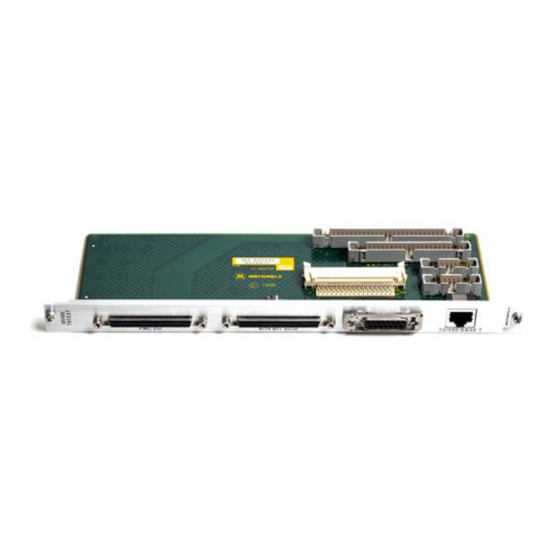
MVME761EXT. Cables are supplied for interconnection between MVME761EXT and the P2 adapters. The MVME761EXT front panel has a SCSI port, PMCIO and two Ethernet ports (10Mbps and 10/100 BaseT). Figure 1-1 shows the MVME761EXT transition module component layout and the front panel. -
Page 16: Figure 1-1. Mvme761Ext Transition Module Front Panel And Component Side
General Description MVME 761EXT Figure 1-1. MVME761EXT Transition Module Front Panel and Component Side http://www.mcg.mot.com/literature... -
Page 17: P2 Adapter Boards
MVME761EXT transition module. 3-row DIN Backplane P2 Adapters for the MVME761EXT One of the 3-row P2 adapters for the MVME761EXT is the MVME761P2-001 (part number 01-W3216F01A), that mounts onto a 3-row, 96-pin P2 backplane connector. It has a 50-pin male connector, J2, that carries the 8-bit SCSI signals from the MVME260x, MVME360x, or MVME460x. -
Page 18: 5-Row Din Backplane P2 Adapter For The Mvme761Ext
Figure 1-3. 3-row DIN Backplane P2 Adapter (01-W3203F02C) 5-row DIN Backplane P2 Adapter for the MVME761EXT The 5-row P2 adapter for the MVME761EXT is the MVME761P2- 011 (part number 01-W3199F01C), which mounts onto a 5-row, 160- pin P2 backplane connector. It has a 68- pin female connector, J1, that carriers 16-bit SCSI signals from the MVME260x, MVME360x, or MVME460x. -
Page 19: Figure 1-4. 5-Row Din Backplane P2 Adapter (Mvme761Ext)
General Information 1999 9701 Figure 1-4. 5-row DIN Backplane P2 Adapter (MVME761EXT) Computer Group Literature Center Web Site... -
Page 20: Connectors And Cables
Connectors and Cables Connectors and Cables The connectors on the MVME761EXT transition module and the P2 Adapters are listed in Tables 1-1, 1-2, 1-3, and 1-4. See Table 1-5 for a list of the cables. See Chapter 3 for the connector pin assignments. -
Page 21: Table 1-3. 3-Row Din Backplane P2 Adapter Connectors (Mvme761Ext)
General Information Table 1-3. 3-Row DIN Backplane P2 Adapter Connectors (MVME761EXT) Type Number Description (01-W3203F0XC) 96-pin female DIN 41612 connector to the chassis backplane Ethernet 20-pin male connector for Ethernet output to J7 for 10/100 BaseT or J8 for 10Mbps on the MVME761EXT module... -
Page 22: Table 1-5. Mvme761Ext Transition Module Cables
Part Number Description 30-W2584C03A 64-line flat ribbon cable with 64-pin female connectors that connects J4 on the MVME761EXT transition module to J3 on the 5-row P2 (PMC I/O cable) adapter; 18 inches long cable supplied with the MVME761EXT 30-W2364E01A 68-line flat ribbon cable with 68-pin female connector and 68-pin... -
Page 23: Specifications
Height: 9.187 inches(233.35 mm) (excluding front panel) Height: 3.200 inches(80.00 mm) Thickness: 0.063 inches (1.60 mm) Cooling Requirements Since no active components exist on the MVME761EXT, there are no direct cooling requirements associated with this board. 1-10 Computer Group Literature Center Web Site... -
Page 24: Emc Compliance
Specifications EMC Compliance The MVME761EXT was tested in an EMC-compliant chassis, and meets the requirements for CE and Class A equipment. For minimum RF emissions, it is essential that you implement the following conditions: Install shielded cables on all external I/O ports... - Page 25 General Information 1-12 Computer Group Literature Center Web Site...
-
Page 26: Introduction
VME761A/IH manual, or to the specific baseboard document. Unpacking the Hardware The MVME761EXT is packed in an anti-static wrapper to protect it Use ESD from static discharge. Motorola strongly recommends that you use an antistatic wrist strap and a conductive foam pad when handling the equipment. -
Page 27: Installing The Transition Module And P2 Adapter
If an ESD station is not available, you can avoid damage resulting from ESD by attaching the ESD wrist strap to an unpainted metal part of the system chassis. Install the MVME761EXT in the system chassis per the following procedure (refer to Figure 2-1... -
Page 28: Mvme761Ext Connection Options
I/O connections available from the baseboard or processor board through the MVME761EXT. For other I/O options refer to the baseboard and MVME761 Transition Module Installation Guides. The following I/O configurations are currently available with the... -
Page 29: Connecting To An 8-Bit Scsi Interface
Connecting to an 8-Bit SCSI Interface Connection to an 8-bit SCSI interface is done from the baseboard through the P2 Adapter to the MVME761EXT. 1. Turn all equipment power OFF and disconnect the power cable from the AC power source. -
Page 30: Figure 2-1. Mvme761Ext 8-Bit Scsi Connection
J2 on the 3-Row Adapter (01-W3216F01A) ENCLOSURE BOUNDARY 2323 9807 Figure 2-1. MVME761EXT 8-bit SCSI Connection 10. Install the chassis cover. Note Make sure that cables are not pinched by the cover. 11. Connect the power cable to the AC power source. -
Page 31: Connecting To An 8/16 Bit Single Ended Scsi Interface
Connecting to an 8/16 Bit Single Ended SCSI Interface Connection to an 8/16-bit Single Ended SCSI interface is done from the baseboard through the P2 Adapter to the MVME761EXT. 1. Turn all equipment power OFF and disconnect the power cable from the AC power source. -
Page 32: Figure 2-2. Mvme761Ext 8/16 Bit Single Ended Scsi Connection
J1 on the 5-Row Adapter (01-W3199F01A) ENCLOSURE BOUNDARY 2324 9807 Figure 2-2. MVME761EXT 8/16 bit Single Ended SCSI Connection 9. Insert the transition module into the chassis slot and tighten the attaching screws. Note Make sure there is good contact with the transverse mounting rails in order to minimize RF emissions. -
Page 33: Connecting To A Pmc I/O Interface
Connecting to a PMC I/O Interface Connection to a PMC I/O interface is done from the baseboard through the P2 Adapter to the MVME761EXT. 1. Turn all equipment power OFF and disconnect the power cable from the AC power source. -
Page 34: Figure 2-3. Mvme761Ext Pmc I/O Connector
P2 ADAPTER J3 on the 5-Row Adapter (01-W3199F01A) ENCLOSURE BOUNDARY 2325 9807 Figure 2-3. MVME761EXT PMC I/O Connector Note Make sure there is good contact with the transverse mounting rails in order to minimize RF emissions. 10. Install the chassis cover. -
Page 35: Connecting To An 8/16 Bit Single Ended Or Differential Scsi Interface.2-10
Connection to an 8/16-bit Single Ended (part number 01- W3203F01C) or Differential (part number 01-W3203F02C) SCSI interface is done from the processor module through the P2 Adapter to the MVME761EXT. 1. Turn all equipment power OFF and disconnect the power cable from the AC power source. -
Page 36: Figure 2-4. Mvme761Ext - 8/16 Bit Single Ended Or Differential Scsi Connection
P2 ADAPTER J11 on the 3-Row Adapter (01-W3203F0XC) ENCLOSURE BOUNDARY Figure 2-4. MVME761EXT - 8/16 bit Single Ended or Differential SCSI Connection Make sure there is good contact with the transverse Note mounting rails in order to minimize RF emissions. -
Page 37: Connecting To A 10Mbps Ethernet Interface
Connecting to a 10Mbps Ethernet Interface Connection to a 10Mbps Ethernet interface is done from the processor module through the P2 Adapter to the MVME761EXT. 1. Turn all equipment power OFF and disconnect the power cable from the AC power source. -
Page 38: Figure 2-5. Mvme761Ext 10Mbps Ethernet Connection
(cable) J10 on the 3-Row Adapter (01-W3203F0XC) ENCLOSURE BOUNDARY Figure 2-5. MVME761EXT 10Mbps Ethernet Connection 9. Install the chassis cover. Make sure that cables are not pinched by the cover. Note 10. Connect the power cable to the AC power source. -
Page 39: Connecting To A 10/100 Base T Interface
Connecting to a 10/100 Base T Interface Connection to a 10/100 BaseT interface is done from the processor module through the P2 Adapter to the MVME761EXT. 1. Turn all equipment power OFF and disconnect the power cable from the AC power source. -
Page 40: Figure 2-6. Mvme761Ext 10/100 Baset Connection
(cable) J10 on the 3-Row Adapter (01-W3203F0XC) ENCLOSURE BOUNDARY Figure 2-6. MVME761EXT 10/100 BaseT Connection 9. Install the chassis cover. Note Make sure that cables are not pinched by the cover. 10. Connect the power cable to the AC power source. - Page 41 Hardware Preparation and Installation 2-16 Computer Group Literature Center Web Site...
-
Page 42: Introduction
3Connector Pin Assignments Introduction This chapter provides the pin assignments for the front panel port connectors on the MVME761EXT transition module, as well as for the SCSI, Ethernet, and PMC I/O connectors on the P2 adapters. MVME761EXT Transition Module Connectors PMC I/O Connector The PMC I/O interface is a 68-pin female connector, J1. -
Page 43: Table 3-1. Pmc I/O Connector Pin Assignments
Connector Pin Assignments Table 3-1. PMC I/O Connector Pin Assignments Signal Signal PMCIO0 PMCIO1 PMCIO2 PMCIO3 PMCIO4 PMCIO5 PMCIO6 PMCIO7 PMCIO8 PMCIO9 PMCIO10 PMCIO11 PMCIO12 PMCIO13 PMCIO14 PMCIO15 PMCIO16 PMCIO17 PMCIO18 PMCIO19 PMCIO20 PMCIO21 PMCIO22 PMCIO23 PMCIO24 Computer Group Literature Center Web Site... - Page 44 MVME761EXT Transition Module Connectors Table 3-1. PMC I/O Connector Pin Assignments (Continued) Signal Signal PMCIO25 PMCIO26 PMCIO27 PMCIO28 PMCIO29 PMCIO30 PMCIO31 http://www.mcg.mot.com/literature...
-
Page 45: Scsi Connector
Connector Pin Assignments SCSI Connector The 8/16 bit single-ended or Differential SCSI interface is a 68-pin connector, J2. The pin assignments and signal mnemonics for this connector are listed in Table 3-2. Table 3-2: 8/16 bit Single-Ended or Differential SCSI pin Assignments Signal Signal... - Page 46 MVME761EXT Transition Module Connectors Table 3-2: 8/16 bit Single-Ended or Differential SCSI pin Assignments Signal Signal SCSI_P55 SCSI_P22 SCSI_P56 SCSI_P23 SCSI_P57 SCSI_P24 SCSI_P58 SCSI_P25 SCSI_P59 SCSI_P26 SCSI_P60 SCSI_P27 SCSI_P61 SCSI_P28 SCSI_P62 SCSI_P29 SCSI_P63 SCSI_P64 DB8_P DB8_N DB9_P DB9_N DB10_P DB10_N...
-
Page 47: 10Mbps Ethernet Connector
Connector Pin Assignments 10Mbps Ethernet Connector The 10Mbps Ethernet interface is a 15 pin female connector, J6. The connector shield is tied to chassis ground. The pin assignments and signal mnemonics for this connector are listed in Table 3-3. Table 3-3. 10Mbps Ethernet Pin Assignments Signal +12VF Computer Group Literature Center Web Site... -
Page 48: 10/100 Baset Connector
MVME761EXT Transition Module Connectors 10/100 BaseT Connector The 10/100BaseT Ethernet interface is a RJ-45 connector, J9. The connector shield is tied to chassis ground. The pin assignments and signal mnemonics for this connector are listed in Table 3-4. Table 3-4. 10/100BaseT Pin Assignments... -
Page 49: Table 3-5. 8-Bit Scsi Connector (3-Row P2 Adapter)
Connector Pin Assignments P2 Adapter Connectors 8-Bit SCSI Connector (3-Row P2 Adapter - part # 01-W3216F01A) The 8-bit SCSI connector on the 3-row DIN backplane P2 Adapter is a 50-pin connector, J2. The pin assignments and signal mnemonics for this connector are listed in Table 3-5. -
Page 50: P2 Adapter Connectors
P2 Adapter Connectors Table 3-5. 8-bit SCSI Connector (3-Row P2 Adapter) (Continued) Signal Signal No Connect http://www.mcg.mot.com/literature... -
Page 51: Scsi Connector (3-Row P2 Adapter - Part # 01-W3203F02C)
Connector Pin Assignments SCSI Connector (3-Row P2 Adapter - Part # 01-W3203F02C) The 8/16-bit Differential SCSI interface on the 3-row DIN backplane P2 Adapter is a 68-pin connector, J11. The pin assignments and signal mnemonics for this connector are listed in Table 3-6. - Page 52 P2 Adapter Connectors Table 3-6. 8/16-bit Differential SCSI Pin Assignments (Continued) Signal Signal SCSI_P55 SCSI_P22 SCSI_P56 SCSI_P23 SCSI_P57 SCSI_P24 SCSI_P58 SCSI_P25 SCSI_P59 SCSI_P26 SCSI_P60 SCSI_P27 SCSI_P61 SCSI_P28 SCSI_P62 SCSI_P29 SCSI_P63 SCSI_P64 DB8_P DB8_N DB9_P DB9_N DB10_P DB10_N DB11_P DB11_N http://www.mcg.mot.com/literature 3-11...
-
Page 53: Scsi Connector (3-Row P2 Adapter - Part # 01-W3203F01C)
Connector Pin Assignments SCSI Connector (3-Row P2 Adapter - Part # 01-W3203F01C) The 8/16-bit SCSI connector on the 3-row DIN backplane P2 Adapter is a 68-pin connector, J11. The pin assignments and signal mnemonics for this connector are listed in Table 3-7. Table 3-7: 16-bit SCSI Connector (3-row P2 Adapter) Signal Signal... - Page 54 P2 Adapter Connectors Table 3-7: 16-bit SCSI Connector (3-row P2 Adapter) Signal Signal SDB8 SDB9 SDB10 SDB11 http://www.mcg.mot.com/literature 3-13...
-
Page 55: Ethernet Connector (3-Row P2 Adapter - Part # 01-W3203F0Xc)
Connector Pin Assignments Ethernet Connector (3-Row P2 Adapter - Part # 01- W3203F0XC) The 10Mbps or 10/100 BaseT Ethernet connector on the 3-Row DIN backplane P2 Adapter is a 20-pin female connector, J10. The pin assignments and signal mnemonics for this connector are listed in Table 3-8. - Page 56 P2 Adapter Connectors Table 3-8. Ethernet Connector (3-Row P2 Adapter) Signal http://www.mcg.mot.com/literature 3-15...
-
Page 57: 16-Bit Scsi Connector (5-Row P2 Adapter - Part # 01-W3199F01A)
Connector Pin Assignments 16-bit SCSI Connector (5-Row P2 Adapter - Part # 01- W3199F01A) The 16-bit SCSI connector on the 5-row DIN backplane P2 Adapter is a 68-pin connector, J1. The pin assignments and signal mnemonics for this connector are listed in Table 3-9. Table 3-9: 16-bit SCSI Connector (5-row P2 Adapter) Signal Signal... - Page 58 P2 Adapter Connectors Table 3-9: 16-bit SCSI Connector (5-row P2 Adapter) Signal Signal SDB8 SDB9 SDB10 SDB11 http://www.mcg.mot.com/literature 3-17...
-
Page 59: Pmc I/O (5-Row P2 Adapter - Part # 01-W3199F01A))
Connector Pin Assignments PMC I/O (5-Row P2 Adapter - part # 01-W3199F01A)) The PMC I/O connector on the 5-row DIN backplane P2 Adapter is a 64-pin connector, J3. The pin assignments and signal mnemonics for this connector are listed in Table 3-10. Table 3-10. - Page 60 P2 Adapter Connectors Table 3-10. PMC I/O Connector (5-Row P2 Adapter) (Continued) Signal Signal PMCIO10 PMCIO26 PMCIO11 PMCIO27 PMCIO12 PMCIO28 PMCIO13 PMCIO29 PMCIO14 PMCIO30 PMCIO15 PMCIO31 http://www.mcg.mot.com/literature 3-19...
- Page 61 Connector Pin Assignments 3-20 Computer Group Literature Center Web Site...
-
Page 62: Motorola Computer Group Documents
To order: Contact your local Motorola sales office, Access the World Wide Web site listed on the back cover of this and other MCG manuals and select “Product Literature”, (USA and Canada only) —Contact the Literature Center via... -
Page 63: Manufacturers' Documents
To further assist your development effort, Motorola has collected some of the non-Motorola documents in this list from the suppliers. Table A-2. Manufacturers’ Documents Publication... - Page 64 Number PowerPC 604 RISC Microprocessor User’s Manual, and MPC604UM/AD PowerPC604 RISC Microprocessor User’s Manual Addendum MPCFPE32B/AD Literature Distribution Center for Motorola Telephone: (800) 441-2447 FAX: (602) 994-6430 or (303) 675-2150 E-mail: ldcformotorola@hibbertco.com MPR604UMU-01 IBM Microelectronics Mail Stop A25/862-1 PowerPC Marketing...
- Page 65 Manufacturers’ Documents Table A-2. Manufacturers’ Documents (Continued) Publication Document Title and Source Number DECchip 21140 PCI Fast Ethernet LAN Controller EC-QC0CA-TE Hardware Reference Manual Digital Equipment Corporation Maynard, Massachusetts DECchip Information Line Telephone (United States and Canada): 1-800-332-2717 TTY (United States only): 1-800-332-2515 Telephone (outside North America): +1-508-568-6868 PC87308VUL (Super I/O Enhanced Sidewinder Lite) Floppy Disk...
- Page 66 Related Documentation Table A-2. Manufacturers’ Documents (Continued) Publication Document Title and Source Number Z8536 CIO Counter/Timer and Parallel I/O Unit DC-8319-00 Product Specification and User’s Manual ® (in Z8000 Family of Products Data Book) Zilog, Inc. 210 East Hacienda Ave., mail stop C1-0 Campbell, California 95008-6600 Telephone: (408) 370-8016 FAX: (408) 370-8056...
-
Page 67: Related Specifications
Related Specifications Related Specifications For additional information, refer to the following table for related specifications. As an additional help, a source for the listed document is also provided. Please note that in many cases, the information is preliminary and the revision levels of the documents are subject to change without notice. - Page 68 Related Documentation Table A-3. Related Specifications (Continued) Publication Document Title and Source Number IEEE - Common Mezzanine Card Specification (CMC) P1386 Draft 2.0 Institute of Electrical and Electronics Engineers, Inc. Publication and Sales Department 345 East 47th Street New York, New York 10017-21633 Telephone: 1-800-678-4333 IEEE - PCI Mezzanine Card Specification (PMC) P1386.1 Draft 2.0...
- Page 69 Document Title and Source Number PowerPC Microprocessor Common Hardware Reference Platform: TB338/D A System Architecture (CHRP), Version 1.0 Literature Distribution Center for Motorola Telephone: (800) 441-2447 FAX: (602) 994-6430 or (303) 675-2150 E-mail: ldcformotorola@hibbertco.com APDA, Apple Computer, Inc. P.O. Box 319...
- Page 70 Related Documentation Table A-3. Related Specifications (Continued) Publication Document Title and Source Number IEEE Standard for Local Area Networks: Carrier Sense Multiple Access IEEE 802.3 with Collision Detection (CSMA/CD) Access Method and Physical Layer Specifications Institute of Electrical and Electronics Engineers, Inc. Publication and Sales Department 345 East 47th Street New York, New York 10017-21633...
- Page 71 Related Specifications A-10 Computer Group Literature Center Web Site...
- Page 72 68 conductor for PMC I/O interface 2-8 for P2 Adapter 2-4 cables as 8-bit SCSI connection 2-4 between MVME761EXT and P2 1-2 to enable active SCSI termination 2-6 connecting to 10Mbps Ethernet interface 2-12 8/16-bit Single Ended SCSI Interface manufacturers’...
- Page 73 SCSI connection restrictions 2-2 operating temperature 1-10 SCSI 8/16-bit connector pin assignments 3-4 SCSI interface as feature of MVME761EXT 1-1 SCSI connector pin assignments 3-12 specifications 1-10 P2 Adapter 1-4, 3-8 static protection 2-1, 2-2 16-bit SCSI connector pin assignments...