ABB Relion 670 Series Installation And Commissioning Manual
Generator protection
Hide thumbs
Also See for Relion 670 Series:
- Technical manual (1432 pages) ,
- Technical reference manual (1232 pages) ,
- Applications manual (944 pages)

Related Manuals for ABB Relion 670 Series


Summary of Contents for ABB Relion 670 Series
- Page 1 ® Relion 670 series Generator protection REG670 Installation and commissioning manual...
- Page 3 Document ID: 1MRK 502 029-UEN Issued: September 2011 Revision: A Product version: 1.2 © Copyright 2011 ABB. All rights reserved...
- Page 4 Copyright This document and parts thereof must not be reproduced or copied without written permission from ABB, and the contents thereof must not be imparted to a third party, nor used for any unauthorized purpose. The software or hardware described in this document is furnished under a license and may be used or disclosed only in accordance with the terms of such license.
- Page 5 In case any errors are detected, the reader is kindly requested to notify the manufacturer. Other than under explicit contractual commitments, in no event shall ABB be responsible or liable for any loss or damage resulting from the use of this manual or the application of the equipment.
- Page 6 (EMC Directive 2004/108/EC) and concerning electrical equipment for use within specified voltage limits (Low-voltage directive 2006/95/EC). This conformity is the result of tests conducted by ABB in accordance with the product standards EN 50263 and EN 60255-26 for the EMC directive, and with the product standards EN 60255-1 and EN 60255-27 for the low voltage directive.
-
Page 7: Table Of Contents
Table of contents Table of contents Section 1 Introduction..............11 Introduction to the installation and commissioning manual....11 About the complete set of manuals for an IED......11 About the installation and commissioning manual.......12 Intended audience...............13 Related documents..............13 Revision notes................14 Section 2 Safety information............15 Warning signs...................15 Caution signs..................16 Note signs..................17... - Page 8 Table of contents Overview................38 Mounting procedure for side-by-side rack mounting....39 IED in the 670 series mounted with a RHGS6 case....39 Side-by-side flush mounting............40 Overview................40 Mounting procedure for side-by-side flush mounting.....41 Mounting the injection unit REX060..........42 Mounting the coupling capacitor unit REX061 and shunt resistor unit REX062..............42 Coupling capacitor unit REX061..........42 Shunt resistor unit REX062............43...
- Page 9 Table of contents Electrical installation..............85 Lightning protection..............85 Section 6 Checking the external optical and electrical connections..............87 Overview...................87 Checking VT circuits.................87 Checking CT circuits.................88 Checking the power supply..............89 Checking the binary I/O circuits............89 Binary input circuits..............89 Binary output circuits..............89 Checking optical connections............89 Section 7 Energizing the IED and REX060........91 Checking the IED operation..............91 Energizing the IED................91...
- Page 10 Table of contents Editing features in graph..............117 Logging measurements to file............118 Section 11 Calibrating injection based 100% stator earth fault protection..............121 Commissioning process..............121 Commissioning tool ICT..............121 Launching injection commissioning tool (ICT)........124 Performing calibration..............125 Acquiring references...............127 Verifying calibration................129 Auditing...................130 Editing features in graph..............132 Logging measurements to file............133 Section 12 Establishing connection and verifying the SPA/IEC- communication ............135...
- Page 11 Table of contents Activating test mode..............150 Connecting test equipment to the IED........150 Verifying analog primary and secondary measurement....151 Releasing the function to be tested...........152 Disturbance report..............152 Introduction................152 Disturbance report settings..........153 Disturbance recorder (DR)...........153 Event recorder (ER) and Event list (EL).......154 Identifying the function to test in the technical reference manual ..................154 Exit test mode................155...
- Page 12 Table of contents Completing the test..............168 Four step phase overcurrent protection OC4PTOC....168 Verifying the settings............168 Completing the test..............170 Instantaneous residual overcurrent protection EFPIOC ...170 Measuring the operate limit of set values......170 Completing the test..............170 Four step residual overcurrent protection EF4PTOC ....170 Four step directional earth fault protection......171 Four step non-directional earth fault protection....171 Completing the test..............172...
- Page 13 Table of contents Verifying settings by secondary injection......189 Completing the test..............190 Accidental energizing protection for synchronous generator AEGGAPC.................191 Verifying the settings............191 Voltage protection................191 Two step undervoltage protection UV2PTUV ......191 Verifying the settings............191 Completing the test..............192 Two step overvoltage protection OV2PTOV ......192 Verifying the settings............192 Completing the test..............192 Two step residual overvoltage protection ROV2PTOV ....193...
- Page 14 Table of contents Overcurrent feature with voltage restraint......205 Overcurrent feature with directionality........206 Over/Undervoltage feature...........207 Completing the test..............207 Rotor earth fault protection with RXTTE4 and general current and voltage protection CVGAPC........207 Testing..................207 Completing the test..............209 Secondary system supervision............209 Current circuit supervision CCSRDIF ........209 Verifying the settings............209 Completing the test..............210 Fuse failure supervision SDDRFUF..........210...
- Page 15 Table of contents Station communication..............225 Multiple command and transmit MultiCmd/MultiTransm....225 Remote communication..............226 Binary signal transfer BinSignReceive, BinSignTransm....226 Section 16 Checking the directionality...........229 About this chapter................229 Overview..................229 Testing the directionality of the distance protection......229 Section 17 Commissioning and maintenance of the fault clearing system............233 Installation and commissioning............233 Commissioning tests..............234...
-
Page 17: Section 1 Introduction
Section 1 1MRK 502 029-UEN A Introduction Section 1 Introduction About this chapter This chapter introduces the user to the manual. Introduction to the installation and commissioning manual 1.1.1 About the complete set of manuals for an IED The user’s manual (UM) is a complete set of five different manuals: Engineeringmanual Installation and Commissioning manual... -
Page 18: About The Installation And Commissioning Manual
Section 1 1MRK 502 029-UEN A Introduction setting parameters and technical data sorted per function. The technical reference manual should be used as a technical reference during the engineering phase, installation and commissioning phase, and during normal service. The Installation and Commissioning Manual (ICM) contains instructions on how to install and commission the protection IED. -
Page 19: Intended Audience
670 series SPA and signal list 1MRK 500 092-WEN IEC 61850 Data objects list for 670 series 1MRK 500 091-WEN Engineering manual 670 series 1MRK 511 240-UEN Buyer’s guide REG 216 1MRB520004-BEN Communication set-up for Relion 670 series 1MRK 505 260-UEN Installation and commissioning manual... -
Page 20: Revision Notes
Section 1 1MRK 502 029-UEN A Introduction More information can be found on www.abb.com/substationautomation. 1.1.5 Revision notes Revision Description First issue for 670 series version 1.2. Minor corrections made Installation and commissioning manual... -
Page 21: Section 2 Safety Information
Section 2 1MRK 502 029-UEN A Safety information Section 2 Safety information About this chapter This chapter contains safety information. Warning signs are presented which urge the user to be careful during certain operations in order to avoid injuries to humans or damage to equipment. -
Page 22: Caution Signs
Section 2 1MRK 502 029-UEN A Safety information Never disconnect the secondary connection of current transformer circuit without short-circuiting the transformer’s secondary winding. Operating a current transformer with the secondary winding open will cause a massive potential build-up that may damage the transformer and may cause injuries to humans. -
Page 23: Note Signs
Section 2 1MRK 502 029-UEN A Safety information Avoid touching the enclosure of the coupling capacitor REX061 unit and the shunt resistor REX062 unit. The surface may be hot during normal operation. Note signs The protection assembly is designed for a maximum continuous current of four times rated value. -
Page 25: Section 3 Overview
Section 3 1MRK 502 029-UEN A Overview Section 3 Overview About this chapter This chapter outlines the installation and commissioning of the IED. Commissioning and installation overview The settings for each function must be calculated before the commissioning task can start. A configuration, done in the configuration and programming tool, must also be available if the IED does not have a factory configuration downloaded. -
Page 27: Section 4 Unpacking And Checking The Ied
Check for transport damages. If transport damage is discovered appropriate action must be taken against the latest carrier and the nearest ABB office or representative should be informed. ABB should be notified immediately if there are any discrepancies in relation to the delivery documents. -
Page 29: Section 5 Installing The Ied
Section 5 1MRK 502 029-UEN A Installing the IED Section 5 Installing the IED About this chapter This chapter describes how to install the IED. Overview The mechanical and electrical environmental conditions at the installation site must be within the limits described in the IED technical data. Dusty, damp places, places susceptible to rapid temperature variations, powerful vibrations and shocks, surge voltages of high amplitude and fast rise time, strong induced magnetic fields or similar extreme conditions should be avoided. -
Page 30: Dimensions
Section 5 1MRK 502 029-UEN A Installing the IED Dimensions 5.2.1 Case without rear cover xx08000164.vsd IEC08000164 V1 EN Figure 1: Case without rear cover Installation and commissioning manual... - Page 31 Section 5 1MRK 502 029-UEN A Installing the IED xx08000166.vsd IEC08000166 V1 EN Figure 2: Case without rear cover with 19” rack mounting kit Case size (mm) A 6U, 1/2 x 19” 265.9 223.7 201.1 252.9 205.7 190.5 203.7 187.6 6U, 3/4 x 19”...
-
Page 32: Case With Rear Cover
Section 5 1MRK 502 029-UEN A Installing the IED 5.2.2 Case with rear cover xx08000163.vsd IEC08000163 V1 EN Figure 3: Case with rear cover Installation and commissioning manual... - Page 33 Section 5 1MRK 502 029-UEN A Installing the IED xx08000165.vsd IEC08000165 V1 EN Figure 4: Case with rear cover and 19” rack mounting kit xx05000503.vsd IEC05000503 V1 EN Figure 5: Rear cover case with details Case size (mm) A 6U, 1/2 x 19” 265.9 223.7 242.1...
-
Page 34: Flush Mounting Dimensions
Section 5 1MRK 502 029-UEN A Installing the IED 5.2.3 Flush mounting dimensions xx08000162.vsd IEC08000162 V1 EN Figure 6: Flush mounting Cut-out dimensions (mm) Case size Tolerance +/-1 +/-1 6U, 1/2 x 19" 210.1 254.3 4.0-10.0 12.5 6U, 3/4 x 19" 322.4 254.3 4.0-10.0... -
Page 35: Side-By-Side Flush Mounting Dimensions
Section 5 1MRK 502 029-UEN A Installing the IED 5.2.4 Side-by-side flush mounting dimensions xx06000182.vsd IEC06000182 V1 EN Figure 7: A 1/2 x 19” size 670 series IED side-by-side with RHGS6. xx05000505.vsd IEC05000505 V1 EN Figure 8: Panel-cut out dimensions for side-by-side flush mounting Case size (mm) Tolerance ±1... -
Page 36: Wall Mounting Dimensions
Section 5 1MRK 502 029-UEN A Installing the IED 5.2.5 Wall mounting dimensions en04000471.vsd IEC04000471 V1 EN Figure 9: Wall mounting Case size (mm) 6U, 1/2 x 19” 292.0 267.1 272.8 390.0 243.0 6U, 3/4 x 19” 404.3 379.4 272.8 390.0 243.0 6U, 1/1 x 19”... - Page 37 Section 5 1MRK 502 029-UEN A Installing the IED The different mounting kits contain all parts needed including screws and assembly instructions. The following mounting kits are available: • Flush mounting kit • 19” Panel (rack) mounting kit • Wall mounting kit •...
-
Page 38: Flush Mounting
Section 5 1MRK 502 029-UEN A Installing the IED 5.3.2 Flush mounting 5.3.2.1 Overview The flush mounting kit are utilized for case sizes: • 1/2 x 19” • 3/4 x 19” • 1/1 x 19” • 1/4 x 19” (RHGS6 6U) Only a single case can be mounted in each cut-out on the cubicle panel, for class IP54 protection. -
Page 39: Mounting Procedure For Flush Mounting
Section 5 1MRK 502 029-UEN A Installing the IED 5.3.2.2 Mounting procedure for flush mounting xx08000161.vsd IEC08000161 V1 EN Figure 11: Flush mounting details. PosNo Description Quantity Type Sealing strip, used to obtain IP54 class. The sealing strip is factory mounted between the case and front plate. -
Page 40: 19" Panel Rack Mounting
Section 5 1MRK 502 029-UEN A Installing the IED See section "Flush mounting dimensions" regarding dimensions. Carefully press the sealing strip (1) around the IEDs collar. Cut the end of the sealing strip a few mm to long to make the joining point (5) tight. The sealing strip is delivered with the mounting kit. -
Page 41: Mounting Procedure For 19" Panel Rack Mounting
Section 5 1MRK 502 029-UEN A Installing the IED 5.3.3.2 Mounting procedure for 19” panel rack mounting xx08000160.vsd IEC08000160 V1 EN Figure 12: 19” panel rack mounting details Description Quantity Type 1a, 1b Mounting angels, which can be mounted, either to the left or right side of the case. -
Page 42: Wall Mounting
Section 5 1MRK 502 029-UEN A Installing the IED 5.3.4 Wall mounting 5.3.4.1 Overview All case sizes, 1/2 x 19”, 3/4 x 19” and 1/1 x 19”, can be wall mounted. It is also possible to mount the IED on a panel or in a cubicle. When mounting the side plates, be sure to use screws that follows the recommended dimensions. -
Page 43: How To Reach The Rear Side Of The Ied
Section 5 1MRK 502 029-UEN A Installing the IED PosNo Description Quantity Type Bushing Screw M4x10 Screw M6x12 or corresponding Mounting bar Screw M5x8 Side plate Procedure Mount the mounting bars onto the wall (4). See section "Wall mounting dimensions" for mounting dimensions. -
Page 44: Side-By-Side 19" Rack Mounting
Section 5 1MRK 502 029-UEN A Installing the IED View from above 80 mm en06000135.vsd IEC06000135 V1 EN Figure 14: How to reach the connectors on the rear side of the IED. PosNo Description Type Screw M4x10 Screw M5x8 Rear protection cover Procedure Remove the inner screws (1), upper and lower on one side. -
Page 45: Mounting Procedure For Side-By-Side Rack Mounting
Section 5 1MRK 502 029-UEN A Installing the IED 5.3.5.2 Mounting procedure for side-by-side rack mounting xx04000456.vsd IEC04000456 V1 EN Figure 15: Side-by-side rack mounting details. PosNo Description Quantity Type Mounting plate 2, 3 Screw M4x6 Mounting angle Procedure Place the two IEDs next to each other on a flat surface. Fasten a side-by-side mounting plate (1). -
Page 46: Side-By-Side Flush Mounting
Section 5 1MRK 502 029-UEN A Installing the IED xx06000180.vsd IEC06000180 V1 EN Figure 16: IED in the 670 series (1/2 x 19”) mounted with a RHGS6 case containing a test switch module equipped with only a test switch and a RX2 terminal base 5.3.6 Side-by-side flush mounting 5.3.6.1... -
Page 47: Mounting Procedure For Side-By-Side Flush Mounting
Section 5 1MRK 502 029-UEN A Installing the IED Please contact factory for special add on plates for mounting FT switches on the side (for 1/2 19" case) or bottom of the relay. 5.3.6.2 Mounting procedure for side-by-side flush mounting xx06000181.vsd IEC06000181 V1 EN Figure 17:... -
Page 48: Mounting The Injection Unit Rex060
Section 5 1MRK 502 029-UEN A Installing the IED Fasten a side-by-side mounting plate (1). Use four of the delivered screws (2, 3). Carefully turn the two IEDs up-side down. Fasten the second side-by-side mounting plate. Use the remaining four screws. Carefully fasten the mounting angles (4) to the sides of the IED. -
Page 49: Shunt Resistor Unit Rex062
Section 5 1MRK 502 029-UEN A Installing the IED IEC11000037-1-en.vsd IEC11000037 V1 EN Figure 19: Measure and drilling plan REX061 shall be mounted close to the generator in order to limit the exposure of the field circuit. Alternatively it can be located in the excitation cubicle. 5.3.8.2 Shunt resistor unit REX062 IEC11000038-1-en.vsd... -
Page 50: Making The Electrical Connection To Reg670
Section 5 1MRK 502 029-UEN A Installing the IED IEC11000039-1-en.vsd IEC11000039 V1 EN Figure 21: REX062 measures and drilling plan REX062 shall be mounted close to the IED. It is recommended that REX060 and REX062 are mounted in the same cubicle as the IED. Making the electrical connection to REG670 5.4.1 IED connectors... - Page 51 Section 5 1MRK 502 029-UEN A Installing the IED Overview Table 1: Basic modules Module Description Combined backplane module (CBM) A backplane PCB that carries all internal signals between modules in an IED. Only the TRM (when included) is not connected directly to this board. Universal backplane module (UBM) A backplane PCB that forms part of the IED backplane with connectors for TRM (when...
-
Page 52: Front Side Connectors
Section 5 1MRK 502 029-UEN A Installing the IED 5.4.1.2 Front side connectors IEC06000179 V1 EN Figure 22: IED front side connector PosNo Description IED serial communication port with RJ45 connector Ethernet cable with RJ45 connectors The cable between PC and the IED serial communication port shall be a crossed-over Ethernet cable with RJ45 connectors. -
Page 53: Rear Side Connectors
Section 5 1MRK 502 029-UEN A Installing the IED 5.4.1.3 Rear side connectors Table 3: Designations for 1/2 x 19” casing with 1 TRM slot Module Rear Positions BIM, BOM, SOM, IOM or X31 and X32 etc. to X51 and X52 X301:A, B, C, D LDCM, IRIG-B or RS485 X302... - Page 54 Section 5 1MRK 502 029-UEN A Installing the IED Table 4: Designations for 3/4 x 19” casing with 1 TRM slot Module Rear Positions BIM, BOM, SOM, IOM or X31 and X32 etc. to X101 and X102 X301:A, B, C, D LDCM, IRIG-B or RS485 X302 LDCM or RS485...
- Page 55 Section 5 1MRK 502 029-UEN A Installing the IED Table 5: Designations for 3/4 x 19” casing with 2 TRM slot Module Rear Positions BIM, BOM, SOM, IOM or X31 and X32 etc. to X71 and X301:A, B, C, D LDCM, IRIG-B or RS485 X302 LDCM or RS485...
- Page 56 Section 5 1MRK 502 029-UEN A Installing the IED Table 6: Designations for 1/1 x 19” casing with 1 TRM slot Module Rear Positions BIM, BOM, X31 and X32 etc. to X161 SOM, IOM or and X162 X301:A, B, C, D LDCM, IRIG-B or X302 RS485...
- Page 57 Section 5 1MRK 502 029-UEN A Installing the IED Table 7: Designations for 1/1 x 19” casing with 2 TRM slots Module Rear Positions BIM, BOM, X31 and X32 etc. to X131 SOM, IOM or and X132 X301:A, B, C, D LDCM, IRIG-B or X302 RS485...
- Page 58 Section 5 1MRK 502 029-UEN A Installing the IED AI01 AI02 AI03 AI04 AI05 AI06 AI07 AI08 AI09 AI10 AI11 AI12 12I, 1A 12I, 5A 9I+3U, 1A 110-220 110-220 110-220 9I+3U, 5A 110-220 110-220 110-220 5I, 1A+4I, 5A+3U 110-220 110-220 110-220 7I+5U, 1A 110-220...
- Page 59 Section 5 1MRK 502 029-UEN A Installing the IED 1MRK002801-AC 15 670 1.2 PG V1 EN Figure 25: mA input module (MIM) 1MRK002801-AC 11 670 1.2 PG V1 EN Figure 24: Binary input module (BIM). Input contacts named XA corresponds to rear position X31, X41, and so on, and input contacts named XB to rear position X32, X42, and so...
- Page 60 Section 5 1MRK 502 029-UEN A Installing the IED 1MRK002801-AC 8 670 1.2 PG V1 EN Figure 26: IED with basic functionality and communication interfaces 1MRK002801-AC 7 670 1.2 PG V1 EN Figure 27: Power supply module (PSM) Installation and commissioning manual...
- Page 61 Section 5 1MRK 502 029-UEN A Installing the IED 1MRK002801-AC 12 670 1.2 PG V1 EN Figure 28: Binary output module (BOM). Output contacts named XA corresponds to rear position X31, X41, and so on, and output contacts named XB to rear position X32, X42, and so on. 1MRK002801-AC 13 670 1.2 PG V1 EN Figure 29: Static output module (SOM)
-
Page 62: Connection Examples For High Impedance Differential Protection
Section 5 1MRK 502 029-UEN A Installing the IED 1MRK002801-AC 14 670 1.2 PG V1 EN Figure 30: Binary in/out module (IOM). Input contacts named XA corresponds to rear position X31, X41, and so on, and output contacts named XB to rear position X32, X42, and so on. 5.4.1.4 Connection examples for high impedance differential protection WARNING! USE EXTREME CAUTION! Dangerously high... - Page 63 Section 5 1MRK 502 029-UEN A Installing the IED SMAI2 AI01 BLOCK AI3P CT 1200/1 ^GRP2L1 Star/Wye ^GRP2L2 AI02 Connected ^GRP2L3 ^GRP2N AI03 TYPE AI04 AI05 AI06 Protected Object L3 (C) L2 (B) L1 (A) L3 (C) L2 (B) CT 1200/1 L1 (A) Star/Wye Connected...
- Page 64 Section 5 1MRK 502 029-UEN A Installing the IED Transformer input module, where the current inputs are located. Note that the CT ratio for high impedance differential protection application must be set as one. • For main CTs with 1A secondary rating the following setting values shall be entered: CTprim = 1A and CTsec = 1A •...
-
Page 65: Connecting To Protective Earth
Section 5 1MRK 502 029-UEN A Installing the IED Description Scheme earthing point Note that it is of outmost importance to insure that only one earthing point exist in such scheme. One-phase plate with setting resistor and metrosil. Necessary connection for the metrosil. Shown connections are applicable for both types of one- phase plate. -
Page 66: Connecting The Power Supply Module
Section 5 1MRK 502 029-UEN A Installing the IED en05000509.vsd IEC05000509 V1 EN Figure 33: Rear view of IED showing earthing points. Description Main protective earth to chassis Earthing screw to Power supply module (PSM) Earthing screw to Transformer input module (TRM). (There is one earth connection per TRM) Use the main protective earth screw (1) for connection to the stations earthing system. -
Page 67: Connecting To Ct And Vt Circuits
Section 5 1MRK 502 029-UEN A Installing the IED 5.4.4 Connecting to CT and VT circuits CTs and VTs are connected to the 24–pole connector of the Transformer input module (TRM) on the rear side of the IED. Connection diagram for TRM is shown in figure 23. - Page 68 Section 5 1MRK 502 029-UEN A Installing the IED If the IED is equipped with a test-switch of type RTXP 24, COMBIFLEX wires with 20 A sockets, 1.5mm² (AWG16) conductor area must be used to connect the auxiliary power. Procedure Connect signals to the female connector All wiring to the female connector should be done before it is plugged into the male part and screwed to the case.
-
Page 69: Making The Screen Connection
Section 5 1MRK 502 029-UEN A Installing the IED xx06000168.vsd IEC06000168 V1 EN Figure 36: Cable connectors PosNo Description Is ferrule, A bridge connector, is used to jump terminal points in a connector. Table 9: Binary I/O connection system Connector type Rated voltage Maximum conductor area Screw compression type... - Page 70 Section 5 1MRK 502 029-UEN A Installing the IED cm) conductors of an adequate cross section, at least 6 mm (AWG10) for single screen connections. External Equipment en06000190.vsd IEC06000190 V1 EN Figure 37: Communication cable installation. PosNo Description Outer shield Protective earth screw Inner shield Inner shielding of the cable shall be earthed at the external...
-
Page 71: Making The Electrical Connection To The Rotor And Stator Injection Equipment
Section 5 1MRK 502 029-UEN A Installing the IED Making the electrical connection to the rotor and stator injection equipment 5.5.1 Connectors for injection unit REX060, coupling capacitor unit REX061 and shunt resistor unit REX062 5.5.1.1 Injection unit REX060 1MRK002501-BA 2 PG V1 EN Figure 38: Designation for REX060 unit casing 1MRK002501-BA 3 PG V1 EN... - Page 72 Section 5 1MRK 502 029-UEN A Installing the IED 1MRK002501-BA 4 PG V1 EN Figure 40: Stator injection module 1MRK002501-BA 5 PG V1 EN Figure 41: Rotor injection module Installation and commissioning manual...
-
Page 73: Coupling Capacitor Unit Rex061
Section 5 1MRK 502 029-UEN A Installing the IED 5.5.1.2 Coupling capacitor unit REX061 1MRK002551-BA 1 PG V1 EN Figure 42: Designation for capacitor unit casing 1MRK002551-BA 2 PG V1 EN Figure 43: Coupling capacitor module Installation and commissioning manual... -
Page 74: Shunt Resistor Unit Rex062
Section 5 1MRK 502 029-UEN A Installing the IED 5.5.1.3 Shunt resistor unit REX062 1MRK002556-BA 1 PG V1 EN Figure 44: Designation for shunt resistor unit casing 1MRK002556-BA 2 PG V1 EN Figure 45: Shunt resistor module Installation and commissioning manual... -
Page 75: Connecting Injection Unit Rex060, Coupling Capacitor Unit Rex061 And Shunt Resistor Unit Rex062
Section 5 1MRK 502 029-UEN A Installing the IED 5.5.2 Connecting injection unit REX060, coupling capacitor unit REX061 and shunt resistor unit REX062 The figures below show typical installations for rotor and stator earth fault protection, where injection unit REX060, coupling capacitor unit REX061 and with and without shunt resistor unit REX062. - Page 76 Section 5 1MRK 502 029-UEN A Installing the IED IEC11000225.ai IEC11000225 V1 EN Figure 47: Stator connection example, with REX062 IEC11000236-1-en IEC11000236 V1 EN Figure 48: Stator connection example, without REX062 For connection details regarding REX060, REX061 and REX062, refer to REG670 Technical Reference manual, section Connection diagram Installation and commissioning manual...
- Page 77 Section 5 1MRK 502 029-UEN A Installing the IED REX060 connections Table 10: Power X11 Signal Ready, Power off NO binary out Power off common binary out Fail, Power off NC binary out Power input positive Power input negative Table 11: Stator IED and sense connection X61 Signals Block injection, 220V binary in...
- Page 78 Section 5 1MRK 502 029-UEN A Installing the IED Table 13: Rotor injection and IED connection X81 Signal Block injection, 220V binary in Block injection, 110V binary in Block injection, 48V binary in Block injection, Common binary in Injection Blocked NC binary out Voltage/Current Saturation NO binary out Common binary out Voltage A, analog out...
- Page 79 Section 5 1MRK 502 029-UEN A Installing the IED REX061 Capacitor unit connections Table 15: Injection and rotor connection X1 Signal Rotor positive pole Positive pole Negative pole Rotor negative pole Rotor injection Injection ground. Internally connected to chassis and PE Table 16: Measurment connector X2 Signal...
-
Page 80: Connecting And Setting Voltage Inputs
Section 5 1MRK 502 029-UEN A Installing the IED X1 connector. Connect each signal connector terminal of screw compression type with one 0.14 to 6 mm wire or with two 0.14 to 1.5 mm wires. Grounding (PE). Protective earth is a separate 4 mm screw terminal. 5.5.3 Connecting and setting voltage inputs There are two different methods for connecting the IED to the REX060 injection... - Page 81 Section 5 1MRK 502 029-UEN A Installing the IED REX060 VOLTAGE MEASURE (U) STATOR MODULE SIM CURRENT MEASURE (U) VOLTAGE MEASURE (U) ROTOR MODULE RIM CURRENT MEASURE (U) IEC11000209-1-en.vsd IEC11000209 V1 EN Figure 50: Separate analogue inputs for stator STTIPHIZ and rotor ROTIPHIZ protection If sufficient number of analog voltage inputs are available in IED, alternative 2 with separate inputs for STTIPHIZ and ROTIPHIZ is recommended.
-
Page 82: Making The Optical Connections
Section 5 1MRK 502 029-UEN A Installing the IED Making the optical connections 5.6.1 Connecting station communication interfaces The IED can be equipped with an optical ethernet module (OEM), see figure 26, needed for IEC 61850 communication and a serial communication module (SLM), see figure for LON, SPA, IEC 60870–5–103 or DNP3 communication. -
Page 83: Connecting Remote Communication Interfaces Ldcm
Section 5 1MRK 502 029-UEN A Installing the IED 5.6.2 Connecting remote communication interfaces LDCM The Line Data Communication Module (LDCM), see figure is the hardware used for the transfer of binary and analog signal data between IEDs in different protection schemes on the IEEE/ANSI C37.94 protocol. - Page 84 Section 5 1MRK 502 029-UEN A Installing the IED Name 2-wire Name 4-wire Description 2–wire: Connect pin X1:1 to pin X1:6 and pin X1:2 to pin X1:5. Termination (2-wire): Connect pin X1:1 to pin X1:3 Termination (4-wire): Connect pin X1:1 to pin X1:3 and pin X1:4 to pin X1:6 The distance between earth points should be <...
- Page 85 Section 5 1MRK 502 029-UEN A Installing the IED External Equipment (PC) PE 1) 3) en07000141.vsd IEC07000141 V1 EN Figure 52: Communication cable installation, 2-wire Where: The inner shields shall be connected together (with an isolated terminal block) and only have one earthing point in the whole system, preferably at the external equipment (PC).
- Page 86 Section 5 1MRK 502 029-UEN A Installing the IED External Equipment (PC) PE 1) 3) en07000142.vsd IEC07000142 V1 EN Figure 53: Communication cable installation, 4-wire Where: The inner shields shall be connected together (with an isolated terminal block) and only have one earthing point in the whole system, preferably at the external equipment (PC).
-
Page 87: Installing The Serial Communication Cable For Rs485 Spa/Iec
Section 5 1MRK 502 029-UEN A Installing the IED en03000110.vsd IEC03000110 V1 EN Figure 54: Cable contact, Phoenix: MSTB2.5/6-ST-5.08 1757051 Where: is cable is screw Pair separator Pair Shield Drain wire Conductor Overall shield Separator Jacket en07000139.vsd IEC07000139 V1 EN Figure 55: Cross section of communication cable The EIA standard RS-485 specifies the RS485 network. - Page 88 Section 5 1MRK 502 029-UEN A Installing the IED Normative references EIA Standard RS-485 - Electrical Characteristics of Generators and Receivers for Balanced Digital Multipoint Systems Transmission method RS-485 differential bipolar signaling Differential signal levels Two differential signal levels are defined: A+ =line A positive with respect to line B A- =line A negative with respect to line B Galvanic isolation...
-
Page 89: Data On Rs485 Serial Communication Module Cable
Section 5 1MRK 502 029-UEN A Installing the IED ExV is supplied by the Node at end of the Bus Segment The specifications of the components are: a) Ru + 5 V to Signal B = 390 W, 0.25 W ±2.5% b) Rt Signal B to Signal A = 220 W, 0.25 W ±2.5%... - Page 90 Section 5 1MRK 502 029-UEN A Installing the IED xx05000510.vsd IEC05000510 V1 EN PosNO Description GPS antenna TNC connector Console, 78x150 mm Mounting holes 5.5 mm Tab for securing of antenna cable Vertical mounting position (on antenna mast etc.) Horizontal mounting position Mount the antenna and console clear of flat surfaces such as buildings walls, roofs and windows to avoid signal reflections.
-
Page 91: Electrical Installation
Section 5 1MRK 502 029-UEN A Installing the IED 99001046.vsd IEC99001046 V1 EN Figure 57: Antenna line-of-sight 5.8.2 Electrical installation Use a 50 ohm coaxial cable with a male TNC connector on the antenna end and a male SMA connector on the receiver end to connect the antenna to the IED. Choose cable type and length so that the total attenuation is max. -
Page 93: Section 6 Checking The External Optical And Electrical Connections
Section 6 1MRK 502 029-UEN A Checking the external optical and electrical connections Section 6 Checking the external optical and electrical connections About this chapter This chapter describes what to check to ensure correct connection to the external circuitry, such as the auxiliary power supply, CT’s and VT’s. These checks must be made with the protection IED de-energized. -
Page 94: Checking Ct Circuits
Section 6 1MRK 502 029-UEN A Checking the external optical and electrical connections Checking CT circuits Check that the wiring is in strict accordance with the supplied connection diagram. Correct possible errors before continuing to test the circuitry. The CTs must be connected in accordance with the circuit diagram provided with the IED, both with regards to phases and polarity. -
Page 95: Checking The Power Supply
Section 6 1MRK 502 029-UEN A Checking the external optical and electrical connections Checking the power supply Check that the auxiliary supply voltage remains within the permissible input voltage range under all operating conditions. Check that the polarity is correct before powering the IED. -
Page 97: Section 7 Energizing The Ied And Rex060
Section 7 1MRK 502 029-UEN A Energizing the IED and REX060 Section 7 Energizing the IED and REX060 About this chapter This chapter describes the start-up sequence and what to check once the IED has been energized. Checking the IED operation Check all connections to external circuitry to ensure that the installation was made correctly, before energizing the IED and carrying out the commissioning procedures. -
Page 98: Design
Section 7 1MRK 502 029-UEN A Energizing the IED and REX060 t (s) xx04000310.vsd IEC04000310 V1 EN Figure 58: Typical IED start-up sequence 1 IED energized. Green LED instantly starts flashing 2 LCD lights up and "IED startup" is displayed 3 The main menu is displayed. - Page 99 Section 7 1MRK 502 029-UEN A Energizing the IED and REX060 en05000056.eps IEC05000056-CALLOUT V1 EN Figure 59: Medium size graphic HMI 1 Status indication LEDs 2 LCD 3 Indication LEDs 4 Label 5 Local/Remote LEDs 6 RJ45 port 7 Communication indication LED 8 Keypad Installation and commissioning manual...
-
Page 100: Checking The Self Supervision Signals
Section 7 1MRK 502 029-UEN A Energizing the IED and REX060 Checking the self supervision signals 7.4.1 Reconfiguring the IED I/O modules configured as logical I/O modules (BIM, BOM or IOM) are supervised. I/O modules that are not configured are not supervised. Each logical I/O module has an error flag that indicates signal or module failure. -
Page 101: Self Supervision Hmi Data
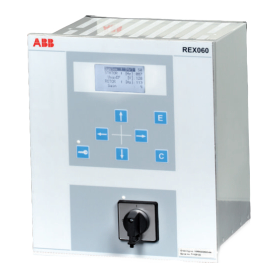
REX060 start up sequence When the injection unit REX060 is energized, the ABB logotype is shown followed by current REX060 revision status. When the start up sequence is completed, the main menu (normal display content) is shown. The duration of the start up sequence is a few seconds. -
Page 103: Section 8 Set Up The Pcm600 Communication Link Per Ied
Section 8 1MRK 502 029-UEN A Set up the PCM600 communication link per IED Section 8 Set up the PCM600 communication link per IED About this chapter This chapter describes the communication between the IED and PCM600. Setting up communication between PCM600 and the IED The communication between the IED and PCM600 is independent of the used communication protocol within the substation or to the NCC. - Page 104 Section 8 1MRK 502 029-UEN A Set up the PCM600 communication link per IED factory IP address when the complete IED is delivered. This is not given when an additional Ethernet interface is installed or an interface is replaced. • The default IP address for the IED front port is 10.1.150.3 and the corresponding subnetwork mask is 255.255.255.0, which can be set via the local HMI path Main menu/Settings/General settings/Communication/...
- Page 105 Section 8 1MRK 502 029-UEN A Set up the PCM600 communication link per IED Select Network Connections in the PC. IEC09000355-1-en.vsd IEC09000355 V1 EN Figure 61: Select: Network connections Select Properties in the status window. IEC09000356-1-en.vsd IEC09000356 V1 EN Figure 62: Right-click Local Area Connection and select Properties Select the TCP/IP protocol from the list of configured components using this connection and click Properties.
- Page 106 Section 8 1MRK 502 029-UEN A Set up the PCM600 communication link per IED IEC09000357-1-en.vsd IEC09000357 V1 EN Figure 63: Select the TCP/IP protocol and open Properties Select Use the following IP address and define IP address and Subnet mask if the front port is used and if the IP address is not set to be obtained automatically by the IED, see Figure...
- Page 107 Section 8 1MRK 502 029-UEN A Set up the PCM600 communication link per IED Setting up the PC to access the IED via a network This task depends on the used LAN/WAN network. PC and IED must belong to the same subnetwork.
-
Page 109: Section 9 Configuring The Ied And Changing Settings
Section 9 1MRK 502 029-UEN A Configuring the IED and changing settings Section 9 Configuring the IED and changing settings About this chapter This chapter describes how to change IED settings, either through a PC or the local HMI, and download a configuration to the IED in order to make commissioning possible. -
Page 110: Entering Settings Through The Local Hmi
Section 9 1MRK 502 029-UEN A Configuring the IED and changing settings Use the configuration tools in PCM600 to verify that the IED has the expected configuration. A new configuration is done with the application configuration tool. The binary outputs can be selected from a signal list where the signals are grouped under their function names. -
Page 111: Downloading Settings And Configuration From A Pc
Section 9 1MRK 502 029-UEN A Configuring the IED and changing settings The primary CT data are entered via the HMI menu under Main menu/Settings/ General Settings/Analog modules/AnalogInputs The following parameter shall be set for every current transformer connected to the IED: Table 19: CT configuration... -
Page 113: Section 10 Calibrating Injection Based Sensitive Rotor Earth Fault Protection
Section 10 1MRK 502 029-UEN A Calibrating injection based sensitive rotor earth fault protection Section 10 Calibrating injection based sensitive rotor earth fault protection 10.1 Commissioning process The commissioning process utilizes the commissioning tool ICT. The instructions for the process cover installation, calibration, commissioning, monitoring and auditing for the sensitive rotor earth fault ROTIPHIZ function. - Page 114 Section 10 1MRK 502 029-UEN A Calibrating injection based sensitive rotor earth fault protection set injection frequency (for example, due to accuracy of the REX060 hardware). Set manually the actual frequency value measured by ICT in the IED via PST. The high accuracy of this frequency is essential for proper operation of the protection under different operating conditions.
-
Page 115: Launching Injection Commissioning Tool (Ict)
Section 10 1MRK 502 029-UEN A Calibrating injection based sensitive rotor earth fault protection user stops the sequence by acceptance of the measurement. The result is stored for later calculations. After the three measurements ICT calculates the complex factors k1 and k2. The reference impedance RefR1 + jRefX1 is also calculated. -
Page 116: Performing Calibration
Section 10 1MRK 502 029-UEN A Calibrating injection based sensitive rotor earth fault protection IEC11000222-1-en.vsd IEC11000222 V1 EN Figure 66: ICT toolbar Select the Installing tab if it was not already selected by default after the ICT was launched. The first thing that needs to be ensured prior to calibration is that the measured voltage and current signal on the injected frequency is present/ found, and that the amplitude of these is within the permitted limits. - Page 117 Section 10 1MRK 502 029-UEN A Calibrating injection based sensitive rotor earth fault protection From the Calibration tab, select the first sub tab, i.e. Step1: Calibration step 1. Make sure you have not attached any additional impedance in parallel with the rotor.
- Page 118 12.1. If a failure is indicated during one or more check(s), follow the instructions/tips provided by the ICT in the Calibration result field. 12.2. If these tips do not solve the issue, then contact ABB Support. IEC11000221-1-en.vsd IEC11000221 V1 EN...
-
Page 119: Acquiring References
Section 10 1MRK 502 029-UEN A Calibrating injection based sensitive rotor earth fault protection 10.5 Acquiring references To detect different operation conditions of the generator and select proper impedance reference requires logic outside the injection function. Therefore changing/switching impedance reference is not described here but in a separate application note 1MRG005030 Application example for injection based 100% Stator EF and Sensitive Rotor EF protection. -
Page 120: Verifying Calibration
Section 10 1MRK 502 029-UEN A Calibrating injection based sensitive rotor earth fault protection settled, and also if the average impedance is based on enough values so that statistically the signal noise is “filtered out”. This results in a fairly accurate impedance measurement which can be used as an alternative reference. - Page 121 Section 10 1MRK 502 029-UEN A Calibrating injection based sensitive rotor earth fault protection By default the measured absolute impedance is plotted, however there are several items that can be viewed when monitoring. To see these, select the available quantities under the Viewed quantity drop-down menu under the Monitoring tab.
-
Page 122: Auditing
Section 10 1MRK 502 029-UEN A Calibrating injection based sensitive rotor earth fault protection • After completion of the calibration step • Before leaving the ICT Tool 10.7 Auditing During installations, calibrations and commissions the ICT generates reports for each of the steps and collects them under the Auditing tab. See the procedures below on how to view and delete reports as well as generate logs from reports. -
Page 123: Editing Features In Graph
Section 10 1MRK 502 029-UEN A Calibrating injection based sensitive rotor earth fault protection • In the short cut menu, right click and select Generate log. • Click the Generate log button. Besides generating a report you can also generate a log file with the same information as for the report. -
Page 124: Logging Measurements To File
Section 10 1MRK 502 029-UEN A Calibrating injection based sensitive rotor earth fault protection IEC11000052-1-en.vsd GUID-261171B2-59CD-4248-B873-39A2BC3CD1F1 V1 EN Figure 74: Zooming via area selection of a part of the graph • Press PgUp key on the keyboard to zoom in and PgDn to zoom out. Cancel a zoom in the following ways: •... - Page 125 Section 10 1MRK 502 029-UEN A Calibrating injection based sensitive rotor earth fault protection value is 1 hour. The period can be adjusted before the logging is started, if needed. The logging can be stopped by selecting the Stop button. You can open the file in notepad or MS Excel.
-
Page 127: Section 11 Calibrating Injection Based 100% Stator Earth Fault Protection
Section 11 1MRK 502 029-UEN A Calibrating injection based 100% stator earth fault protection Section 11 Calibrating injection based 100% stator earth fault protection 11.1 Commissioning process The commissioning process utilizes the commissioning tool ICT. The instructions for the process cover installation, calibration, commissioning, monitoring and auditing for the 100% stator earth fault STTIPHIZ function. - Page 128 Section 11 1MRK 502 029-UEN A Calibrating injection based 100% stator earth fault protection set injection frequency (e.g. due to accuracy of the REX060 hardware). Set manually the actual frequency value measured by ICT in the IED via PST.Check that the selected injection frequency setting on REX060 is equal to the FreqInjected setting in parameter setting.
- Page 129 Section 11 1MRK 502 029-UEN A Calibrating injection based 100% stator earth fault protection diagram. The user stops the sequence by acceptance of the measurement. The result is stored for later calculations. • Calibration sequence 2: A known resistor is connected to the generator neutral point in parallel with the stator neutral point resistor.
-
Page 130: Launching Injection Commissioning Tool (Ict)
Section 11 1MRK 502 029-UEN A Calibrating injection based 100% stator earth fault protection If more than one reference impedance is to be used there must be a logic configured to detect such changes in the operation states when the reference impedance must be changed, and when a change in the function block must be initiated. -
Page 131: Performing Calibration
Section 11 1MRK 502 029-UEN A Calibrating injection based 100% stator earth fault protection Activate the injection by turning the injection switch to on position on the injection unit REX060. Select the Start reading from IED button from the ICT toolbar to start performing continuous measurements. - Page 132 12.1. If a failure is indicated during one or more check(s), follow the instructions/tips provided by the ICT in the Calibration result field. 12.2. If these tips do not solve the issue, then contact ABB Support. Installation and commissioning manual...
-
Page 133: Acquiring References
Section 11 1MRK 502 029-UEN A Calibrating injection based 100% stator earth fault protection IEC11000048-2-en.vsd GUID-D024D8B7-45F3-42D1-AAA3-488A2996267B V1 EN Figure 79: ICT calibration tab 4 13. Before proceeding any further make sure that you have removed the short- circuit that was applied during calibration step 3. 14. - Page 134 Section 11 1MRK 502 029-UEN A Calibrating injection based 100% stator earth fault protection Ensure that the generator is in a state where the reference must be set (for example normal operation). To start, select the Commissioning tab. In the Reference impedance selection drop-down menu. select Reference 2. To start reading the measurements, click the Start reading from IED button in the ICT toolbar.
-
Page 135: Verifying Calibration
Section 11 1MRK 502 029-UEN A Calibrating injection based 100% stator earth fault protection 11.6 Verifying calibration After the calibration is performed, it is appropriate to verify that known faults are measured as expected and that the function is indicating trips and alarms when it should, in other words that the calibration was successful. -
Page 136: Auditing
Section 11 1MRK 502 029-UEN A Calibrating injection based 100% stator earth fault protection Due to the fact that no fault theoretically equals infinite fault resistance and viewing this only plots unreliable values, it is better to view the fault conductance, which is zero in this case. - Page 137 Section 11 1MRK 502 029-UEN A Calibrating injection based 100% stator earth fault protection To view the reports, go to the Auditing tab. IEC11000049-1-en.vsd GUID-8348F60B-9BF5-4018-9740-0FA3371B0F9F V1 EN Figure 82: Auditing tab Open and view each report. View reports in one of the following ways: •...
-
Page 138: Editing Features In Graph
Section 11 1MRK 502 029-UEN A Calibrating injection based 100% stator earth fault protection 11.8 Editing features in graph You can do the following operations on the graph during calibration, commissioning and monitoring: • Zoom in • Zoom out • Cancel zoom •... -
Page 139: Logging Measurements To File
Section 11 1MRK 502 029-UEN A Calibrating injection based 100% stator earth fault protection Cancel a zoom in the following ways: • Right click a graph and select Cancel Zoom in the shortcut menu. The graph area is squeezed to the original size. •... -
Page 141: Section 12 Establishing Connection And Verifying The Spa/Iec- Communication
Section 12 1MRK 502 029-UEN A Establishing connection and verifying the SPA/IEC- communication Section 12 Establishing connection and verifying the SPA/IEC- communication About this chapter This chapter contains instructions on how to establish connection and verify that the SPA/IEC-communication operates as intended, when the IED is connected to a monitoring or control system via the rear SPA/IEC port. -
Page 142: Entering Iec Settings
Section 12 1MRK 502 029-UEN A Establishing connection and verifying the SPA/IEC- communication 12.1.2 Entering IEC settings When using the IEC protocol, the rear SPA/IEC port must be set for IEC use. Two types of interfaces can be used: • for plastic fibres with connector type HFBR •... -
Page 143: Verifying Iec Communication
Section 12 1MRK 502 029-UEN A Establishing connection and verifying the SPA/IEC- communication 12.2.2 Verifying IEC communication To verify that the IEC communication with the IEC master system is working, there are some different methods. Choose one of the following. Procedure Check that the master system time-out for response from the IED, for example after a setting change, is >... -
Page 144: Optical Budget Calculation For Serial Communication With Spa/Iec
Section 12 1MRK 502 029-UEN A Establishing connection and verifying the SPA/IEC- communication Remote monitoring Local monitoring system with system with PCM600 PCM600 Teleph Teleph modem modem Optical to electrical converter, e.g. SPA-ZC 22 en05000672.vsd or Fiberdata modem IEC05000672 V2 EN Figure 85: Example of SPA communication structure for a station monitoring system... -
Page 145: Section 13 Establishing Connection And Verifying The Lon Communication
Section 13 1MRK 502 029-UEN A Establishing connection and verifying the LON communication Section 13 Establishing connection and verifying the LON communication About this chapter This chapter explains how to set up LON communication and how to verify that LON communication is up and running. 13.1 Communication via the rear ports 13.1.1... -
Page 146: The Lon Protocol
Section 13 1MRK 502 029-UEN A Establishing connection and verifying the LON communication Control Center Station HSI MicroSCADA Gateway Star coupler RER 111 IEC05000663-1-en.vsd IEC05000663 V2 EN Figure 86: Example of LON communication structure for a substation automation system An optical network can be used within the substation automation system. This enables communication with the IEDs in the 670 series through the LON bus from the operator’s workplace, from the control center and also from other IEDs via bay- to-bay horizontal communication. -
Page 147: Hardware And Software Modules
Section 13 1MRK 502 029-UEN A Establishing connection and verifying the LON communication 13.2.2 Hardware and software modules The hardware needed for applying LON communication depends on the application, but one very central unit needed is the LON Star Coupler and optical fibres connecting the star coupler to the IEDs. - Page 148 Section 13 1MRK 502 029-UEN A Establishing connection and verifying the LON communication Table 23: Setting parameters for the LON communication Parameter Range Default Unit Parameter description DomainID Domain identification number SubnetID* 0 - 255 Subnet identification number Step: 1 NodeID* 0 - 127 Node identification number...
-
Page 149: Optical Budget Calculation For Serial Communication With Lon
Section 13 1MRK 502 029-UEN A Establishing connection and verifying the LON communication 13.2 Optical budget calculation for serial communication with LON Table 27: Example Distance 1 km Distance10 m Glass Plastic Maximum attenuation -11 dB - 7 dB 4 dB/km multi mode: 820 nm - 62.5/125 um 4 dB 0.3 dB/m plastic: 620 nm - 1mm 3 dB... -
Page 151: Section 14 Establishing Connection And Verifying The Iec 61850 Communication
Section 14 1MRK 502 029-UEN A Establishing connection and verifying the IEC 61850 communication Section 14 Establishing connection and verifying the IEC 61850 communication About this chapter This chapter contains instructions on how to establish connection and verify that the IEC 61850 communication operates as intended, when the IED is connected to an Ethernet network via the optical ports of the OEM. -
Page 152: Verifying The Communication
Section 14 1MRK 502 029-UEN A Establishing connection and verifying the IEC 61850 communication Set Operation to On and GOOSE to the port used (for example OEM311_AB). Enable redundant IEC 61850-8-1 communication for port AB and CD 2.1. Enable redundant communication. Navigate to: Main menu/Settings/general settings/Communication/ Ethernet configuration/Rear OEM - redundant PRP Set values for Operation, IPAddress and IPMask. -
Page 153: Section 15 Verifying Settings By Secondary Injection
Section 15 1MRK 502 029-UEN A Verifying settings by secondary injection Section 15 Verifying settings by secondary injection About this chapter This chapter describes how to verify that protection functions operate correctly and according to their settings. It is preferable that only the tested function is in operation. 15.1 Overview IED test requirements:... -
Page 154: Preparing For Test
Section 15 1MRK 502 029-UEN A Verifying settings by secondary injection Prepare the IED for test before testing a particular function. Consider the logic diagram of the tested protection function when performing the test. All included functions in the IED are tested according to the corresponding test instructions in this chapter. -
Page 155: Preparing The Connection To The Test Equipment
Section 15 1MRK 502 029-UEN A Verifying settings by secondary injection handling tool. The content of reports generated by the Disturbance handling tool can be configured which makes the work more efficient. For example, the tool may be configured to only show time tagged events and to exclude analog information and so on. -
Page 156: Activating Test Mode
Section 15 1MRK 502 029-UEN A Verifying settings by secondary injection are given a chance to decay before the trip circuits are restored. When the latches are released, the handle can be completely withdrawn from the test switch, restoring the trip circuits to the protection IED. If a test switch is not used, take measures according to provided circuit diagrams. -
Page 157: Verifying Analog Primary And Secondary Measurement
Section 15 1MRK 502 029-UEN A Verifying settings by secondary injection IN (I4,I5) UN (U4,U5) TRIP L1 TRIP L2 TRIP L3 IEC 61850 IEC09000652-1-en.vsd IEC09000652 V1 EN Figure 87: Connection example of the test equipment to the IED when test equipment is connected to the transformer input module 15.2.5 Verifying analog primary and secondary measurement... -
Page 158: Releasing The Function To Be Tested
Section 15 1MRK 502 029-UEN A Verifying settings by secondary injection 15.2.6 Releasing the function to be tested Release or unblock the function to be tested. This is done to ensure that only the function or the chain of functions to be tested are in operation and that other functions are prevented from operating. -
Page 159: Disturbance Report Settings
Section 15 1MRK 502 029-UEN A Verifying settings by secondary injection • Disturbance recorder • Event list • Event recorder • Trip value recorder • Indications If the disturbance report is set on, then its sub-functions are also set up and so it is not possible to only switch these sub-functions off. -
Page 160: Event Recorder (Er) And Event List (El)
Section 15 1MRK 502 029-UEN A Verifying settings by secondary injection Ethernet port (RJ-45) on the front. The PCM600 software package must be installed in the PC. Disturbance upload can be performed by the use of PCM600 or by any third party tool with IEC 61850 protocol. -
Page 161: Exit Test Mode
Section 15 1MRK 502 029-UEN A Verifying settings by secondary injection 15.2.9 Exit test mode The following procedure is used to return to normal operation. Navigate to the test mode folder. Change the On setting to Off. Press the 'E' key and the left arrow key. Answer YES, press the 'E' key and exit the menus. -
Page 162: Differential Protection
Section 15 1MRK 502 029-UEN A Verifying settings by secondary injection 15.4 Differential protection 15.4.1 Generator differential protection GENPDIF Prepare the IED for verification of settings outlined in section "Overview" section "Preparing for test" in this chapter. 15.4.1.1 Verifying the settings Go to Main menu/Test/Function test modes/Differential protection and make sure all other functions, configured to the same current transformer inputs as the generator differential protection, are set off. -
Page 163: Transformer Differential Protection T2Wpdif And T3Wpdif
Section 15 1MRK 502 029-UEN A Verifying settings by secondary injection 15.4.2 Transformer differential protection T2WPDIF and T3WPDIF Prepare the IED for verification of settings outlined in section "Overview" section "Preparing for test" in this chapter. 15.4.2.1 Verifying the settings Go to Main menu/Test/Function test modes/Differential protection and make sure that the restricted earth fault protection, low impedance function REFPDIF is set to Off and that the four step residual overcurrent function... -
Page 164: Completing The Test
Section 15 1MRK 502 029-UEN A Verifying settings by secondary injection For more detailed formulas please refer to the application manual. 15.4.2.2 Completing the test Continue to test another function or end the test by changing the Test mode setting to Off. -
Page 165: High Impedance Differential Protection Hzpdif
Section 15 1MRK 502 029-UEN A Verifying settings by secondary injection 15.4.4 High impedance differential protection HZPDIF Prepare the IED for verification of settings outlined in section "Overview" section "Preparing for test" in this chapter. 15.4.4.1 Verifying the settings Connect single-phase or three-phase test set to inject the operating voltage. The injection shall be on the primary side of the stabilizing resistor. -
Page 166: Completing The Test
Section 15 1MRK 502 029-UEN A Verifying settings by secondary injection 15.4.4.2 Completing the test Continue to test another function or end the test by changing the Test mode setting to Off. Restore connections and settings to their original values, if they were changed for testing purposes. -
Page 167: Phase-To-Phase Faults
Section 15 1MRK 502 029-UEN A Verifying settings by secondary injection 15.5.1.1 Phase-to-phase faults ZAngPP Ohm/phase IEC07000009-3-en.vsd IEC07000009 V3 EN Figure 88: Proposed test points for phase-to-phase fault Label Description ZPP1 The measured impedance for phase-to-phase fault at point 1 (zone reach ZPP) ohm/ phase. -
Page 168: Pole Slip Protection Pspppam
Section 15 1MRK 502 029-UEN A Verifying settings by secondary injection ZAngPE Ohm/phase en07000010.vsd IEC07000010 V2 EN Figure 89: Proposed test points for phase-to-earth faults Label Description ZPE1 The measured impedance for phase-to-earth fault at point 1 (zone reach ZPE) ohm/ phase. -
Page 169: Verifying The Settings
Section 15 1MRK 502 029-UEN A Verifying settings by secondary injection 15.5.2.1 Verifying the settings It is assumed that setting of the pole slip protection function PSPPPAM is done according to impedances as seen in figure and figure 91. The test is done by means of injection of three-phase current and three-phase voltage from a modern test device. - Page 170 Section 15 1MRK 502 029-UEN A Verifying settings by secondary injection Zone 1 Zone 2 X’ Pole slip impedance movement Zone 2 TripAngle Zone 1 WarnAngle IEC07000099_2_en.vsd IEC07000099 V2 EN Figure 90: Setting of the pole slip protection PSPPPAM Installation and commissioning manual...
-
Page 171: Completing The Test
Section 15 1MRK 502 029-UEN A Verifying settings by secondary injection Imin > 0.10 IBase Umax < 0.92 UBase START 0.2 £ f(Ucos) £ 8Hz d ³ StartAngle ZONE1 Z cross line ZA - ZC ZONE2 Z cross line ZC - ZB Counter b a ³... - Page 172 Section 15 1MRK 502 029-UEN A Verifying settings by secondary injection X and check that this reading corresponds to the injected impedance. No start or trip signals shall be activated. Feed the IED with current and voltage corresponding to the apparent impedance: Test #2, as shown in figure 92.
-
Page 173: Completing The Test
Section 15 1MRK 502 029-UEN A Verifying settings by secondary injection Underexcitation Protection Test #1 Restrain area Test #2 Test #3 Test #4 Z1, Fast zone Z2, Slow zone IEC06000513-2-en.vsd IEC06000513 V2 EN Figure 92: Testing current and voltage corresponding to the apparent impedance 15.5.3.2 Completing the test... -
Page 174: Measuring The Operate Limit Of Set Values
Section 15 1MRK 502 029-UEN A Verifying settings by secondary injection Ensure that the maximum continuous current, supplied from the current source used for the test of the IED, does not exceed four times the rated current value of the IED. 15.6.1.1 Measuring the operate limit of set values Inject a phase current into the IED with an initial value below that of the setting. - Page 175 Section 15 1MRK 502 029-UEN A Verifying settings by secondary injection If there is any configuration logic that is used to enable or block any of the four available overcurrent steps, make sure that the step under test is enabled, for example end fault protection.
-
Page 176: Completing The Test
Section 15 1MRK 502 029-UEN A Verifying settings by secondary injection Check of the non-directional phase overcurrent function. This is done in principle as instructed above, without applying any polarizing voltage. 15.6.2.2 Completing the test Continue to test another function or end the test by changing the Test mode setting to Off. -
Page 177: Four Step Directional Earth Fault Protection
Section 15 1MRK 502 029-UEN A Verifying settings by secondary injection When inverse time overcurrent characteristic is selected, the operate time of the stage will be the sum of the inverse time delay and the set definite time delay. Thus, if only the inverse time delay is required, it is of utmost importance to set the definite time delay for that stage to zero. -
Page 178: Completing The Test
Section 15 1MRK 502 029-UEN A Verifying settings by secondary injection 15.6.4.3 Completing the test Continue to test another function or end the test by changing the Test mode setting to Off. Restore connections and settings to their original values, if they were changed for testing purposes. -
Page 179: Completing The Test
Section 15 1MRK 502 029-UEN A Verifying settings by secondary injection 10. Reverse the direction of the injected current and check that the step does not operate. 11. Check that the protection does not operate when the polarizing voltage is zero. 12. -
Page 180: Measuring The Operate And Time Limit For Set Values
Section 15 1MRK 502 029-UEN A Verifying settings by secondary injection Function status/Current protection/SensDirResOvCurr(PSDE,67N)/ SDEPSDE:x 15.6.6.1 Measuring the operate and time limit for set values Operation mode 3I · cosφ Procedure Set the polarizing voltage to 1.2 · UNRel> and the phase angle between voltage and current to the set characteristic angle (RCADir), the current lagging the voltage. - Page 181 Section 15 1MRK 502 029-UEN A Verifying settings by secondary injection RCADir Operate area 3 × ROADir IEC06000650_2_en.vsd IEC06000650 V2 EN Figure 94: Characteristic with ROADir restriction Installation and commissioning manual...
- Page 182 Section 15 1MRK 502 029-UEN A Verifying settings by secondary injection RCADir = 0º Operate area Instrument transformer RCAcomp angle error Characteristic after angle compensation (to prot) (prim) en06000651.vsd IEC06000651 V2 EN Figure 95: Explanation of RCAcomp Operation mode 3I ·...
- Page 183 Section 15 1MRK 502 029-UEN A Verifying settings by secondary injection × × × Tinv kSN Sref test test (Equation 2) IECEQUATION2403 V1 EN Compare the result with the expected value. The expected value depends on whether definite or inverse time was selected. Continue to test another function or complete the test by setting the test mode to Off.
- Page 184 Section 15 1MRK 502 029-UEN A Verifying settings by secondary injection RCADir = 0º ROADir = 80º Operate area en06000652.vsd IEC06000652 V2 EN Figure 96: Example characteristic Non-directional earth fault current protection Procedure Measure that the operate current is equal to the INNonDir> setting. The function activates the START and STDIRIN output.
-
Page 185: Completing The Test
Section 15 1MRK 502 029-UEN A Verifying settings by secondary injection 15.6.6.2 Completing the test Continue to test another function or end the test by changing the Test mode setting to Off. Restore connections and settings to their original values, if they were changed for testing purposes. -
Page 186: Completing The Test
Section 15 1MRK 502 029-UEN A Verifying settings by secondary injection 13. Switch off the injection current and check from the service menu readings of thermal status and LOCKOUT that the lockout resets at the set percentage of heat content. 14. -
Page 187: Checking The Residual (Earth Fault) Current Operate Value In> Set Below Ip
Section 15 1MRK 502 029-UEN A Verifying settings by secondary injection Note! If NoI>check or Retrip off is set, only back-up trip can be used to check set IP>. IN> set 15.6.8.2 Checking the residual (earth fault) current operate value IP>... -
Page 188: Verifying The Back-Up Trip Mode
Section 15 1MRK 502 029-UEN A Verifying settings by secondary injection RetripMode = CB Pos Check Checking the re-trip with current check, Set RetripMode = CB Pos Check. Apply the fault condition, including start of CCRBRF, well above the set current value. -
Page 189: Verifying Instantaneous Back-Up Trip At Cb Faulty Condition
Section 15 1MRK 502 029-UEN A Verifying settings by secondary injection Set BuTripMode = 1 out of 4. Apply the fault condition, including start of CCRBRF, with one-phase current below set IP> but above IN>. The residual earth-fault should then be above set IN>. -
Page 190: Verifying The Function Mode Current&Contact
Section 15 1MRK 502 029-UEN A Verifying settings by secondary injection Set FunctionMode = Contact Apply input signal for CB closed to relevant input or inputs CBCLDL1 (2 or 3) Apply input signal, or signals for start of CCRBRF. The value of current could be low. -
Page 191: Completing The Test
Section 15 1MRK 502 029-UEN A Verifying settings by secondary injection Arrange disconnection of BC closed signal(s) well before set back-up trip time t2. It simulates a correct CB tripping. Verify that back-up trip is not achieved. Re-trip can appear for example, due to selection “Re-trip without current check”. -
Page 192: Completing The Test
Section 15 1MRK 502 029-UEN A Verifying settings by secondary injection 13. 13. Repeat step 14 and 15 using OPENCMD instead of CLOSECMD. Asymmetry current detection with CB monitoring: Set all three currents to 110% of Current Release level. Activate CLOSECMD. NO TRIP signal should appear due to symmetrical condition. - Page 193 Section 15 1MRK 502 029-UEN A Verifying settings by secondary injection Table 30: Calculation modes Mode Set value: Formula used for complex power calculation L1, L2, L3 × × × (Equation 4) EQUATION1697 V1 EN Arone × × (Equation 5) EQUATION1698 V1 EN PosSeq = ×...
-
Page 194: Completing The Test
Section 15 1MRK 502 029-UEN A Verifying settings by secondary injection Increase the current to 100% of IBase. Switch the current off and measure the time for activation of TRIP1, trip of stage 1. If a second stage is used, repeat steps for the second stage. -
Page 195: Completing The Test
Section 15 1MRK 502 029-UEN A Verifying settings by secondary injection 15.6.11.2 Completing the test Continue to test another function or end the test by changing the Test mode setting to Off. Restore connections and settings to their original values, if they were changed for testing purposes. -
Page 196: Completing The Test
Section 15 1MRK 502 029-UEN A Verifying settings by secondary injection Set the current to 200 % of the start level of the step 1, switch on the current and check the definite time delay for trip signals TR1 and TRIP. Once the measured negative sequence current exceeds the set start level I2-1>, the settable definite timer t1 starts to count and trip signals is released after the set time delay has elapsed. -
Page 197: Accidental Energizing Protection For Synchronous Generator Aeggapc
Section 15 1MRK 502 029-UEN A Verifying settings by secondary injection 15.6.13 Accidental energizing protection for synchronous generator AEGGAPC Prepare the IED for verification of settings outlined in section "Overview" section "Preparing for test" in this chapter. 15.6.13.1 Verifying the settings Connect the test set for three-phase current injection and for three phase voltage injection to the appropriate IED terminals. -
Page 198: Completing The Test
Section 15 1MRK 502 029-UEN A Verifying settings by secondary injection Note the operate value and compare it with the set value. Increase the measured voltage to rated load conditions. Check that the START signal resets. Instantaneously decrease the voltage in one phase to a value about 20% lower than the measured operate value. -
Page 199: Two Step Residual Overvoltage Protection Rov2Ptov
Section 15 1MRK 502 029-UEN A Verifying settings by secondary injection 15.7.3 Two step residual overvoltage protection ROV2PTOV Prepare the IED for verification of settings outlined in section "Overview" section "Preparing for test" in this chapter. 15.7.3.1 Verifying the settings Apply the single-phase voltage either to a single phase voltage input or to a residual voltage input with the start value below the set value U1>. -
Page 200: Completing The Test
Section 15 1MRK 502 029-UEN A Verifying settings by secondary injection Set the alarm time delay to the correct value according to the setting plan and check the time delay, injecting a voltage corresponding to 1.2 · V/Hz>. Connect a trip output contact to the timer and temporarily set the time delay tMin to 0.5s. - Page 201 Section 15 1MRK 502 029-UEN A Verifying settings by secondary injection IEC07000106-1-en.vsd IEC07000106 V2 EN Figure 97: Connection of the test set to the IED for test of U1 block level where: is three-phase voltage group1 (U1) is three-phase voltage group2 (U2) Decrease slowly the voltage in phase UL1 of the test set until the START signal resets.
-
Page 202: Check Of Voltage Differential Trip And Alarm Levels
Section 15 1MRK 502 029-UEN A Verifying settings by secondary injection IEC07000107-1-en.vsd IEC07000107 V2 EN Figure 98: Connection of the test set to the IED for test of U2 block level where: is three-phase voltage group1 (U1) is three-phase voltage group2 (U2) Apply voltage higher than the highest set value of UDTrip, U1Low and U2Low to the U1 three-phase inputs and to one phase of the U2 inputs according to figure 98. -
Page 203: Check Of Trip And Trip Reset Timers
Section 15 1MRK 502 029-UEN A Verifying settings by secondary injection IEC07000108-1-en.vsd IEC07000108 V2 EN Figure 99: Connection of the test set to the IED for test of alarm levels, trip levels and trip timer where: is three-phase voltage group1 (U1) is three-phase voltage group2 (U2) Apply 1.2 ·... -
Page 204: Final Adjustment Of Compensation For Vt Ratio Differences
Section 15 1MRK 502 029-UEN A Verifying settings by secondary injection Connect voltages to the IED according to valid connection diagram and figure Set Ur (rated voltage) to the U1 inputs and increase U2 voltage until differential voltage is 1.5 · operating level (UDTrip). Switch on the test set. -
Page 205: Testing
Section 15 1MRK 502 029-UEN A Verifying settings by secondary injection 15.7.6.1 Testing The protection function uses measurement of the third-harmonic voltages in the neutral point of the generator and on the generator terminal (broken delta voltage transformer connection to the IED). The test set shall be capable to generate third-harmonic voltages. -
Page 206: Verifying Settings
Section 15 1MRK 502 029-UEN A Verifying settings by secondary injection Beta (Equation 15) EQUATION2072 V2 EN considering stated accuracy (beta is a setting parameter) Increase the voltage U so that the sart signal falls. After that, switch the voltage U to zero and measure the time delay for the activation of the signals TRIP and TRIP3H. -
Page 207: Completing The Test
Section 15 1MRK 502 029-UEN A Verifying settings by secondary injection 15.7.6.3 Completing the test Continue to test another function or end the test by changing the Test mode setting to Off. Restore connections and settings to their original values, if they were changed for testing purposes. -
Page 208: Completing The Test
Section 15 1MRK 502 029-UEN A Verifying settings by secondary injection Slowly decrease the frequency of the applied voltage, to a value below StartFrequency. Check that the START signal does not appear. Wait for a time corresponding to TimeDlyOperate, and make sure that the TRIP signal not appears. -
Page 209: Completing The Test
Section 15 1MRK 502 029-UEN A Verifying settings by secondary injection Note the voltage magnitude value and compare it with the set value, IntBlocklevel. Slowly increase the frequency of the applied voltage, to a value above StartFrequency. Check that the START signal does not appear. Wait for a time corresponding to TimeDlyOperate, and make sure that the TRIP signal does not appear. -
Page 210: Completing The Test
Section 15 1MRK 502 029-UEN A Verifying settings by secondary injection 15.8.3.2 Completing the test Continue to test another function or end the test by changing the Test mode setting to Off. Restore connections and settings to their original values, if they were changed for testing purposes. -
Page 211: Overcurrent Feature With Current Restraint
Section 15 1MRK 502 029-UEN A Verifying settings by secondary injection to be tested is unblocked and other functions that might disturb the evaluation of the test are blocked. Connect the test set for injection of three-phase currents to the appropriate current terminals of the IED in the 670 series. -
Page 212: Overcurrent Feature With Directionality
Section 15 1MRK 502 029-UEN A Verifying settings by secondary injection Connect the test set for injection of three-phase currents and three-phase voltages to the appropriate current and voltage terminals of the IED. Inject current(s) and voltage(s) in a way that relevant measured (according to setting parameter CurrentInput and VoltageInput) currents and voltages are created from the test set. -
Page 213: Over/Undervoltage Feature
Section 15 1MRK 502 029-UEN A Verifying settings by secondary injection 15.9.1.5 Over/Undervoltage feature Procedure Connect the test set for injection three-phase voltages to the appropriate voltage terminals of the IED. Inject voltage(s) in a way that relevant measured (according to setting parameter VoltageInput) voltages are created from the test set. - Page 214 Section 15 1MRK 502 029-UEN A Verifying settings by secondary injection Generator rotor winding Connection to be done by the panel builder Optional external resistor RXTTE 4 221 222 REG 670 230 V AC 120 V AC en06000498.vsd IEC06000498 V1 EN Figure 101: Ten times amplification of current via a current transformer The test described in steps...
-
Page 215: Completing The Test
Section 15 1MRK 502 029-UEN A Verifying settings by secondary injection Close the switch to the station earth and check that the trip from the rotor earth fault will be given after the set delay time. Open the switch to the station earth and check that the trip signal resets instantaneously. -
Page 216: Completing The Test
Section 15 1MRK 502 029-UEN A Verifying settings by secondary injection 15.10.1.2 Completing the test Continue to test another function or end the test by changing the Test mode setting to Off. Restore connections and settings to their original values, if they were changed for testing purposes. -
Page 217: Measuring The Operate Value For The Negative Sequence Function
Section 15 1MRK 502 029-UEN A Verifying settings by secondary injection • Signal 3PH after about 25ms • Signal BLKU after about 50ms • Signal BLKZ after about 200ms 15.10.2.2 Measuring the operate value for the negative sequence function Measure the operate value for the negative sequence function, if included in the IED. -
Page 218: Checking The Operation Of The Du/Dt And Di/Dt Based Function
Section 15 1MRK 502 029-UEN A Verifying settings by secondary injection × (Equation 21) IEC00000276 V1 EN Where: and U = the measured phase voltages. IEC00000275 V1 EN Compare the result with the set value (consider that the set value 3U0> is in percentage of the base voltage of the zero-sequence operating voltage. -
Page 219: Control
Section 15 1MRK 502 029-UEN A Verifying settings by secondary injection 15.11 Control 15.11.1 Synchrocheck, energizing check, and synchronizing SESRSYN This section contains instructions on how to test the synchrocheck, energizing check, and synchronizing function SESRSYN for single and double CB and for 1½ breaker arrangements. - Page 220 Section 15 1MRK 502 029-UEN A Verifying settings by secondary injection Test U-Bus U-Bus equipment UMeasure Ph/N U-Line Ph/Ph Input Phase L1,L2,L3 L12,L23,L31 IEC05000480-2-en.vsd IEC05000480 V2 EN Figure 102: General test connection with three-phase voltage connected to the line side U-Bus1 Test U3PBB1...
-
Page 221: Testing The Synchronizing Function
Section 15 1MRK 502 029-UEN A Verifying settings by secondary injection 15.11.1.1 Testing the synchronizing function This section is applicable only if the synchronizing function is included. The voltage inputs used are: UP3LN1 UL1, UL2 or UL3 line 1 voltage inputs on the IED UP3BB1 Bus1 voltage input on the IED Testing the frequency difference... - Page 222 Section 15 1MRK 502 029-UEN A Verifying settings by secondary injection The settings used in the test shall be final settings. The test shall be adapted to site setting values instead of values in the example below. Test with no voltage difference between the inputs. Test with a voltage difference higher than the set UDiffSC Apply voltages U-Line (for example) = 80% UBaseLine and U-Bus = 80% UBaseBus.
- Page 223 Section 15 1MRK 502 029-UEN A Verifying settings by secondary injection U-Bus No operation U-Line operation U-Bus en05000551.vsd IEC05000551 V1 EN Figure 104: Test of phase difference. Change the phase angle between +dφ and -dφ and verify that the two outputs are activated for phase differences between these values but not for phase differences outside, see figure 104.
-
Page 224: Testing The Energizing Check
Section 15 1MRK 502 029-UEN A Verifying settings by secondary injection The voltage difference between the voltage connected to U-Bus and U-Line should be 0%, so that the AUTOSYOK and MANSYOK outputs are activated first. Change the U-Line voltage connection to U-Line2 without changing the setting on the local HMI. -
Page 225: Testing The Voltage Selection
Section 15 1MRK 502 029-UEN A Verifying settings by secondary injection Testing both directions (DLLB or DBLL) Verify the local HMI settings AutoEnerg or ManEnerg to be Both. Apply a single-phase voltage of 30% UBaseLine to the U-Line and a single- phase voltage of 100% UBaseBus to the U-Bus. -
Page 226: Completing The Test
Section 15 1MRK 502 029-UEN A Verifying settings by secondary injection Apply single-phase voltages to the inputs. H means a voltage of 100% UBaseLBus and L means a voltage of 30% UBaseLine. Verify that correct output signals are generated. Connect the analog signals to the voltage inputs, in pair of two for U1 and U2. -
Page 227: Single Command Singlecommand16Signals
Section 15 1MRK 502 029-UEN A Verifying settings by secondary injection the station bus. For that reason, test the function in a system, that is, either in a complete delivery system as an acceptance test (FAT/SAT) or as parts of that system. 15.11.4 Single command SingleCommand16Signals For the single command function block, it is necessary to configure the output... - Page 228 Section 15 1MRK 502 029-UEN A Verifying settings by secondary injection Procedure Make sure that TripLockout and AutoLock are both set to Off. Initiate different single-phase-to-earth faults one at a time. Single-phase tripping will only be allowed when an autoreclose attempt will follow.
-
Page 229: 1Ph/2Ph/3Ph Operating Mode
Section 15 1MRK 502 029-UEN A Verifying settings by secondary injection 15.12.1.3 1ph/2ph/3ph operating mode In addition to other tests, the following tests, which depend on the complete configuration of an IED, should be carried out. Procedure Make sure that AutoLock and TripLockout are both set to Off. Initiate different single-phase-to-earth faults one at a time. -
Page 230: Circuit Breaker Lockout
Section 15 1MRK 502 029-UEN A Verifying settings by secondary injection Check, that the output signals, issued for the first fault, correspond to a two- trip for included phases. The output signals generated by the second fault must correspond to the three-phase tripping action. 15.12.1.4 Circuit breaker lockout The following tests should be carried out when the built-in lockout function is used... -
Page 231: Metering
Section 15 1MRK 502 029-UEN A Verifying settings by secondary injection • Use event masks • Report no events • Report all events In test mode, individual event blocks can be blocked from PCM600. Individually, event blocks can also be blocked from the local HMI under Main menu/Test/Function test modes/Monitoring/EventCounter(GGIO)/ CNTGGIO:x 15.14... -
Page 232: Remote Communication
Section 15 1MRK 502 029-UEN A Verifying settings by secondary injection 15.16 Remote communication 15.16.1 Binary signal transfer BinSignReceive, BinSignTransm Prepare the IED for verification of settings as outlined in section "Overview" section "Preparing for test" in this chapter. To perform a test of Binary signal transfer function (BinSignReceive/ BinSignTransm), the hardware (LDCM) and binary input and output signals to transfer must be configured as required by the application. - Page 233 Section 15 1MRK 502 029-UEN A Verifying settings by secondary injection IEC07000188 V1 EN Figure 105: Test of RTC with I/O Installation and commissioning manual...
-
Page 235: Section 16 Checking The Directionality
Section 16 1MRK 502 029-UEN A Checking the directionality Section 16 Checking the directionality 16.1 About this chapter This chapter describes how to check that the directionality is correct for each directional dependent function. The scope is also to verify that all analog values are correct. - Page 236 Section 16 1MRK 502 029-UEN A Checking the directionality • load current > 5% of base current • Otherwise the settings IMinOpPE and IMinOpPP for ZDRDIR or ZDMRDIR are available under the HMI menu: Main menu/ Settings/Setting group N/Impedance protection/ DirectionalImpedance(RDIR) The primary load impedance must have an angle (PHI) between the setting angles for the directional lines.
- Page 237 Section 16 1MRK 502 029-UEN A Checking the directionality load impedance has an angle which is outside the above given valid angles for determining forward or reverse direction. If the directional function shows “No direction” for only some of the three phases, this probably means a wrong CTs/VTs connection.
-
Page 239: Section 17 Commissioning And Maintenance Of The Fault Clearing System
AC or DC transients, high ambient temperatures, and high air humidity always have a certain likelihood of causing damages. Delivered equipment undergoes extensive testing and quality control in the ABB manufacturing program. All types of IEDs and their integral components have been subject to extensive laboratory testing during the development and design work. -
Page 240: Commissioning Tests
The periodicity of all tests depends on several factors, for example the importance of the installation, environment conditions, simple or complex equipment, static or electromechanical IEDs, and so on. The normal maintenance praxis of the user should be followed. However ABB proposal is to test: Every second to third year •... -
Page 241: Visual Inspection
IED at a time on live circuits where redundant protection is installed and de-energization of the primary circuit is not allowed. ABB protection IEDs are preferably tested by aid of components from the COMBITEST testing system described in information B03-9510 E. Main... -
Page 242: Preparation
Section 17 1MRK 502 029-UEN A Commissioning and maintenance of the fault clearing system 17.3.2.1 Preparation Before starting maintenance testing, the test engineers should scrutinize applicable circuit diagrams and have the following documentation available: • Test instructions for protection IEDs to be tested •... -
Page 243: Trip Circuit Check
Section 17 1MRK 502 029-UEN A Commissioning and maintenance of the fault clearing system 17.3.2.6 Trip circuit check When the protection IED undergoes an operational check, a tripping pulse is normally obtained on one or more of the output contacts and preferably on the test switch. -
Page 244: Restoring
Section 17 1MRK 502 029-UEN A Commissioning and maintenance of the fault clearing system The neutral-point voltage to an earth-fault protection IED is checked. The voltage is normally 0.1 to 1V secondary. However, voltage can be considerably higher due to harmonics. Normally a CVT secondary can have around 2.5 - 3% third-harmonic voltage. -
Page 245: Section 18 Fault Tracing And Repair
Section 18 1MRK 502 029-UEN A Fault tracing and repair Section 18 Fault tracing and repair About this chapter This chapter describes how to carry out fault tracing and if necessary, a change of circuit board. 18.1 Fault tracing 18.1.1 Information on the local HMI If an internal fault has occurred, the local HMI displays information under Main menu/Diagnostics/IED status/General... -
Page 246: Using Front-Connected Pc Or Sms
Section 18 1MRK 502 029-UEN A Fault tracing and repair HMI Signal Name: Status Description BOMn READY / FAIL BOM error. Binary output module Error status. IOMn READY / FAIL IOM-error. Input/Output Module Error status. MIMn READY / FAIL mA input module MIM1 failed. Signal activation will reset the IED READY / FAIL This signal will be active when there is a... - Page 247 Section 18 1MRK 502 029-UEN A Fault tracing and repair • Self-supervision summary = INT--FAIL and INT--WARNING • CPU-module status summary = INT--NUMFAIL and INT--NUMWARN When an internal fault has occurred, extensive information about the fault can be retrieved from the list of internal events available in the SMS part: TRM-STAT TermStatus - Internal Events The list of internal events provides valuable information, which can be used during commissioning and fault tracing.
-
Page 248: Repair Instruction
Operation may be disrupted and IED and measuring circuitry may be damaged. An alternative is to open the IED and send only the faulty circuit board to ABB for repair. When a printed circuit board is sent to ABB, it must always be placed in a metallic, ESD-proof, protection bag. -
Page 249: Repair Support
18.3 Repair support If an IED needs to be repaired, the whole IED must be removed and sent to an ABB Logistic Center. Before returning the material, an inquiry must be sent to the ABB Logistic Center. e-mail: offer.selog@se.abb.com 18.4 Maintenance The IED is self-supervised. -
Page 251: Section 19 Glossary
1MRK 502 029-UEN A Glossary Section 19 Glossary About this chapter This chapter contains a glossary with terms, acronyms and abbreviations used in ABB technical documentation. Alternating current Application configuration tool within PCM600 A/D converter Analog-to-digital converter ADBS Amplitude deadband supervision... - Page 252 Section 19 1MRK 502 029-UEN A Glossary Combined backplane module CCITT Consultative Committee for International Telegraph and Telephony. A United Nations-sponsored standards body within the International Telecommunications Union. CAN carrier module CCVT Capacitive Coupled Voltage Transformer Class C Protection Current Transformer class as per IEEE/ ANSI CMPPS Combined megapulses per second Communication Management tool in PCM600...
- Page 253 Section 19 1MRK 502 029-UEN A Glossary Distributed Network Protocol as per IEEE/ANSI Std. 1379-2000 Disturbance recorder DRAM Dynamic random access memory Disturbance report handler Digital signal processor Direct transfer trip scheme EHV network Extra high voltage network Electronic Industries Association Electromagnetic compatibility (Electric Motive Force) Electromagnetic interference...
- Page 254 Section 19 1MRK 502 029-UEN A Glossary HSAR High speed autoreclosing High-voltage HVDC High-voltage direct current Installation and Commissioning Tool for injection based protection in REG670 IDBS Integrating deadband supervision International Electrical Committee IEC 60044-6 IEC Standard, Instrument transformers – Part 6: Requirements for protective current transformers for transient performance IEC 60870-5-103...
- Page 255 Section 19 1MRK 502 029-UEN A Glossary IP 54 Ingression protection, according to IEC standard, level 54 Internal failure signal IRIG-B: InterRange Instrumentation Group Time code format B, standard 200 International Telecommunications Union Local area network LIB 520 High-voltage software module Liquid crystal display LDCM Line differential communication module...
- Page 256 Section 19 1MRK 502 029-UEN A Glossary PISA Process interface for sensors & actuators PCI Mezzanine card Permissive overreach POTT Permissive overreach transfer trip Process bus Bus or LAN used at the process level, that is, in near proximity to the measured and/or controlled components Power supply module Parameter setting tool within PCM600 PT ratio...
- Page 257 Section 19 1MRK 502 029-UEN A Glossary requirement to have accurate hardware clocks in every embedded system in a network. Each embedded node can instead synchronize with a remote clock, providing the required accuracy. Strömberg protection acquisition, a serial master/slave protocol for point-to-point communication Switch for CB ready condition Switch or push button to trip...
- Page 258 Section 19 1MRK 502 029-UEN A Glossary synchronize it with Universal Time 1 (UT1), thus allowing for the eccentricity of the Earth's orbit, the rotational axis tilt (23.5 degrees), but still showing the Earth's irregular rotation, on which UT1 is based. The Coordinated Universal Time is expressed using a 24-hour clock, and uses the Gregorian calendar.
- Page 260 Contact us ABB AB Substation Automation Products SE-721 59 Västerås, Sweden Phone +46 (0) 21 32 50 00 +46 (0) 21 14 69 18 www.abb.com/substationautomation...