Table of Contents
Advertisement
Advertisement
Table of Contents

Related Manuals for Toshiba Smart Manager


Summary of Contents for Toshiba Smart Manager
- Page 1 E11-811 SMART MANAGER Engineering Book...
- Page 2 Engineering Book Smart Manager Precautions for Safety The following instructions must be observed. • The product and this manual are provided with important safety notices to ensure safe use and protect the user and other people from hazards and preclude damage to property.
-
Page 3: Table Of Contents
6-1. Preparing data before test run ....................... 47 6-2. Setup before Smart Manager test run ....................47 6-3. Creating and uploading a setting file for Smart Manager ..............48 7 Test run..........................54 7-1. Test Run from Smart Manager ......................54 7-2. - Page 4 Engineering Book Smart Manager 11Manual ..........................103 11-1. Smart Manager ............................ 103 11-2. Monthly Report Creation Software....................... 104 11-3. Data Download Software ........................104 11-4. Section Changeover Software ......................105 11-5. Setting File Creation Software ......................105...
-
Page 5: Product Overview
Engineering Book Smart Manager Product Overview 1-1. System configuration Outdoor unit (SMMS-i, SMMS, SHRM, Mini-SMMS, Indoor unit VRF series) Up to 64 units can be connected in one line Up to 16 (Header) units can be connected in one line... -
Page 6: System Configuration
Engineering Book Smart Manager 1-2. System configuration 1-2-1. System configuration (No option) Can be controlled or monitored from your computer. English, German, French, Italian, Spanish, and Chinese are supported. Detailed scheduling is also possible. Can set any zone of 1 to 128... - Page 7 Engineering Book Smart Manager 1-2-2. System configuration (Optional) Power can be distributed for each indoor unit (*). Indoor unit can be controlled by external signals. System image PC (Locally procured) Outdoor unit Indoor unit TCC LINK Alarm output 2 lines of Line 64...
-
Page 8: Basic Function List
Engineering Book Smart Manager Basic Function List BMS-SM1280HTLE Specification Unit operation Browser operation ON / OFF Operation mode Cool / Heat / Dry / Fan Set temperature Rapid / High / Low / Fixed Air speed (*1) (*2) (*3) Swing / Direction... - Page 9 Engineering Book Smart Manager BMS-SM1280HTLE Specification Unit operation Browser operation Access authority 3 levels ― PC user limitation Number of registered ― users Internet Explorer 7, 8 WebAccess ― Firefox 2.0, 3.0, 3.5, 3.6 Web control English, French, German, Languages ―...
-
Page 10: System Specifications
0.75 mm², 20 m max. (Between the power unit and central controller) 3-3. Specifications for computers The PC to be connected must meet the following system configuration conditions so that the Smart Manager operates normally. • Microsoft Windows XP Operating system •... -
Page 11: Specifications Of Energy Monitor Relay Interface (Bms-Ifwh5E)
Engineering Book Smart Manager 3-4. Specifications of Energy Monitor Relay Interface (BMS-IFWH5E) Power supply 220 V - 240 VAC, 50 / 60 Hz Power consumption Operating temperature / humidity 0 to 40 °C, 10 to 90 % RH Storage temperature -20 to +60 °C... -
Page 12: Connectable Models / Number Of Units That Can Be Connect
Engineering Book Smart Manager 3-6. Connectable models / number of units that can be connect SMMS-i, SMMS, SHRM, Mini-SMMS VRF system Maximum number of Connected unit Note connected units Up to 16 (Header) units can be connected in one line (TCC-... -
Page 13: Installation
Smart Manager Installation 4-1. Flow of Test Run 4-1-1. Installing the Smart Manager Perform the test run of the Smart Manager after that of the air conditioner itself. – Procedure and checks for test run Item Content Points to check Note •... -
Page 14: Installation Of The Smart Manager
Engineering Book Smart Manager 4-2. Installation of the Smart Manager 4-2-1. Smart Manager Confirm all the parts on the list below are supplied. Part name Part name Quantity Remarks Central Controller Power unit Installation Manual 11 languages Owner’s Manual English, French, German, Italian, Spanish, Portuguese, Greek, Dutch, Russian, Turkish, Chinese. - Page 15 Engineering Book Smart Manager 4-2-2. External Dimensions Power Unit 182.7 6-Ø5.5 52.4...
- Page 16 Engineering Book Smart Manager 4-2-3. Installation of the Smart Manager CAUTION • Do not twist communication wires and input / output wires with power wires or bundle them together with power wires in a metal tube. Doing so may cause malfunction.
- Page 17 Engineering Book Smart Manager 4-2-4. Power Unit Installation Method and Orientation There are five installation methods for this power unit as shown below: surface mount and wall mounts. Use the attached screws. No good REQUIREMENT Do not install the unit in any of the following places.
- Page 18 Engineering Book Smart Manager 4-2-6. Combining the Central Controller and Power Unit You can combine the central controller and power unit using the supplied brackets as follows in order to control them as one unit Power unit Bracket Panel Combination method...
- Page 19 Engineering Book Smart Manager 4-2-7. Connection of power cables / earth wires / communication cables Connect power cables, communication cables, and earth wires to the specified terminals on the terminal block. REQUIREMENT Attach a round pressure terminal to the end of each wire except those for digital input and output.
- Page 20 Engineering Book Smart Manager Length of stripped power cable Length of stripped TCC-LINK Length of stripped RS-485 Length of stripped Digital Input/ communication cable communication cable Output communication wire Attach a round pressure terminal to Attach the supplied clamp filter to the LAN cable.
-
Page 21: Energy Monitoring Relay Interface (Bms-Ifwh5E)
Engineering Book Smart Manager 4-3. Energy Monitoring Relay Interface (BMS-IFWH5E) 4-3-1. Checking the bundles Check the following package contents. Item Quantity Remarks Energy Monitoring Relay Interface Installation Manual Screw M4 x 12 mm tapping screws Pin terminal Cable clamp Use the following wiring materials to connect the signal lines and power lines. (locally procured) - Page 22 Engineering Book Smart Manager 4-3-3. Energy monitoring relay interface installation method and orientation There are five installation methods for this relay interface as shown below: surface mount and wall mounts. Use the attached screws. No good REQUIREMENT Do not install the unit in any of the following places.
- Page 23 Engineering Book Smart Manager 4-3-5. Connection of power cables / Earth wires / communication cables CAUTION • The RS-485 communication cable has polarity. Connect A to A, and B to B. If connected with incorrect polarity, the unit will not work.
- Page 24 Engineering Book Smart Manager Wiring Connection The following describes a connection example of Energy Monitoring Relay Interface. Shield earthing The RS-485 communication cable must be earthed on TCS-NET Relay Interface or central controller. It does not have to be earthed on Energy Monitoring Relay Interface.
-
Page 25: Digital Input/Output Relay Interface (Bms-Ifdd03E)
Engineering Book Smart Manager 4-4. Digital Input/Output Relay interface (BMS-IFDD03E) 4-4-1. Before Installation Check the following package contents. Item Quantity Remarks Digital Input/Output Relay Interface Installation Manual Screw M4 x 12 mm tapping screws Pin terminal Cable clamp Use the following wiring materials to connect the signal lines and power lines. (locally procured) - Page 26 Engineering Book Smart Manager 4-4-3. Digital Input/Output Relay interface installation method and orientation There are five installation methods for this relay interface as shown below, surface mount and wall mounts. Use the attached screws. No good REQUIREMENT Do not install the unit in any of the following places.
- Page 27 Engineering Book Smart Manager 4-4-5. Connection of power cables / earth wires / communication cables CAUTION The RS-485 communication cable has polarity. Connect A to A, and B to B. If connected with incorrect polarity, the unit will not work.
- Page 28 Engineering Book Smart Manager Wiring Connection The following describes a connection example of Digital Input/Output Relay Interface. CAUTION If an inductive load (relay coil) or a bulb is connected, a surge voltage or rush current will be generated. Take adequate measures against surge voltage or rush current.
-
Page 29: Smart Manager Setting
• Turn on the power of all indoor and outdoor units. • This Smart Manager or a standard wired remote controller is necessary for setting central control addresses. • Terminate the operation of air conditioners, and then set central control addresses. - Page 30 Engineering Book Smart Manager B Manual setting Set central control addresses (group numbers) manually from the Smart Manager. Press the button and ZONE button simultaneously for at least 4 seconds. (CODE No. C1 flashes.) Check CODE No. C1, and then press the button.
- Page 31 Engineering Book Smart Manager <Checking duplicate central control address> NOTE This function is not available for light commercial air conditioners. For details, refer to the manual of the TCC-LINK adapter. Press the button and ZONE button simultaneously for at least 4 seconds.
- Page 32 Engineering Book Smart Manager 5-1-2. Switches for Setting The switches for settings are equipped on the back of the panel. 1 2 3 Must be set ALL ON ALL OFF to OFF Normal NOT CHANGE ALL OFF Fire alram CENTRAL 1...
- Page 33 ON: Sub Normally, this bit is set to OFF. When two Smart Manager units are used as a main unit and a sub unit with the same mode setting, set this bit to OFF (Main) for one unit and to ON (Sub) for the other unit.
- Page 34 Engineering Book Smart Manager Factory setting: All OFF <DS24> DS24 <1> to <3> Timer input switching 2 3 4 5 6 7 8 These bits switch operation when the weekly timer has changed. • Use (1) and (2) only in the remote control mode.
- Page 35 Engineering Book Smart Manager <DS25> Factory setting: All OFF <1> Always OFF DS25 • Always set this bit to OFF. 2 3 4 <2> Synchronization of zone setting data OFF: With synchronization ON: Without synchronization This bit specifies whether to perform synchronous communication of zone setting data between Smart Managers.
- Page 36 <1> Smart Manager main / sub selection When two Smart Manager units are used as a main unit and a sub unit with the same mode setting, set this bit to OFF (Main) for one unit and to ON (Sub) for the other unit.
- Page 37 ZONE button simultaneously for at least 4 seconds. (The displayed zone number flashes and the Smart Manager enters the zone setting mode. Indicates CODE No. “E1”.) Select the zone to be set. • Select the zone number to be set with the ZONE...
- Page 38 Press the button. The set content for registration change is stored in the memory. * After the memory write operation has been completed, the Smart Manager exits the zone setting mode. NOTE • Any indoor unit cannot be registered on to two or more zones at the same time.
- Page 39 Engineering Book Smart Manager 5-1-5. Changing return-back time / temperature settings What is return-back? When the return-back function is activated, the temperature setting exceeding the return-back temperature will automatically be adjusted to the return-back temperature after a certain period of time to prevent extremely high / low temperature setting.
-
Page 40: Energy Monitoring Relay Interface Setting
Engineering Book Smart Manager 5-2. Energy Monitoring Relay Interface Setting 5-2-1. Switch setting Address set switch LED4 LED2 LED5 LED3 LED1 Address 0, 9-F Not used Operating mode set switch (0 usually) 1 2 3 4 Test switch (all OFF usually) -
Page 41: Digital Input/Output Relay Interface Setting
Engineering Book Smart Manager 5-3. Digital Input/Output Relay Interface Setting 5-3-1. Switch setting Address set switch LED4 LED2 LED5 LED3 LED1 Address 0, 9-F Not used Operating mode set switch (0 usually) 1 2 3 4 Test switch (all OFF usually) -
Page 42: Web Connection Setting
(CHECK), (CL), and ZONE buttons simultaneously for at least 4 seconds. When the IP address of the Smart Manager has been and CODE No. flash.) changed, be sure to change the IP address of the Select the CODE No. for IP address. - Page 43 Engineering Book Smart Manager 5-4-2. Client PC IP Address Click [Properties] in the Local Area Connection Status window. (Fig.4) Settings Fig.4 Setting IP Address Log on to the system with the PC administrator’s account. Click [Start] -> [Control Panel]. (Fig.1) Fig.1...
- Page 44 Engineering Book Smart Manager 5-4-3. Setting Browser Click [LAN settings]. (Fig.4) Fig.4 <Internet Explorer> Start Internet Explorer. Click [Tools] on the toolbar. (Fig.1) Fig.1 Choose “Internet Options” from the pull- down menu. (Fig.2) Fig.2 Clear the “Use a proxy server for your LAN”...
- Page 45 Engineering Book Smart Manager Add “192.168.2.30” to the “Do not use proxy <Firefox> server for addresses beginning with:” field. (Fig.7) Start Firefox. Fig.7 Click [Tools] and choose “Options” from the pull-down menu. (Fig.1) Fig.1 Click [Advanced]. (Fig.2) Fig.2 Select a URL by language and type it into the...
- Page 46 Engineering Book Smart Manager Select the “No proxy” checkbox (Fig.5) or the “Manual proxy configuration:” checkbox, and then add “192.168.2.30” to the “No Proxy for:” field in the Connection Settings window. (Fig.6) Fig.5 Fig.6 Select a URL by language and type it into the...
-
Page 47: Preparation Before Test Run
Preparation before Test Run Prepare the following data before test run. 6-1. Preparing data before test run Piping diagram, Wiring diagram (including air conditioner, Smart Manager, optional device, and locally procured product) Air conditioner address information (central address, refrigerant line address, indoor address,... -
Page 48: Creating And Uploading A Setting File For Smart Manager
Before creating a setting file, check the content to be displayed on the Web browser, addresses of the air conditioner and optional interface, and specifications of the external connection device, and then create an address sheet. Create a setting file based on the data and upload the data for Smart Manager to the unit. Follow the procedure below: Set the building name. - Page 49 Engineering Book Smart Manager LINE 1 Indoor Unit ZONE GROUP Installation Place Address...
- Page 50 Engineering Book Smart Manager Indoor Unit ZONE GROUP Installation Place Address...
- Page 51 Engineering Book Smart Manager LINE 2 Indoor Unit ZONE GROUP Installation Place Address...
- Page 52 Engineering Book Smart Manager Indoor Unit ZONE GROUP Installation Place Address...
- Page 53 Engineering Book Smart Manager [Template] WEB-Type_Empty.pdf CRC-LINE1-2_Empty.pdf [Sample] WEB-Type_Sample.pdf CRC-LINE1-2_Sample.pdf...
-
Page 54: Test Run
Turn on the power of all connected air For details, refer to the operation manual of Setting File conditioners. Creation Software. Turn on the power of the Smart Manager. Turn on all the air conditioners. Make sure that the number of air Turn on Smart Manager. -
Page 55: Test Run From Energy Monitoring Relay Interface
Engineering Book Smart Manager 7-3. Test Run from Energy Monitoring Relay Interface Before starting test run Turn on the power of the Energy Monitoring Relay Interface after all wire connections and settings are completed. Turn on power of the air conditioning control system. - Page 56 Engineering Book Smart Manager 7-4. Test Run from Digital Input/Output Before Starting Test run Turn on the power of the Digital Input/Output Relay Interface after all cable connections and settings are completed. Turn on power of the air conditioning control system.
-
Page 57: Operating Instructions
Engineering Book Smart Manager Operating Instructions 8-1. Smart Manager 8-1-1. Button operation LINE Switches line 1 (display 1), line 2 (display 2) button ZONE GROUP Switches , and ZONE : Selects all groups on the selected line simultaneously. GROUP button : Selects all groups in the specified zone. - Page 58 Engineering Book Smart Manager Switches air volume. (* Selectable air volume levels vary depending on models.) button AUTO Air volume is automatically switched by the indoor unit. HEAT Large air volume (Fan speed: High) MED. Medium air volume (Fan speed: Medium)
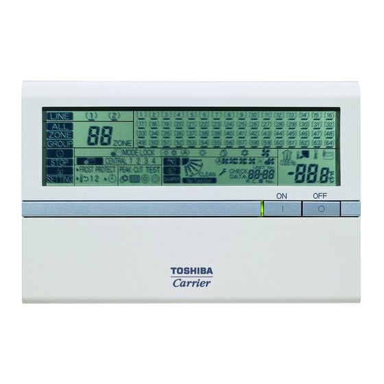
- Page 59 Engineering Book Smart Manager 8-1-2. Indications on the LCD panel ZONE GROUP , or is displayed. B: Line number When a line is selected, the ( ) mark of the selected line number flashes. The number lights up when any controllable unit is detected on the line.
- Page 60 Flashes for several minutes when the power switch is turned on. While this mark is flashing, no setting is enabled because the Smart Manager is recognizing connected groups. Lights while the controller prohibition function is activated. (While this mark is lighting, no operation is enabled.)
- Page 61 :Disables operation mode switching using the remote controller. CENTRAL “ ” is displayed for central or individual control other than above. STOP Press the OFF button to stop operation. * Indications on the LCD of the Smart Manager remain unchanged even when operation is stopped.
-
Page 62: Web Browser
Engineering Book Smart Manager 8-2. Web browser 8-2-1. Names and Functions of Main Screen Operating status and error status can be checked for all air conditioners. [List] screen Operation section Switches to the [List] screen Switches to the [Setup] screen... - Page 63 Engineering Book Smart Manager Air conditioners can be started or stopped, or their setup can be changed. In addition, the setup status, error details, and room temperature for each air condition can be checked. Operation section Warning List Switches to the [List] screen Current warnings are listed.
- Page 64 Engineering Book Smart Manager The Master schedule can be set or changed. [Weekly pattern] screen Operation section Switches to the [General] screen. Switches to the [Weekly pattern] screen. Switches to the [Special day] screen. Switches to the [Monthly schedule] screen.
- Page 65 Engineering Book Smart Manager 8-2-2. Log on / Log off [1] Log On [Log-on] screen Enter your user name. Enter your password. Left-click The screen will display [List] screen. NOTE Hereinafter, “left-click” will be referred to simply as “click” while “right-click will” be referred to as “right-click”.
- Page 66 Engineering Book Smart Manager 8-2-3. Creating a Master Schedule Operations of air conditioners can be scheduled. - The following can be set for scheduled operation. - On / Off, Operation mode, Temperature setup, Operation of remote control prohibited/allowed, Return Back, and Ventilation mode.
- Page 67 Engineering Book Smart Manager Weekly pattern setup [Weekly Pattern Setup screen] Click the tab to switch to the [Weekly pattern Setup] screen. Set the schedule operation start time, end time, and details according to the following steps. Setup steps a) Click the No. field of the day you wish to set.
- Page 68 Engineering Book Smart Manager [2] Changing a Master Schedule Place the cursor on to display the [Operation menu]. Click the Program Master Schedule in the [Operation menu]. The [Program Master Schedule] screen appears. To change the master schedule, click and...
- Page 69 Engineering Book Smart Manager Creating an Execution Schedule 1 REQUIREMENT Execution schedules can be created in either the [Setup] screen or the [List] screen. <Creating an Execution Schedule in the [List] screen [List] screen> [1] Creating an Execution Schedule for each Air Conditioner or Multiple...
- Page 70 Engineering Book Smart Manager Select the master schedule you wish to copy. To check the schedule details, click When the setup is completed, click The execution schedule is set for the air conditioner(s) selected. Creating an Execution Schedule 2 REQUIREMENT Execution schedules can be created in either the [Setup] screen or the [List] screen.
- Page 71 Engineering Book Smart Manager Click the Schedule field of the air [Set Master Schedule to Unit] conditioner that you wish to create the screen schedule for. To set in a batch, click The [Master Schedule] screen appears. Select the master schedule you wish to copy.
- Page 72 Engineering Book Smart Manager Checking / Changing an Execution Schedule 1 Reference: The execution schedules can be checked or changed with the same procedure as that used for creating the execution schedules. This can be done in either the [Setup] screen or the [List] screen.
- Page 73 Engineering Book Smart Manager Checking / Changing an Execution Schedule 2 <Checking/Changing an Execution [Setup] screen Schedule in the [Setup] screen> [1] Checking / changing an Execution Schedule for each Air Conditioner or Multiple Air Conditioners in a Batch Click to switch to the [Setup] screen.
- Page 74 Engineering Book Smart Manager 8-2-4. Warning List and History [ Alarm List ] : A list of current errors Lists the unit name, the time of occurrence of the error, and the error details. [Alarm History List] : Lists alarm history...
- Page 75 Engineering Book Smart Manager 8-2-5. User Account Setup System operation access can be assigned for each user. User names and passwords can also be set. * There are three levels of access. – Administrators - All operations are permitted. – Power Users - Some setup operations are permitted.
- Page 76 Engineering Book Smart Manager [2] Deleting a User Account Place the cursor on to display the [Operation menu]. Click the User Account in the [Operation menu] to display the [User Account] screen. Click and select the account that you wish to [User Account] screen delete in the [User Account] screen.
- Page 77 Engineering Book Smart Manager [4] Changing a User Account Level [User Account] screen [User Setting] screen Place the cursor on to display the [Operation menu]. Click the User Account in the [Operation menu] to display the [User Account] screen. Click and select the account for which you wish to change the level in the [User Account] screen.
- Page 78 Engineering Book Smart Manager 8-2-6. Other Settings [1] Support Information Display Click to display the [Contact] screen. The software version and support information is displayed on the screen. [2] Alarm Reset Place the cursor on the floor, tenant, area, or air conditioner in the tree format and right- click.
-
Page 79: Monthly Report
(referred to as “PC” hereafter) to arrange the indoor unit operation results that where tallied up by the Smart Manager in a report format. The software will also allow you to print these reports. • In addition to the monthly report, the Software supports four types of spreadsheets based on the monthly report, which can be output independently. - Page 80 Engineering Book Smart Manager • Window Image Creating a Billing Master Schedule If a billing schedule is set, the operation hours and power distribution can be calculated separately between office hours and after-hours. The billing schedule can be set using the same procedure as the schedule setup for scheduled operation.
- Page 81 Engineering Book Smart Manager [1] Creating a New Billing Master Schedule Place the cursor on to display the [Operation menu]. Click Program Billing Schedule in the [Operation menu]. The [Program Billing Schedule] screen appears. When creating a new billing master...
- Page 82 Engineering Book Smart Manager Special day setup [Special day Setup] screen The schedule is set for special days that are exceptions to the weekly pattern schedule. Click tab to switch to the [Special day Setup] screen. The schedule operation start time and end time can be set in the same way as the weekly pattern.
- Page 83 Engineering Book Smart Manager The schedule setup can be changed in the [Master Schedule Setup] screen same way as when creating a new billing master schedule (refer to page 81). [3] Copying a Billing Master schedule Place the cursor on to display the [Operation menu].
- Page 84 Engineering Book Smart Manager Creating a Billing Schedule 1 Reference: The billing schedule can be created in either the [Setup] screen or the [List] screen. <Creating a billing schedule in the [List] [List] screen screen> [1] Creating a Billing Schedule for...
- Page 85 Engineering Book Smart Manager Select the billing master schedule that you wish to copy. To check the schedule details, click When the setup is completed, click The billing schedule is set for the air conditioner(s) selected.
- Page 86 Engineering Book Smart Manager Creating a Billing Schedule 2 <Creating a Billing Schedule in the [Setup] [Setup] screen screen> [1] Creating a Billing Schedule for each Air conditioner or Multiple Air conditioners in Batch Click to switch to the [Setup] screen.
- Page 87 Engineering Book Smart Manager Power Meter Reading Date Setup / Change [1] Setting / Changing an Automatic Reading Date Place the cursor on to display the [Operation menu]. Click Automatic Meter-Reading in the [Operation menu] to display the [Automatic Meter-Reading] screen.
- Page 88 Engineering Book Smart Manager For temporary totaling: [Manual Meter-Reading] screen For temporary totaling, after the reading date, the operation time and power distribution aggregation values are continually counted. The period for totaling is displayed. Data from the previous reading date until the current date are totaled.
-
Page 89: Monthly Report Creation Procedure
This section describes the procedures for how to create a monthly report. 9-2-1. Downloading the Monthly Report Data File Download the monthly report data file and the daily report data file from the Web type Smart Manager by using the data download software. - Page 90 Engineering Book Smart Manager The download confirmation dialog box appears. Click [Yes] to download, or [No] to cancel the download. If the download is successful, the success message box appears.
-
Page 91: Creating The Monthly Report
Engineering Book Smart Manager 9-3. Creating the Monthly Report The following shows the procedure for creating the monthly report using the monthly report data file. Start the Software. Double-click the “Monthly report creation for SM” icon on the desktop or choose “Monthly report creation for SM”... - Page 92 Engineering Book Smart Manager To create a monthly report by using another monthly report data file, click [Change]. Select the target file in the displayed file selection dialog box, and click [Open]. The tally process starts. The window display content is updated during the file transfer. Wait for a while until the file transfer is completed.
- Page 93 Engineering Book Smart Manager...
-
Page 94: Creating The Specific Term Report
Then click [OK]. Or determine the range with the [This month] or [Last month] button, and the buttons in the “Year close setting” field. These buttons do not appear depending on the report creation term or the settings in the Smart Manager. - Page 95 Engineering Book Smart Manager Upon completion of the tally process, the specific term report window opens automatically. Click the appropriate buttons as the need arises. [Print] Click this button to print the created specific term reports. [Print by tenant] Click this button to print the created specific term reports (for all the units) by classifying them by tenant.
-
Page 96: 10Section Changeover Software
• Desktop icon Double-click the desktop icon. Fig.1 Section Changeover Software desktop icon • Windows menu Select [Start] > [All Programs] > [Toshiba] > [Section Changeover Software]. 2. The startup screen appears. The startup screen appears. Fig.2 Startup screen 3. Section Changeover Software Startup Complete The startup screen disappears, and the main screen appears. - Page 97 Engineering Book Smart Manager Downloading the Setting File Select the [File] menu > [Download], or click the [Download] icon on the toolbar. The Download Setting screen appears. To download the setting file for changing the zone names, follow the procedure below: Step 1 Select a system.
- Page 98 Engineering Book Smart Manager Changing the Zone Names The zone name tab screen consists of the Floor tab, Tenant tab, Area tab, and Monthly report tenant tab. Select the tab of the zone name you want to change, and enter a new name in the [After changing] column. The changed name is displayed in red.
- Page 99 Engineering Book Smart Manager Uploading the Edited Setting File Select the [File] menu > [Upload], or click the [Upload] icon on the toolbar. The Upload Setting screen appears. When the file has been loaded When the file has been loaded using “Download” or “Folder” and the upload screen appears, the upload folder is automatically selected.
- Page 100 Engineering Book Smart Manager When the upload starts, the upload confirmation dialog box appears. Fig.9 Upload confirmation dialog box Click [Yes] to upload. The upload execution screen appears (“Check for uploading is in progress.” -> “Uploading...”). To cancel the upload, click [No].
- Page 101 Engineering Book Smart Manager When the file has not been loaded When you open the upload screen without loading the file using “Download” or “Folder”, follow the procedure below to upload the file: Step 1 Click the [Browse] button of the upload folder, and select the destination folder to upload the setting file.
- Page 102 Engineering Book Smart Manager Using downloaded data as upload data When uploading, to use names in the downloaded data from the system instead of the uploaded data, clear the checkboxes in the comparison result list. If the checkboxes are cleared, the name of the downloaded data is applied to the actual uploaded data, and the data will be uploaded.
-
Page 103: 11Manual
Engineering Book Smart Manager Manual 11-1.Smart Manager 11-1-1.Install Manual 11-1-2.Owner’s Manual 11-1-3.Network Configuration Guide 11-1-4.WEB Type Owner’s Manual... -
Page 104: Monthly Report Creation Software
Engineering Book Smart Manager 11-2.Monthly Report Creation Software 11-2-1.Installation Manual 11-2-2.Operating Instructions 11-3.Data Download Software 11-3-1.Installation Manual 11-3-2.Operating Instructions... -
Page 105: Section Changeover Software
Engineering Book Smart Manager 11-4.Section Changeover Software 11-4-1.Installation Manual 11-4-2.Operating Instructions 11-5.Setting File Creation Software 11-5-1.Installation Manual 11-5-2.Operating Instructions...