Canon imageCLASS MF4890dw Service Manual
Hide thumbs
Also See for imageCLASS MF4890dw:
- Settings manual (120 pages) ,
- Basic operation manual (116 pages) ,
- Starter manual (60 pages)
Table of Contents
Advertisement
Quick Links
Advertisement
Table of Contents
Troubleshooting

Related Manuals for Canon imageCLASS MF4890dw


Summary of Contents for Canon imageCLASS MF4890dw
- Page 1 July 13, 2012 Revision 0 imageCLASS MF4890dw / MF4880dw / MF4770n imageCLASS D530 / FAXPHONE L190 Service Manual Product Overview Technical Overview Periodical Services Disassembly/Assembly Adjustment Troubleshooting Error Codes Service Mode Appendix...
- Page 2 This manual is copyrighted with all rights reserved. Under the copyright laws, this manual may changes in the contents of this manual over a long or short period, Canon will issue a new not be copied, reproduced or translated into another language, in whole or in part, without the edition of this manual.
- Page 3 Explanation of Symbols The following rules apply throughout this Service Manual: The following symbols are used throughout this Service Manual. 1. Each chapter contains sections explaining the purpose of specific functions and the relationship between electrical and mechanical systems with reference to the timing of Symbols Explanation Symbols...
-
Page 4: Table Of Contents
READER -------------------------------------------------------------------------------------1-13 Contents Printer -----------------------------------------------------------------------------------------1-13 Printer -----------------------------------------------------------------------------------------1-14 Control Panel ----------------------------------------------------------------------1-14 MF4890dw/MF4880dw/MF4830d/MF4820d ----------------------------------------1-14 MF4780w/MF4770n/MF4750/MF4730/MF4720/MF4712/MF4710 -----------1-16 Safety Precautions D530 ------------------------------------------------------------------------------------------1-17 CDRH Provisions -------------------------------------------------------------0-2 L418S/L410/L190 --------------------------------------------------------------------------1-18 Laser Safety --------------------------------------------------------------------0-2 2 Technical Overview About Laser Beams --------------------------------------------------------------- 0-2 Handling Laser Scanner Unit --------------------------------------------------- 0-2 Basic Configuration -----------------------------------------------------------2-2 Toner Safety --------------------------------------------------------------------0-3 Configuration function ------------------------------------------------------------ 2-2... - Page 5 Overview ------------------------------------------------------------------------------------- 2-11 Overview -------------------------------------------------------------------------------------2-22 Controlling the Laser Activation Timing --------------------------------------2-12 Main Parts of Fixing assembly ---------------------------------------------------------2-22 Various Control Mechanisms --------------------------------------------------2-23 Laser ON/OFF Control -------------------------------------------------------------------2-12 Horizontal Sync Control ------------------------------------------------------------------2-12 Fixing Temperature Control -------------------------------------------------------------2-23 Laser Control -----------------------------------------------------------------------2-13 Protective Functions ----------------------------------------------------------------------2-23 Other Functions -------------------------------------------------------------------2-24 Auto Power Control (APC) --------------------------------------------------------------2-13 Laser Scanner Motor Control --------------------------------------------------2-13 Throughput Down Control ---------------------------------------------------------------2-24...
- Page 6 Consumables ----------------------------------------------------------------------- 3-2 Preparation ----------------------------------------------------------------------------------4-18 Procedure ------------------------------------------------------------------------------------4-18 Periodical Service -------------------------------------------------------------3-3 Removing the Upper Cover(MF4890dw/4880dw) ------------------------4-18 Scheduled Servicing -------------------------------------------------------------- 3-3 Preparation ----------------------------------------------------------------------------------4-18 Cleaning -------------------------------------------------------------------------3-3 Procedure ------------------------------------------------------------------------------------4-18 Printer --------------------------------------------------------------------------------- 3-3 Removing the Left Cover(MF4870dn/MF4830d)--------------------------4-20 Reader ADF ------------------------------------------------------------------------- 3-4 Procedure ------------------------------------------------------------------------------------4-20 SADF ------------------------------------------------------------------------------------------ 3-4 Removing the Right Cover(MF4870dn/MF4830d)------------------------4-21 DADF ------------------------------------------------------------------------------------------ 3-4 Procedure ------------------------------------------------------------------------------------4-21...
- Page 7 Removing the Right Cover(MF4780w/MF4770n/MF4750/MF4730) -4-33 Preparation ----------------------------------------------------------------------------------4-47 Procedure ------------------------------------------------------------------------------------4-47 Procedure ------------------------------------------------------------------------------------4-33 Removing the DADF Motor Unit (MF4890dw/MF4880dw) -------------4-50 Removing the Front Cover Unit(MF4780w/MF4770n/MF4750/MF4730) - Preparation ----------------------------------------------------------------------------------4-50 4-34 Procedure ------------------------------------------------------------------------------------4-50 Preparation ----------------------------------------------------------------------------------4-34 Removing the DADF Solenoid Unit (MF4890dw/MF4880dw) ---------4-51 Procedure ------------------------------------------------------------------------------------4-34 Preparation ----------------------------------------------------------------------------------4-51 Removing the Upper Cover MF4780w/MF4770n/MF4750/MF4730) 4-34 Procedure ------------------------------------------------------------------------------------4-51...
- Page 8 Removing the SADF Separation Pad(MF4870dn/MF4830d) ----------4-71 Preparation ----------------------------------------------------------------------------------4-90 Procedure ------------------------------------------------------------------------------------4-90 Preparation ----------------------------------------------------------------------------------4-71 Removing the SADF Unit and Reader Unit(MF4780w/MF4770n/ Procedure ------------------------------------------------------------------------------------4-71 Removing the Copyboard Glass(MF4870dn/MF4830d) ----------------4-74 MF4750/MF4730) -----------------------------------------------------------------4-92 Preparation ----------------------------------------------------------------------------------4-74 Preparation ----------------------------------------------------------------------------------4-92 Procedure ------------------------------------------------------------------------------------4-74 Procedure ------------------------------------------------------------------------------------4-92 Removing the Flatbed Motor Unit(MF4870dn/MF4830d) ---------------4-75 Removing the SADF Unit (MF4780w/MF4770n/MF4750/MF4730) --4-93 Preparation ----------------------------------------------------------------------------------4-75 Preparation ----------------------------------------------------------------------------------4-93...
- Page 9 Removing the Copyboard Cover (MF4720w/MF4712/MF4710) ---- 4-109 Preparation -------------------------------------------------------------------------------- 4-128 Procedure ---------------------------------------------------------------------------------- 4-128 Procedure ---------------------------------------------------------------------------------- 4-109 Removing the Flatbed Motor Unit (L418S/L410/L190) ---------------- 4-130 Removing the Copyboard Cover and Reader Unit (MF4720w/MF4712/ Preparation -------------------------------------------------------------------------------- 4-130 MF4710) --------------------------------------------------------------------------- 4-109 Procedure ---------------------------------------------------------------------------------- 4-130 Preparation -------------------------------------------------------------------------------- 4-109 Removing the DADF CIS Unit (L418S/L410/L190)--------------------- 4-132 Procedure ---------------------------------------------------------------------------------- 4-109...
- Page 10 MF4880dw) ----------------------------------------------------------------------- 4-149 Procedure ---------------------------------------------------------------------------------- 4-169 Removing the Toner Sensor and Multi Pickup Sensor Unit (MF4870dn) - Preparation -------------------------------------------------------------------------------- 4-149 4-172 Procedure ---------------------------------------------------------------------------------- 4-149 Removing the Toner Sensor and Multi Pickup Sensor Unit (MF4890dw/ Preparation -------------------------------------------------------------------------------- 4-172 MF4880dw) ----------------------------------------------------------------------- 4-151 Procedure ---------------------------------------------------------------------------------- 4-172 Removing the Speaker (MF4870dn) --------------------------------------- 4-174 Preparation -------------------------------------------------------------------------------- 4-151...
- Page 11 Preparation -------------------------------------------------------------------------------- 4-192 Removing the FAX NCU PCB (MF4780w/MF4770n/MF4750/) ----- 4-221 Procedure ---------------------------------------------------------------------------------- 4-192 Preparation -------------------------------------------------------------------------------- 4-221 Removing the Main Motor (D530) ------------------------------------------ 4-195 Procedure ---------------------------------------------------------------------------------- 4-221 Preparation -------------------------------------------------------------------------------- 4-195 Removing the Wireless LAN PCB (MF4780w) -------------------------- 4-221 Procedure ---------------------------------------------------------------------------------- 4-195 Preparation -------------------------------------------------------------------------------- 4-221 Removing the Main Fan (D530) --------------------------------------------- 4-199 Procedure ---------------------------------------------------------------------------------- 4-221...
- Page 12 MF4712/MF4710) --------------------------------------------------------------- 4-241 Preparation -------------------------------------------------------------------------------- 4-262 Procedure ---------------------------------------------------------------------------------- 4-262 Preparation -------------------------------------------------------------------------------- 4-241 Removing the Toner Sensor and Multi Pickup Sensor Unit (L418S/ Procedure ---------------------------------------------------------------------------------- 4-241 Removing the Toner Sensor and Multi Pickup Sensor Unit (MF4720w/ L410/L190) ----------------------------------------------------------------------- 4-265 MF4712/MF4710) --------------------------------------------------------------- 4-244 Preparation -------------------------------------------------------------------------------- 4-265 Procedure ---------------------------------------------------------------------------------- 4-265 Preparation -------------------------------------------------------------------------------- 4-244...
- Page 13 Removing the Transfer Roller (MF4820d) -------------------------------- 4-283 Procedure ---------------------------------------------------------------------------------- 4-311 Removing the Pickup Tray Unit (MF4890dw/MF4880dw) ------------ 4-314 Procedure ---------------------------------------------------------------------------------- 4-283 Removing the Transfer Roller (D530) -------------------------------------- 4-284 Preparation -------------------------------------------------------------------------------- 4-314 Procedure ---------------------------------------------------------------------------------- 4-314 Procedure ---------------------------------------------------------------------------------- 4-284 Removing the Pickup Roller (MF4890dw/MF4880dw) ---------------- 4-316 Removing the Transfer Roller (MF4780w/MF4770n/MF4750/MF4730) -- Preparation -------------------------------------------------------------------------------- 4-316 4-285...
- Page 14 Preparation -------------------------------------------------------------------------------- 4-336 Procedure ---------------------------------------------------------------------------------- 4-359 Procedure ---------------------------------------------------------------------------------- 4-336 Removing the Pickup Unit (MF4780w/MF4770n/MF4750/MF4730) ------- Removing the Pickup Tray Unit (MF4820d) ------------------------------ 4-339 4-362 Preparation -------------------------------------------------------------------------------- 4-339 Preparation -------------------------------------------------------------------------------- 4-362 Procedure ---------------------------------------------------------------------------------- 4-339 Procedure ---------------------------------------------------------------------------------- 4-362 Removing the Pickup Roller (MF4820d) ---------------------------------- 4-341 Removing the Pickup Tray Unit (MF4780w/MF4770n/MF4750/MF4730) Preparation -------------------------------------------------------------------------------- 4-341 4-365...
- Page 15 Removing the Pickup Tray Unit (L418S/L410/L190) ------------------- 4-383 What to Prepare ----------------------------------------------------------------------------- 6-7 Operation Procedure----------------------------------------------------------------------- 6-7 Preparation -------------------------------------------------------------------------------- 4-383 Troubleshooting ----------------------------------------------------------------------------- 6-8 Procedure ---------------------------------------------------------------------------------- 4-383 Removing the Pickup Roller (L418S/L410/L190) ----------------------- 4-385 7 Error Codes Preparation -------------------------------------------------------------------------------- 4-385 Procedure ---------------------------------------------------------------------------------- 4-385 Overview ------------------------------------------------------------------------7-2 Removing the Pickup Solenoid (L418S/L410/L190) ------------------- 4-386 Error Codes ---------------------------------------------------------------------7-3...
- Page 16 Service Tools -------------------------------------------------------------------9-2 JAM -------------------------------------------------------------------------------------------- 8-7 FEEDER -------------------------------------------------------------------------8-8 Solvent/Oil List -----------------------------------------------------------------9-3 ADJUST ------------------------------------------------------------------------------ 8-8 General Circuit Diagram -----------------------------------------------------9-4 FUNCTION -------------------------------------------------------------------------- 8-8 MF4890dw/MF4880dw/MF4870dn ----------------------------------------------------- 9-4 FAX -------------------------------------------------------------------------------8-9 MF4830d/MF4820d ------------------------------------------------------------------------ 9-5 MF4780w/MF4770n/MF4750 ------------------------------------------------------------ 9-6 List of SSSW ------------------------------------------------------------------------ 8-9 MF4730 --------------------------------------------------------------------------------------- 9-7 List of Menu ------------------------------------------------------------------------8-10 MF4720w/MF4712/MF4710-------------------------------------------------------------- 9-8 List of NUM ------------------------------------------------------------------------- 8-11...
-
Page 17: Safety Precautions
Safety Precautions ■ CDRH Provisions ■ Laser Safety ■ Toner Safety ■ Notes on Handling Lithium Battery ■ Notes on Assembly/ Disassembly... -
Page 18: Cdrh Provisions
Safety Precautions > Laser Safety > Handling Laser Scanner Unit CDRH Provisions Laser Safety Food and Drug CDRH (Center for Devices and Radiological Health) under FDA (Food and About Laser Beams Drug Administration) enforced provisions of the section for laser and laser products on August 2, 1976. -
Page 19: Toner Safety
Safety Precautions > Notes on Assembly/Disassembly Toner Safety Notes on Assembly/Disassembly Follow the items below to assemble/disassemble the device. About Toner 1. Disconnect the power plug to avoid any potential dangers during assembling/disassembling works. Toner is a nontoxic matter composed of plastic, iron and a trace of pigments. 2. -
Page 20: Product Overview
Product Overview ■ Product Lineups ■ Features ■ Product Specifications ■ Name of Parts Product Overview... -
Page 21: Main Unit
Product Overview > Product Lineups > Main Unit Product Lineups Model MF4820d Config 3in1 PLATEN Main Unit Model MF4890dw MF4880dw MF4870dn MF4830d Config 4in1 DADF+WN 4in1 SADF+WN 4in1 SADF+N 3in1 SADF Design Design DADF SADF PLATEN 2-Sided Engine 1-Sided LAN port DADF Wireless LAN SADF... -
Page 22: Options
Product Overview > Product Lineups > Options Options MF4780w/MF4770n/MF4750/ Model D530 MF4730 • Hand Set Only FAX Model DADF SADF PLATEN 2-Sided Engine 1-Sided LAN port Yes( MF4780w/MF4770n/MF4750) Wireless LAN Yes( MF4780w) MF4780w/MF4770n/MF4750) Yes( T-1-3 Model MF4720w/MF4712/MF4710 L418S/L410/L190 Config 3in1 PLATEN 4in1 DADF Design DADF... -
Page 23: Features
Product Overview > Product Specifications > Main Unit Specifications Features Product Specifications Features Main Unit Specifications 1. Small-size, high-speed monochrome printer Copyboard Fixed This equipment has a compact body that realizes high-speed print of 25 ppm (A4) / 26 ppm Device Installation Desktop Light source... - Page 24 Product Overview > Product Specifications > Main Unit Specifications Print Speed MF4890dw/MF4880dw/MF4870dn/MF4830d/MF4820d/D530/ Maximum power consumption MF4890dw/MF4880dw/MF4870dn/MF4830d/MF4820d/MF4780w/ L418S/L410/L190 MF4770n/MF4750/MF4730/MF4720w/MF4712/MF4710 120 V model : 1110 W or less 25 ppm (A4) 230 V model : 1320W or less MF4780w/MF4770n/MF4750/MF4730/MF4720w/MF4712/MF4710 D530/L418S/L410/L190 23 ppm (A4) 120 V model : 1110 W or less Copy speed MF4890dw/MF4880dw/MF4870dn/MF4830d/MF4820d/D530/...
-
Page 25: Wireless Lan Specifications
Product Overview > Product Specifications > FAX Specifications Wireless LAN Specifications FAX Specifications (MF4890dw/MF4880dw/MF4870dn/MF4780w/MF4770n/MF4750) Standard IEEE802.11g/IEEE802.11b/IEEE 802.11n* Transmission Scheme DS-SS System/OFDM System Line Used Public Switched Telephone Network (PSTN)*1 Frequency Range 2412 to 2472 MHz Communication Mode Super G3, G3 Data Transmission •... -
Page 26: Name Of Parts
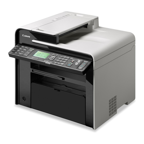
Product Overview > Name of Parts > External View > MF4890dw/MF4880dw Name of Parts (L418S/L410/L190) Line Used Public Switched Telephone Network (PSTN)*1 Communication Mode Super G3, G3 External View Compression Method MH, MR, MMR Modem Speed Super G3: 33.6 Kbps, G3: 14.4 Kbps ■... -
Page 27: Mf4870Dn/Mf4830D/Mf4780W/Mf4770N/Mf4750/Mf4730
Product Overview > Name of Parts > External View > MF4870dn/MF4830d/MF4780w/MF4770n/MF4750/MF4730 ■ MF4870dn/MF4830d/MF4780w/MF4770n/MF4750/MF4730 Name Name [10] Multi-Purpose Tray [23] Power Switch ● Front Side [11] Tray Cover [24] Front Cover Switch [12] Pickup Tray Paper Guides [25] Copyboard Upper Cover [13] Trailing Edge Paper Guides [2] [3]... -
Page 28: Mf4820D/Mf4720W/Mf4712/Mf4710
Product Overview > Name of Parts > External View > MF4820d/MF4720w/MF4712/MF4710 ● Rear Side ■ MF4820d/MF4720w/MF4712/MF4710 ● Front Side [11] HA ND SE T EX T. HAND EXT. LINE [17] LIN E F-1-4 Name [10] [16] USB Device Port LAN Port [15] External Device Jack [13]... -
Page 29: D530
Product Overview > Name of Parts > External View > D530 1-10 ● Rear Side ■ D530 ● Front Side [10] HA ND SE T EX T. HAND EXT. LINE [16] LIN E F-1-6 Name USB Device Port [15] [11] Power Supply Cord Slot Rear Cover [14]... -
Page 30: L418S/L410/L190
Product Overview > Name of Parts > External View > L418S/L410/L190 1-11 ● Rear Side ■ L418S/L410/L190 ● Front Side [16] [15] HA ND SE T EX T. HAND EXT. [22] LINE [14] LIN E F-1-8 [13] [21] [17] Name USB Device Port [20] Power Supply Cord Slot... -
Page 31: Cross Section
Product Overview > Name of Parts > Cross Section > SADF 1-12 Cross Section Rear Side ■ DADF HA ND SE T EX T. HAND EXT. LINE LIN E F-1-11 F-1-10 Name Registration roller Pickup roller Name Separation pad USB Device Port Delivery roller LAN Port Separation roller... -
Page 32: Reader
Product Overview > Name of Parts > Cross Section > Printer 1-13 ■ READER ■ Printer ● MF4890dw/MF4880dw/MF4870dn/MF4830d/MF4820/D530/L418S/ L410/L190 F-1-13 Name CIS UNIT [14] [13] [12] [11] [10] F-1-14 Name Name Duplex Feed Unit Pickup Tray Duplex Feed Roller Multi-Purpose Tray Fixing Pressure Roller [10] Photosensitive Drum... -
Page 33: Control Panel
Product Overview > Name of Parts > Control Panel > MF4890dw/MF4880dw/MF4830d/MF4820d 1-14 Control Panel ■ Printer ● MF4780w/MF4770n/MF4750/MF4730/MF4720w/MF4712/MF4710 ■ MF4890dw/MF4880dw/MF4830d/MF4820d F-1-16 [12] [11] [10] F-1-15 Name Name Fixing Pressure Roller Multi-Purpose Tray Fixing Film Unit Photosensitive Drum Delivery Roller Pickup Roller Fixing Assembly [10] Separation Pad... - Page 34 Product Overview > Name of Parts > Control Panel > MF4890dw/MF4880dw/MF4830d/MF4820d 1-15 Press to send the scanned documents to the registered (1) Mode switching keys Press to switch the mode to copy, fax, or scan [Scan>PC1] key/ computer for each key. (2) [One-touch Speed Dial] keys Press to select destinations registered in one-touch keys.
-
Page 35: Mf4780W/Mf4770N/Mf4750/Mf4730/Mf4720/Mf4712/Mf4710
Product Overview > Name of Parts > Control Panel > MF4780w/MF4770n/MF4750/MF4730/MF4720/MF4712/MF4710 1-16 ■ MF4780w/MF4770n/MF4750/MF4730/MF4720/MF4712/ (1) Mode switching keys Press to switch the mode to copy, fax, or scan (2) [One-touch Speed Dial] keys Press to select destinations registered in one-touch keys. MF4710 [Address Book] key Press to search for recipients who are registered under one-... - Page 36 Product Overview > Name of Parts > Control Panel > D530 1-17 ■ D530 Press to send the scanned documents to the registered [Scan>PC1] key/ computer for each key. [Scan>PC2] key "[Scan>PC1] key/[Scan>PC2] key" Press to copy with a preset setting to save paper. [Paper Save Copy] key "[Paper Save Copy] key"...
-
Page 37: L418S/L410/L190
Product Overview > Name of Parts > Control Panel > L418S/L410/L190 1-18 ■ L418S/L410/L190 (1) Mode switching keys Press to switch the mode to copy or scan. (2) [N on 1] key Press to select the setting for printing multiple documents onto one sheet. - Page 38 Product Overview > Name of Parts > Control Panel > L418S/L410/L190 1-19 (1) [FAX/COPY] key Press to switch the mode to copy or fax. (2) LCD During normal operation, displays messages and prompts. When adjusting the settings, displays your selections, text, and numbers.
-
Page 39: Technical Overview
Technical Overview ■ Basic Configuration ■ Controller System ■ Document Exposure/Feeder System ■ Laser Exposure System ■ Image Formation System ■ Fixing System ■ Pickup And Feeding System ■ External And Controls System Technical Overview... -
Page 40: Configuration Function
Technical Overview > Basic Configuration > Basic Sequence > Basic Sequence of Operation Basic Configuration Basic Sequence ■ Basic Sequence of Operation Configuration function The engine controller controls the operation sequence. The following table provides an outline The machine may be broadly divided into the following 7 functional blocks: engine control of machine operation occurring from when the power switch is turned on to when printing system, document exposure/feeding system, laser exposure system, image formation system, ends and motors stop, indicating the purposes of intervals and engine operation. -
Page 41: Print Sequence
Technical Overview > Basic Configuration > Basic Sequence > Print Sequence Print Sequence ■ Power-on (Unit:Seconds) WAIT STBY INTR PRINT LSTR STBY Sequence Controls at 80 C Print temperature control Fixing heater Relay Waiting for Print command Print command Print command a print command Scanner motor BD emission/... -
Page 42: Controller System
Technical Overview > Controller System > Engine Controller > General description Controller System Engine Controller ■ General description Main Controller Engine controller is the circuit to control the operation sequence of the host machine and it is ■ General description controlled by the CPU inside the engine controller. -
Page 43: Service Works
Technical Overview > Controller System > Service Works > Notes on service works Service Works ■ At parts replacement No work is required for this product at parts replacement. ■ Maintenance No periodically replaced parts, durable parts or periodical service is set for this product. ■... -
Page 44: Document Exposure/Feeder System
Technical Overview > Document Exposure/Feeder System > Document Exposure System > Major Components Document Exposure/Feeder System ■ Major Components Followings are the major components for Document Exposure System. Document Exposure System • The contact sensor to scan document • The Reader motor, the drive pulley, the drive belt, to shift the contact sensor ■... -
Page 45: Document Feeder System
Technical Overview > Document Exposure/Feeder System > Document Feeder System > Overview Document Feeder System ● DADF Pickup/Feed/Delivery Operation ■ Overview The Double-side Auto Document Feeder (DADF) mounted onto this host machine is dedicated to stream-reading. ● SADF 1 motor (DADF motor) is engaged in pickup/feeding/delivery. The Single-side Auto Document Feeder (SADF) mounted onto this host machine is dedicated At the start of copy/fax/scan, the DADF motor is driven by the drive command from the Main to stream-reading. -
Page 46: Various Control
Technical Overview > Document Exposure/Feeder System > Document Feeder System > Various Control • Reverse to Reading of the 2nd side ■ Various Control ● Original Detection There are two types of original detection in this equipment. 1. Original Presence / Absence Detection Detected by DS (Document Sensor) As the actuator is pushed up by placing an original on the Original Tray, DS of SADF is turned ON(light is blocked =>light is transmitted) and DS of DADF is turned OFF (light is... - Page 47 Technical Overview > Document Exposure/Feeder System > Document Feeder System > Various Control In the case of SADF ● Jam Detection Document The following cases are judged as jam. Sensor 1. In case of delay in reaching DS/DES or stationary during scanning of original 2.
-
Page 48: Service Works
Technical Overview > Document Exposure/Feeder System > Service Works > Notes on service works 2-10 Service Works ■ At parts replacement No work is required for this product at parts replacement. ■ Maintenance No periodically replaced parts, durable parts or periodical service is set for this product. ■... -
Page 49: Laser Exposure System
Technical Overview > Laser Exposure System > Overview > Overview 2-11 Laser Exposure System The operational sequence of the laser scanner unit is described below. 1) When the Main controller sends print instruction command, the Engine controller rotates the Four-faced mirror, causing the Scanner motor to rotate. Overview 2) When the Scanner motor starts to rotate, the Engine controller emits the laser forcibly ■... -
Page 50: Controlling The Laser Activation Timing
Technical Overview > Laser Exposure System > Controlling the Laser Activation Timing > Horizontal Sync Control 2-12 Controlling the Laser Activation Timing The engine controller sends the laser control signals (CNT0, CNT1, CNT2) for changing the operation mode of the laser to the logic circuit in the laser driver IC, as well as the video ■... -
Page 51: Laser Control
Technical Overview > Laser Exposure System > Laser Scanner Motor Control > Overview 2-13 Laser Control Laser Scanner Motor Control ■ Auto Power Control (APC) ■ Overview This is the control to emit a constant level of laser diode. This is the control to rotate the scanner motor at a constant speed to emit the laser beam on There are two types of APC;... -
Page 52: Scanner Motor Fault Detection
Technical Overview > Laser Exposure System > Service Works > Notes on service works 2-14 ■ Scanner Motor Fault Detection This is the detection of faults in the laser scanner unit. When the laser scanner unit falls into either of the following status, the engine controller judges it as a fault in the laser scanner unit system and notices the status of fault to the main controller. -
Page 53: Image Formation System
Technical Overview > Image Formation System > Overview/Configuration > Print Process 2-15 Image Formation System ■ Print Process This explains the basic process of the operations that a printer executes for image formation. Overview/Configuration The print process of this equipment is divided largely into 5 blocks, 7 steps. Toner images are formed on papers by executing the steps of each block in order. -
Page 54: Static Latent Image Formation Block
Technical Overview > Image Formation System > Overview/Configuration > Static Latent Image Formation Block 2-16 ■ Static Latent Image Formation Block Step 2: Laser beam exposure In this step, static latent images are formed on the photosensitive drum with laser beam. This block is comprised of two steps and forms static latent images on the photosensitive When laser beams are scanned on the photosensitive drum negatively charged, bright areas drum. -
Page 55: Development Block
Technical Overview > Image Formation System > Overview/Configuration > Transfer Block 2-17 ■ Development Block ■ Transfer Block This block is comprised of one step; it puts toners to the static latent images on the surface of This block is comprised of two steps; it transfers toner images on the surface of the the photosensitive drum and visualizes the images using toner projection development. -
Page 56: Fixing Block
Technical Overview > Image Formation System > Overview/Configuration > Drum Cleaning Block 2-18 Step 5: Separation ■ Drum Cleaning Block In this step, DC negative bias is applied to the static eliminator according to the elasticity of The drum cleaning block removes the toner remained on the photosensitive drum. papers to separate the papers from the photosensitive drum. -
Page 57: High-Voltage Control
Technical Overview > Image Formation System > High-Voltage Control > Generating Transfer Bias 2-19 High-Voltage Control ■ Generating Developing Bias The developing bias is a DC negative bias that is output to affix toner to the static latent ■ Overview images formed on the photosensitive drum. -
Page 58: Toner Cartridge
Technical Overview > Image Formation System > Toner Cartridge > Operation when toner level is Low/Nearly Out 2-20 Toner Cartridge ■ Specification of Toner level display Toner level can be checked by pressing Status Monitor/Cancel key and selecting toner level. ■... -
Page 59: Toner Cartridge Absence/Presence Detection
Technical Overview > Image Formation System > Service Works > Notes on service works 2-21 ■ Toner Cartridge Absence/Presence Detection If jam occurs when ‘Toner cartridge absent’ is detected, check if there is a fault in the leading edge sensor and the detection flag. The engine controller detects the position of the Toner cartridge detection flag to judge the absence/presence of the Toner cartridge. -
Page 60: Fixing System
Technical Overview > Fixing System > Overview/Configuration > Main Parts of Fixing assembly 2-22 Fixing System ■ Main Parts of Fixing assembly Engine controller Overview/Configuration Fixing control FIXING HEATER ■ Overview DRIVE signal Fixing/delivery system consists of the fixing film unit, pressure roller and delivery roller etc. Fixing heater These rollers are driven by the main motor (M1). -
Page 61: Various Control Mechanisms
Technical Overview > Fixing System > Various Control Mechanisms > Protective Functions 2-23 Various Control Mechanisms There are 11 types of target fixing temperature depending on the fixing mode. These types are according to the paper type settings and resolution settings on a driver. ■... -
Page 62: Other Functions
Technical Overview > Fixing System > Other Functions > Throughput Down Control 2-24 by monitoring the temperature for every 5 msec, it is judged as Thermistor short circuit Other Functions failure. In addition, this function also doubles as abnormal high temperature detection ■... -
Page 63: Service Works
Technical Overview > Fixing System > Service Works > Notes on service works 2-25 Number of Fed Sheets Half speed Half speed Half speed Half speed ー 1 to 2 11 ppm 12 ppm 7 ppm 9 ppm 12 ppm ー... -
Page 64: Pickup And Feeding System
Technical Overview > Pickup And Feeding System > Overview > Overview 2-26 Pickup And Feeding System Overview ■ Overview Duplex Feed Single Feed Main controller Main controller Engine controller Engine controller Fixing Delivery roller Pressure PS702 PS702 Delivery roller roller Fixing Pressure roller... -
Page 65: Detecting Jams
Technical Overview > Pickup And Feeding System > Detecting Jams > Jam Detection Outline 2-27 Detecting Jams The pickup and feeding system executes pickup and feeding of papers and is composed of the main motor, solenoid, and rollers. ■ Jam Detection Outline In this equipment, pickup from the pickup tray and manual feed tray is available. -
Page 66: Delay Jams
Technical Overview > Pickup And Feeding System > Detecting Jams > Delay Jams 2-28 ■ Delay Jams B. When there is a preceding paper 1 ● Delivery Delay Jam Paper Lead Edge Sensor There are 3 types of delivery delay jam detections as follows: A. -
Page 67: Reversal Delay Jam
Technical Overview > Pickup And Feeding System > Reversal Delay Jam 2-29 Reversal Delay Jam ● Delivery Delay during cleaning A delivery delay jam is determined if the Fixing Delivery Sensor (PS701) fails to detect A reversal delay jam is determined when the Fixing Delivery Sensor (PS701) detects absence presence of paper within 1235 msec since the Paper Lead Edge Sensor (PS751) detected of paper at the time of 440 msec elapsed after the start of reversal operation. -
Page 68: Stationary Jams
Technical Overview > Pickup And Feeding System > Reversal Delay Jam > Stationary Jams 2-30 ■ Stationary Jams ● Pickup Stationary Jam during auto delivery A pickup stationary jam is determined if the Paper Lead Edge Sensor (PS751) detects ● Pickup Stationary Jam presence of paper at the time of 1115 msec elapsed after the start of auto delivery and then Without pre-feed, a feed stationary jam is determined if the TOP sensor (PS751) cannot the Paper Lead Edge Sensor (PS751) detects presence of paper after the paper continued to... -
Page 69: Other Jams
Technical Overview > Pickup And Feeding System > Reversal Delay Jam > Other Jams 2-31 ■ Other Jams ● No-paper detection during cleaning ● Fixing Wrap Jam Solenoid Paper Lead Edge 1370 Sensor Paper Lead Edge Sensor Fixing Delivery paper detection Sensor period (110) -
Page 70: Service Works
Technical Overview > Pickup And Feeding System > Service Works > Notes on service works 2-32 Service Works ■ At parts replacement No work is required for this product at parts replacement. ■ Maintenance No periodically replaced parts, durable parts or periodical service is set for this product. ■... -
Page 71: External And Controls System
Technical Overview > External And Controls System > Power Supply > Protective Functions 2-33 External And Controls System ■ Protective Functions ● Power protective function Power Supply Low voltage power circuit carries the overcurrent preventive function against and overvoltage preventive function that block the voltage output automatically to prevent the power circuit ■... -
Page 72: Service Works
Technical Overview > External And Controls System > Service Works > Notes on service works 2-34 Service Works ■ At parts replacement No work is required for this product at parts replacement. ■ Maintenance No periodically replaced parts, durable parts or periodical service is set for this product. ■... -
Page 73: Periodical Services
Periodical Services ■ Periodically Replaced Parts ■ Consumables ■ Periodical Service ■ Cleaning Periodical Services... -
Page 74: Consumables
Periodical Services > Consumables > Consumables Periodically Replaced Parts Consumables Periodically Replaced Parts Consumables There is no periodically replaced part with this machine. There is no consumable with this machine. Periodical Services > Consumables > Consumables... -
Page 75: Periodical Service
Periodical Services > Cleaning > Printer Periodical Service Cleaning Scheduled Servicing Printer There is no portion that requires schedule servicing in this equipment. [7] [8] F-3-1 Cleaning parts Procedure Duplex Feed Roller Clean it with a dry lint-free paper. Fixing inlet guide Clean it with a dry lint-free paper. -
Page 76: Reader Adf
Periodical Services > Cleaning > Reader ADF > DADF Reader ADF ■ DADF ■ SADF F-3-3 Cleaning parts Procedure DADF Pickup Roller Unit Open the ADF and wipe off the smudge with the soft dry cloth. F-3-2 DADF Separation Pad Open the ADF and wipe off the smudge with the soft dry cloth. -
Page 77: Disassembly/Assembly
Disassembly/Assembly ■ List of Parts ■ List of Connectors ■ External Cover, Interior ■ Document Exposure/Feeder System ■ Controller System ■ Laser Exposure System ■ Image Formation System ■ Fixing System ■ Pickup And Feeding System Disassembly/Assembly... - Page 78 Disassembly/Assembly > Outline Outline This chapter describes disassembling/assembling procedure of this equipment. The service technician is to identify the cause of the failures according to "Chapter 6 Troubleshooting" and to replace the faulty parts by following the disassembling procedure. In addition, replace the consumable parts by following the same disassembling procedure.
-
Page 79: Main Unit
Disassembly/Assembly > List of Parts > Main Unit > Lists of SADF Unit List of Parts Main Unit ■ Lists of SADF Unit ■ Lists of DADF Unit F-4-2 Name Reference Remarks F-4-1 Name Reference Remarks Original Sensor Original Sensor Original Edge Sensor DADF Motor SADF Motor... -
Page 80: Lists Of Reader Unit
Disassembly/Assembly > List of Parts > Duplex Printer Unit > Lists of Motor/Fan Duplex Printer Unit ■ Lists of Reader Unit ■ Lists of Motor/Fan F-4-3 Name Reference Remarks CIS Sensor Reader Motor F-4-4 Name Reference Remarks Main Motor Main Fan Unit Laser Scanner Unit Disassembly/Assembly >... -
Page 81: Lists Of Solenoid
Disassembly/Assembly > List of Parts > Duplex Printer Unit > List of Sensor ■ Lists of Solenoid ■ List of Sensor F-4-5 Name Reference Remarks F-4-6 Duplex Solenoid Name Reference Remarks Pickup Solenoid Encoder Sensor Multi Pickup Sensor Toner Sensor Paper Leading Edge Sensor Paper Width Sensor... -
Page 82: List Of Switch And Speaker
Disassembly/Assembly > List of Parts > Duplex Printer Unit > List of Heater/Thermoswitch/Thermistor ■ List of Switch and Speaker ■ List of Heater/Thermoswitch/Thermistor F-4-8 F-4-7 Name Reference Remarks Name Reference Remarks Thermoswitch [1] Speaker Fixing Heater [2] Power Switch Thermistor [3] Speaker L418S/L410/L190 [4] Door Switch... -
Page 83: List Of Pcb
Disassembly/Assembly > List of Parts > Single-sided Printer Unit > List of Motor/Fan Single-sided Printer Unit ■ List of PCB ■ List of Motor/Fan [12] [11] [10] F-4-10 Name Reference Remarks F-4-9 Main Motor Name Reference Remarks Laser Scanner Motor Control Panel PCB Duplex Driver PCB Motor Driver PCB... -
Page 84: List Of Solenoid
Disassembly/Assembly > List of Parts > Single-sided Printer Unit > List of Solenoid ■ List of Solenoid ● List of Sensor F-4-11 F-4-12 Name Reference Remarks Name Reference Remarks Pickup Solenoid Encoder Sensor Multi Pickup Sensor Toner Sensor Paper Leading Edge Sensor Paper Width Sensor Fixing Delivery Sensor Disassembly/Assembly >... - Page 85 Disassembly/Assembly > List of Parts > Single-sided Printer Unit > List of Solenoid ● List of Switch and Speaker ● List of Heater/Thermoswitch/Thermistor F-4-14 F-4-13 Name Reference Remarks Name Reference Remarks Thermoswitch [1] Speaker Fixing Heater [2] Power Switch Thermistor [3] Door switch Disassembly/Assembly >...
- Page 86 Disassembly/Assembly > List of Parts > Single-sided Printer Unit > List of Solenoid 4-10 ● List of PCB [11] [10] F-4-15 Name Reference Remarks Control Panel PCB Motor Driver PCB Laser Driver PCB WiFi Module PCB Switch PCB Off Hook PCB 100V Model Only FAX-NCU PCB Main Controller PCB...
-
Page 87: List Of Connectors
Disassembly/Assembly > List of Connectors > SADF Unit 4-11 List of Connectors DADF Unit SADF Unit J1402 J1402 J1401 J1403 J1403 F-4-16 J No. Name Relay J No. Name Remarks J No. Name Relay J No. Name Remarks Connector Connector Main Controller PCB J1402 DES Sensor Main Controller PCB... -
Page 88: Reader Unit
Disassembly/Assembly > List of Connectors > Duplex Printer Unit 4-12 Reader Unit Duplex Printer Unit J702 J802 J1101 J701 J1103 J1102 J751 J101 J1154 J562 J1153 J551 J1151 J552 F-4-17 J571 Relay J No. Name J No. Name Remarks J801 J542 Connector Main Controller PCB... - Page 89 Disassembly/Assembly > List of Connectors > Duplex Printer Unit 4-13 J No. Name Relay J No. Name Remarks Connector J1152 Motor Driver PCB J1152 Main Motor J581 Engine Controller PCB - Memory Tag J905 J901 Engine Controller PCB - Toner Sensor Model with FAX J901 J1152...
-
Page 90: Single-Sided Printer Unit
Disassembly/Assembly > List of Connectors > Single-sided Printer Unit 4-14 Single-sided Printer Unit J702 J802 J905 J901 J1152 J701 J902 J751 J605 J101 J401 J601 J1202 J562 J1153 J1201 J551 J1151 J552 J1205 J571 J581 J1204 J801 J542 J602 J1305 J1309 F-4-19 Relay... - Page 91 Disassembly/Assembly > List of Connectors > Single-sided Printer Unit 4-15 Relay J No. Name J No. Name Remarks Connector J1152 Motor Driver PCB J1152 Main Motor J581 Engine Controller PCB - Memory Tag J901 Engine Controller PCB - Toner Sensor Model with FAX (MF4780w/MF4770n/ MF4750)
-
Page 92: External Cover, Interior
Disassembly/Assembly > External Cover, Interior > Removing the Left Cover(MF4890dw/4880dw) 4-16 External Cover, Interior 2) Remove the 2 rear claws [1] 3)Place the machine with its right side down, and remove the claw[2] on the underside. Removing the Left Cover(MF4890dw/4880dw) Note: The locations of the 5 left cover claws [1] and 3 hooks [2] are shown here. -
Page 93: Removing The Right Cover(Mf4890Dw/4880Dw)
Disassembly/Assembly > External Cover, Interior > Removing the Right Cover(MF4890dw/4880dw) 4-17 Removing the Right Cover(MF4890dw/4880dw) 2) Remove the 2 rear claws [1] 3)Place the machine with its right side down, and remove the claw[2] on the underside. Note: The locations of the 5 right cover claws [1] and 3 hooks [2] are shown here. F-4-27 4)Return the host machine to its original position. -
Page 94: Removing The Front Cover Unit(Mf4890Dw/4880Dw)
Disassembly/Assembly > External Cover, Interior > Removing the Upper Cover(MF4890dw/4880dw) > Procedure 4-18 Removing the Front Cover Unit(MF4890dw/4880dw) Removing the Upper Cover(MF4890dw/4880dw) ■ Preparation ■ Preparation 1) Remove the left cover. 1) Remove the left cover. 2)Remove the right cover. 2)Remove the DADF unit and reader unit. - Page 95 Disassembly/Assembly > External Cover, Interior > Removing the Upper Cover(MF4890dw/4880dw) > Procedure 4-19 4)Raise the delivery tray[1] vertically and remove it. Caution: Be sure to put the cartridge arm[1] through the hole[A] of the upper cover when installing F-4-31 5)Remove the upper cover[1] 4 screws(black TP)[2] F-4-33 F-4-32...
-
Page 96: Removing The Left Cover(Mf4870Dn/Mf4830D)
Disassembly/Assembly > External Cover, Interior > Removing the Left Cover(MF4870dn/MF4830d) > Procedure 4-20 Removing the Left Cover(MF4870dn/MF4830d) 2) Remove the 2 rear claws [1] 3)Place the machine with its right side down, and remove the claw[2] on the underside. ■ Procedure Note: The locations of the 5 left cover claws [1] and 3 hooks [2] are shown here. -
Page 97: Removing The Right Cover(Mf4870Dn/Mf4830D)
Disassembly/Assembly > External Cover, Interior > Removing the Right Cover(MF4870dn/MF4830d) > Procedure 4-21 2) Remove the 2 rear claws [1] Removing the Right Cover(MF4870dn/MF4830d) 3)Place the machine with its right side down, and remove the claw[2] on the underside. ■ Procedure Note: The locations of the 5 left cover claws [1] and 3 hooks [2] are shown here. -
Page 98: Removing The Front Cover Unit(Mf4870Dn/Mf4830D)
Disassembly/Assembly > External Cover, Interior > Removing the Upper Cover (MF4870dn/MF4830d) > Procedure 4-22 Removing the Front Cover Unit(MF4870dn/MF4830d) Removing the Upper Cover (MF4870dn/MF4830d) ■ Preparation ■ Preparation 1) Remove the left cover. 1) Remove the left cover. 2)Remove the right cover 2)Remove the SADF unit and reader unit. - Page 99 Disassembly/Assembly > External Cover, Interior > Removing the Upper Cover (MF4870dn/MF4830d) > Procedure 4-23 4)Raise the delivery tray[1] vertically and remove it. Caution: Be sure to put the cartridge arm[1] through the hole[A] of the upper cover when installing F-4-44 5)Remove the upper cover[1] 4 screws(black TP)[2] F-4-46...
-
Page 100: Removing The Left Cover(Mf4820D)
Disassembly/Assembly > External Cover, Interior > Removing the Left Cover(MF4820d) > Procedure 4-24 Removing the Left Cover(MF4820d) 2) Remove the 2 rear claws [1] 3)Place the machine with its right side down, and remove the claw[2] on the underside. ■ Procedure Note: The locations of the 5 left cover claws [1] and 3 hooks [2] are shown here. -
Page 101: Removing The Right Cover(Mf4820D)
Disassembly/Assembly > External Cover, Interior > Removing the Right Cover(MF4820d) > Procedure 4-25 2) Remove the 2 rear claws [1] Removing the Right Cover(MF4820d) 3)Place the machine with its right side down, and remove the claw[2] on the underside. ■ Procedure Note: The locations of the 5 left cover claws [1] and 3 hooks [2] are shown here. -
Page 102: Removing The Front Cover Unit(Mf4820D)
Disassembly/Assembly > External Cover, Interior > Removing the Upper Cover (MF4820d) > Procedure 4-26 Removing the Front Cover Unit(MF4820d) Removing the Upper Cover (MF4820d) ■ Preparation ■ Preparation 1) Remove the left cover. 1) Remove the left cover. 2)Remove the right cover 2)Remove the copyboard cover and reader unit. - Page 103 Disassembly/Assembly > External Cover, Interior > Removing the Upper Cover (MF4820d) > Procedure 4-27 4)Raise the delivery tray[1] vertically and remove it. Caution: Be sure to put the cartridge arm[1] through the hole[A] of the upper cover when installing F-4-57 5)Remove the upper cover[1] •...
-
Page 104: Removing The Left Cover(D530)
Disassembly/Assembly > External Cover, Interior > Removing the Left Cover(D530) > Procedure 4-28 Removing the Left Cover(D530) 2) Remove the 2 rear claws [1] 3)Place the machine with its right side down, and remove the claw[2] on the underside. ■ Procedure Note: The locations of the 5 left cover claws [1] and 3 hooks [2] are shown here. -
Page 105: Removing The Right Cover(D530)
Disassembly/Assembly > External Cover, Interior > Removing the Right Cover(D530) > Procedure 4-29 2) Remove the 2 rear claws [1] Removing the Right Cover(D530) 3)Place the machine with its right side down, and remove the claw[2] on the underside. ■ Procedure Note: The locations of the 5 left cover claws [1] and 3 hooks [2] are shown here. -
Page 106: Removing The Front Cover Unit(D530)
Disassembly/Assembly > External Cover, Interior > Removing the Upper Cover (D530) > Procedure 4-30 Removing the Front Cover Unit(D530) Removing the Upper Cover (D530) ■ Preparation ■ Preparation 1) Remove the left cover. 1) Remove the left cover. 2)Remove the right cover 2)Remove the copyboard cover and reader unit. - Page 107 Disassembly/Assembly > External Cover, Interior > Removing the Upper Cover (D530) > Procedure 4-31 4)Raise the delivery tray[1] vertically and remove it. Caution: Be sure to put the cartridge arm[1] through the hole[A] of the upper cover when installing F-4-70 5)Remove the upper cover[1] •...
-
Page 108: Removing The Left Cover(Mf4780W/Mf4770N/Mf4750/Mf4730)
Disassembly/Assembly > External Cover, Interior > Removing the Left Cover(MF4780w/MF4770n/MF4750/MF4730) > Procedure 4-32 Removing the Left Cover(MF4780w/MF4770n/MF4750/ 2) Remove the 2 rear claws [1] 3)Place the machine with its right side down, and remove the claw[2] on the underside. MF4730) ■... -
Page 109: Removing The Right Cover(Mf4780W/Mf4770N/Mf4750/Mf4730) -4-33 Procedure
Disassembly/Assembly > External Cover, Interior > Removing the Right Cover(MF4780w/MF4770n/MF4750/MF4730) > Procedure 4-33 Removing the Right Cover(MF4780w/MF4770n/ 2) Remove the 2 rear claws [1] MF4750/MF4730) 3)Place the machine with its right side down, and remove the claw[2] on the underside. ■... -
Page 110: Removing The Front Cover Unit(Mf4780W/Mf4770N/Mf4750/Mf4730)
Disassembly/Assembly > External Cover, Interior > Removing the Upper Cover MF4780w/MF4770n/MF4750/MF4730) > Procedure 4-34 Removing the Front Cover Unit(MF4780w/MF4770n/ Removing the Upper Cover MF4780w/MF4770n/ MF4750/MF4730) MF4750/MF4730) ■ Preparation ■ Preparation 1) Remove the left cover. 1) Remove the left cover. 2)Remove the right cover 2)Remove the SADF unit and reader unit. - Page 111 Disassembly/Assembly > External Cover, Interior > Removing the Upper Cover MF4780w/MF4770n/MF4750/MF4730) > Procedure 4-35 4)Raise the delivery tray[1] vertically and remove it. Caution: Be sure to put the cartridge arm[1] through the hole[A] of the upper cover when installing F-4-83 5)Remove the upper cover[1] 4 screws(black TP)[2] F-4-85...
-
Page 112: Removing The Left Cover(Mf4720W/Mf4712/Mf4710)
Disassembly/Assembly > External Cover, Interior > Removing the Left Cover(MF4720w/MF4712/MF4710) > Procedure 4-36 Removing the Left Cover(MF4720w/MF4712/MF4710) 2) Remove the 2 rear claws [1] 3)Place the machine with its right side down, and remove the claw[2] on the underside. ■ Procedure Note: The locations of the 5 left cover claws [1] and 3 hooks [2] are shown here. -
Page 113: Removing The Right Cover(Mf4720W/Mf4712/Mf4710)
Disassembly/Assembly > External Cover, Interior > Removing the Right Cover(MF4720w/MF4712/MF4710) > Procedure 4-37 2) Remove the 2 rear claws [1] Removing the Right Cover(MF4720w/MF4712/MF4710) 3)Place the machine with its right side down, and remove the claw[2] on the underside. ■ Procedure Note: The locations of the 5 left cover claws [1] and 3 hooks [2] are shown here. -
Page 114: Removing The Front Cover Unit(Mf4720W/Mf4712/4710)
Disassembly/Assembly > External Cover, Interior > Removing the Upper Cover (MF4720w/MF4712/MF4710) > Procedure 4-38 Removing the Front Cover Unit(MF4720w/ Removing the Upper Cover (MF4720w/MF4712/ MF4712/4710) MF4710) ■ Preparation ■ Preparation 1) Remove the left cover. 1) Remove the left cover. 2)Remove the right cover 2)Remove the copyboard cover and reader unit. - Page 115 Disassembly/Assembly > External Cover, Interior > Removing the Upper Cover (MF4720w/MF4712/MF4710) > Procedure 4-39 4)Raise the delivery tray[1] vertically and remove it. Caution: Be sure to put the cartridge arm[1] through the hole[A] of the upper cover when installing F-4-96 5)Remove the upper cover[1] •...
-
Page 116: Removing The Left Cover(L418S/L410/L190)
Disassembly/Assembly > External Cover, Interior > Removing the Left Cover(L418S/L410/L190) > Procedure 4-40 Removing the Left Cover(L418S/L410/L190) 2) Remove the 2 rear claws [1] 3)Place the machine with its right side down, and remove the claw[2] on the underside. ■ Procedure Note: The locations of the 5 left cover claws [1] and 3 hooks [2] are shown here. -
Page 117: Removing The Right Cover(L418S/L410/L190)
Disassembly/Assembly > External Cover, Interior > Removing the Right Cover(L418S/L410/L190) > Procedure 4-41 2) Remove the 2 rear claws [1] Removing the Right Cover(L418S/L410/L190) 3)Place the machine with its right side down, and remove the claw[2] on the underside. ■ Procedure Note: The locations of the 5 left cover claws [1] and 3 hooks [2] are shown here. -
Page 118: Removing The Front Cover Unit(L418S/L410/L190)
Disassembly/Assembly > External Cover, Interior > Removing the Upper Cover (L418S/L410/L190)) > Procedure 4-42 Removing the Front Cover Unit(L418S/L410/L190) Removing the Upper Cover (L418S/L410/L190)) ■ Preparation ■ Preparation 1) Remove the left cover. 1) Remove the left cover. 2)Remove the right cover 2)Remove the SADF unit and reader unit. - Page 119 Disassembly/Assembly > External Cover, Interior > Removing the Upper Cover (L418S/L410/L190)) > Procedure 4-43 4)Raise the delivery tray[1] vertically and remove it. Caution: Be sure to put the cartridge arm[1] through the hole[A] of the upper cover when installing F-4-109 5)Remove the upper cover[1] 4 screws(black TP)[2] F-4-111...
-
Page 120: Document Exposure/Feeder System
Disassembly/Assembly > Document Exposure/Feeder System > Removing the DADF Unit and Reader Unit(MF4890dw/MF4880dw) > Procedure 4-44 Document Exposure/Feeder System Removing the DADF Unit and Reader Unit(MF4890dw/ MF4880dw) ■ Preparation 1) Remove the left cover. ■ Procedure 1) Remove the 2 grounding wires[1]. •... -
Page 121: Removing The Dadf Unit (Mf4890Dw/Mf4880Dw)
Disassembly/Assembly > Document Exposure/Feeder System > Removing the DADF Unit (MF4890dw/MF4880dw) > Procedure 4-45 Removing the DADF Unit (MF4890dw/MF4880dw) Caution: ■ Preparation When installing the DADF unit and reader unit, secure the 2 hinge arm claws[1] to 1) Remove the left cover. the 2 hooks[2] of the reader unit. - Page 122 Disassembly/Assembly > Document Exposure/Feeder System > Removing the DADF Unit (MF4890dw/MF4880dw) > Procedure 4-46 Caution: Caution: Be sure to hold the connector cover when removing it. Before installing the connector cover, be sure to store the harness, grounding wire, and flat cable in the [A] part. 2)Release the lock[1] on the lower left front side of the reader unit, and open the DADF unit.
-
Page 123: Removing The Dadf Pickup Unit (Mf4890Dw/Mf4880Dw)
Disassembly/Assembly > Document Exposure/Feeder System > Removing the DADF Pickup Unit (MF4890dw/MF4880dw) > Procedure 4-47 Removing the DADF Pickup Unit (MF4890dw/ 3)Remove the DADF unit[1] by lift it up and then raising it vertically. MF4880dw) ■ Preparation 1) Remove the left cover. 2)Remove the DADF unit and reader unit 3)Remove the DADF unit. - Page 124 Disassembly/Assembly > Document Exposure/Feeder System > Removing the DADF Pickup Unit (MF4890dw/MF4880dw) > Procedure 4-48 3)Open the DADF tray[1] until it stops. Then release the claw by pushing the hook[2] in the direction of the arrow[A] with a flat-blade screwdriver, and move the tray in the direction of the arrow.
- Page 125 Disassembly/Assembly > Document Exposure/Feeder System > Removing the DADF Pickup Unit (MF4890dw/MF4880dw) > Procedure 4-49 5)Remove the DADF upper rear cover[1]. 7)Remove the DADF unit communication cable[1] from the harness guide[A]. • 1 boss[2] • 3 hooks[3] F-4-124 8)Remove the DADF unit. F-4-122 5 screws[2] 6)Remove the DADF upper cover[1].
-
Page 126: Removing The Dadf Motor Unit (Mf4890Dw/Mf4880Dw)
Disassembly/Assembly > Document Exposure/Feeder System > Removing the DADF Motor Unit (MF4890dw/MF4880dw) > Procedure 4-50 Removing the DADF Motor Unit (MF4890dw/ MF4880dw) ■ Preparation 1) Remove the left cover. 2)Remove the DADF unit and reader unit 3)Remove the DADF unit. ■... -
Page 127: Removing The Dadf Solenoid Unit (Mf4890Dw/Mf4880Dw)
Disassembly/Assembly > Document Exposure/Feeder System > Removing the DADF Solenoid Unit (MF4890dw/MF4880dw) > Procedure 4-51 Removing the DADF Solenoid Unit (MF4890dw/ Caution: MF4880dw) When assembling the DADF solenoid unit, be sure to put the solenoid shaft [1] ■ Preparation through the hole [A] on the solenoid arm. When assembling the DADF solenoid unit, ensure that the 2 DADF pickup unit 1) Remove the left cover. -
Page 128: Removing The Dadf Pickup Roller Unit (Mf4890Dw/Mf4880Dw)
Disassembly/Assembly > Document Exposure/Feeder System > Removing the DADF Pickup Roller Unit (MF4890dw/MF4880dw) > Procedure 4-52 Removing the DADF Pickup Roller Unit (MF4890dw/ MF4880dw) ■ Preparation 1) Remove the left cover. 2)Remove the DADF unit and reader unit 3)Remove the DADF unit. 4)Remove the pickup unit. - Page 129 Disassembly/Assembly > Document Exposure/Feeder System > Removing the DADF Pickup Roller Unit (MF4890dw/MF4880dw) > Procedure 4-53 4)Remove the bushing[1],pin[2] and 2 e-rings[3] 5)Pull out pickup roller shaft[1], and remove the pickup roller[2], bushing[A], bushing[B], and gear[3]. Caution: When disassembling/assembling, take care not to lose the plate spring[1] and gear[2] F-4-134 Note...
-
Page 130: Removing The Dadf Separation Pad(Mf4890Dw/Mf4880Dw)
Disassembly/Assembly > Document Exposure/Feeder System > Removing the DADF Separation Pad(MF4890dw/MF4880dw) > Procedure 4-54 Removing the DADF Separation Pad(MF4890dw/ 6)Remove the pickup roller unit[1] • pickup roller shaft[2] MF4880dw) • pickup roller 2[3] • 1 bushing[A] ■ Preparation • 1 bushing[B] 1) Remove the left cover. - Page 131 Disassembly/Assembly > Document Exposure/Feeder System > Removing the DADF Separation Pad(MF4890dw/MF4880dw) > Procedure 4-55 2)Remove the separation pad unit[1]. 3)Remove the separation pad[1]. • 2 claws[2] • 2 hooks[2] • 2 protrusions[3] Caution. Caution. Do not touch the pad surface[1] Be sure to hold the separation pad unit with your fingers when releasing its 2 When disassembling/assembling, take care not to lose the spring[2] on the back side protrusions[3]...
- Page 132 Disassembly/Assembly > Document Exposure/Feeder System > Removing the DADF Separation Pad(MF4890dw/MF4880dw) > Procedure 4-56 Caution. 3)Install the spring to the protrusion[1] of the DADF pickup upper cover. When the spring[1] comes off, go through the following steps to install it. 1)Install the spring[1] to the boss[2] on the back side of the separation pad.
-
Page 133: Removing The Copyboard Glass(Mf4890Dw/Mf4880Dw)
Disassembly/Assembly > Document Exposure/Feeder System > Removing the Copyboard Glass(MF4890dw/MF4880dw) > Procedure 4-57 Removing the Copyboard Glass(MF4890dw/ 3)Remove the reader upper cover[1] • 6 claws[2] MF4880dw) • 1 hook[3] ■ Preparation 1) Remove the left cover. 2)Remove the DADF unit and reader unit 3)Remove the DADF unit. -
Page 134: Removing The Flatbed Motor Unit(Mf4890Dw/Mf4880Dw)
Disassembly/Assembly > Document Exposure/Feeder System > Removing the Flatbed Motor Unit(MF4890dw/MF4880dw) > Procedure 4-58 Removing the Flatbed Motor Unit(MF4890dw/ MF4880dw) ■ Preparation 1) Remove the left cover. 2)Remove the DADF unit and reader unit 3)Remove the DADF unit. 4)Remove the copyboard glass ■... - Page 135 Disassembly/Assembly > Document Exposure/Feeder System > Removing the Flatbed Motor Unit(MF4890dw/MF4880dw) > Procedure 4-59 1)Move the CIS unit[1]. F-4-144 3)Remove the guide cover[1] F-4-143 2)Move the gear[1], and remove the belt[2] from the gear[3] Caution. Grease is applied on the shaft[1] of the contact sensor, so be careful not to let the belt[2] come in contact with the shaft.
-
Page 136: Removing The Dadf Cis Unit(Mf4890Dw/Mf4880Dw)
Disassembly/Assembly > Document Exposure/Feeder System > Removing the DADF CIS Unit(MF4890dw/MF4880dw) > Procedure 4-60 Removing the DADF CIS Unit(MF4890dw/MF4880dw) 5)Remove the flatbed motor unit[1] • 2 screws[2] ■ Preparation 1) Remove the left cover. 2)Remove the DADF unit and reader unit 3)Remove the DADF unit. - Page 137 Disassembly/Assembly > Document Exposure/Feeder System > Removing the DADF CIS Unit(MF4890dw/MF4880dw) > Procedure 4-61 1)Move the CIS unit[1] 3)Remove the CIS unit[1] • 2 shafts[2] F-4-148 F-4-150 2)Remove 2 spacers[1] and flat cable[2]. • 1 guide[A] Caution. If the CIS unit comes off, be sure to align the tooth[1] on the belt with the tooth[2] on the bottom of the CIS unit to install the unit.
-
Page 138: Procedure
Disassembly/Assembly > Document Exposure/Feeder System > Removing the SADF Unit and Reader Unit(MF4870dn/MF4830d) > Procedure 4-62 Removing the SADF Unit and Reader Unit(MF4870dn/ 4)Remove the DADF unit and reader unit. • 2 claws[2] MF4830d) Caution: ■ Preparation When placing the removed copyboard cover and reader unit on the desk, floor, 1) Remove the left cover. -
Page 139: Procedure
Disassembly/Assembly > Document Exposure/Feeder System > Removing the SADF Unit (MF4870dn/MF4830d) > Procedure 4-63 Removing the SADF Unit (MF4870dn/MF4830d) Caution: ■ Preparation When installing the DADF unit and reader unit, secure the 2 hinge arm claws[1] to 1) Remove the left cover. the 2 hooks[2] of the reader unit. - Page 140 Disassembly/Assembly > Document Exposure/Feeder System > Removing the SADF Unit (MF4870dn/MF4830d) > Procedure 4-64 2)Free the reader harness[1] from the cut-off[A] Caution: Be sure to hold the connector cover when removing it. F-4-154 3)Release the lock[1] on the lower left front side of the reader unit, and open the SADF unit[2] Caution: Before installing the connector cover, be sure to store the harness, grounding wire, and flat cable in the [A] part.
-
Page 141: Procedure
Disassembly/Assembly > Document Exposure/Feeder System > Removing the SADF Pickup Unit (MF4870dn/MF4830d) > Procedure 4-65 Removing the SADF Pickup Unit (MF4870dn/MF4830d) 4)Remove the SADF unit[1] by lifting it up while pushing the claw[2] ■ Preparation Caution: 1) Remove the left cover. Be sure to avoid damaging the bottom sheet when placing the removed SADF unit. - Page 142 Disassembly/Assembly > Document Exposure/Feeder System > Removing the SADF Pickup Unit (MF4870dn/MF4830d) > Procedure 4-66 3)Remove the SADF front cover[1]. 4)Free the boss[1], and open the SADF upper cover[2] by the amount for which the boss is • 2 claws[2] freed.
-
Page 143: Procedure
Disassembly/Assembly > Document Exposure/Feeder System > Removing the SADF Motor Unit (MF4870dn/MF4830d) > Procedure 4-67 Removing the SADF Motor Unit (MF4870dn/MF4830d) Caution: ■ Preparation When install the SADF upper cover, be sure that the guide[1] does not get inside 1) Remove the left cover. the[A] part. -
Page 144: Procedure
Disassembly/Assembly > Document Exposure/Feeder System > Removing the SADF Pickup Roller 1,2 (MF4870dn/MF4830d) > Procedure 4-68 Removing the SADF Pickup Roller 1,2 (MF4870dn/ 3)Remove the tube[1] protecting the harness. • 2 harnesses bands[2] MF4830d) ■ Preparation 1) Remove the left cover. 2)Remove the SADF unit and reader unit 3)Remove the SADF unit. - Page 145 Disassembly/Assembly > Document Exposure/Feeder System > Removing the SADF Pickup Roller 1,2 (MF4870dn/MF4830d) > Procedure 4-69 2)Remove the SADF upper cover[1]. 4)Remove the pickup roller unit[1]. 2 shafts[2] F-4-170 5)Remove the spring[1] on the back side of the pickup roller unit. F-4-169 3)Remove the gear[1],bushing[2],2 e-rings[3] and bushing[4] Caution:...
- Page 146 Disassembly/Assembly > Document Exposure/Feeder System > Removing the SADF Pickup Roller 1,2 (MF4870dn/MF4830d) > Procedure 4-70 6)Remove the bushing[1],pin[2] and 2 e-rings[3]. 8)Remove the pickup roller unit 2[1]. • 1 pickup roller shaft2[2] • 1 pickup roller 2[3] • 1 bushing[4] •...
-
Page 147: Procedure
Disassembly/Assembly > Document Exposure/Feeder System > Removing the SADF Separation Pad(MF4870dn/MF4830d) > Procedure 4-71 Removing the SADF Separation Pad(MF4870dn/ 2)Remove the separation pad unit[1]. • 2 claws[2] MF4830d) • 2 protrusions[3] ■ Preparation Caution. 1) Remove the left cover. Be sure to hold the separation pad unit with your fingers when releasing its 2 2)Remove the SADF unit and reader unit protrusions[3] 3)Remove the SADF unit. - Page 148 Disassembly/Assembly > Document Exposure/Feeder System > Removing the SADF Separation Pad(MF4870dn/MF4830d) > Procedure 4-72 3)Remove the separation pad[1]. • 2 hooks[2] Caution. When the spring[1] comes off, go through the following steps to install it. Caution. 1)Install the spring[1] to the boss[2] on the back side of the separation pad. Do not touch the pad surface[1] When disassembling/assembling, take care not to lose the spring[2] on the back side of the separation pad.
- Page 149 Disassembly/Assembly > Document Exposure/Feeder System > Removing the SADF Separation Pad(MF4870dn/MF4830d) > Procedure 4-73 3)Install the spring to the protrusion[1] of the SADF pickup upper cover. 5)Turn the SADF pickup upper cover over to the front, and push in the separation pad unit[1].
-
Page 150: Procedure
Disassembly/Assembly > Document Exposure/Feeder System > Removing the Copyboard Glass(MF4870dn/MF4830d) > Procedure 4-74 Removing the Copyboard Glass(MF4870dn/MF4830d) 3)Remove the reader upper cover[1] • 6 claws[2] ■ Preparation • 1 hook[3] 1) Remove the left cover. 2)Remove the SADF unit and reader unit 3)Remove the SADF unit. -
Page 151: Procedure
Disassembly/Assembly > Document Exposure/Feeder System > Removing the Flatbed Motor Unit(MF4870dn/MF4830d) > Procedure 4-75 Removing the Flatbed Motor Unit(MF4870dn/MF4830d) ■ Preparation 1) Remove the left cover. 2)Remove the SADF unit and reader unit 3)Remove the SADF unit. 4)Remove the copyboard glass ■... - Page 152 Disassembly/Assembly > Document Exposure/Feeder System > Removing the Flatbed Motor Unit(MF4870dn/MF4830d) > Procedure 4-76 1)Move the CIS unit[1]. 3)Remove the guide cover[1] F-4-183 F-4-182 2)Move the gear[1], and remove the belt[2] from the gear[3] Caution. Grease is applied on the shaft[1] of the contact sensor, so be careful not to let the belt[2] come in contact with the shaft.
-
Page 153: Procedure
Disassembly/Assembly > Document Exposure/Feeder System > Removing the SADF CIS Unit(MF4870dn/MF4830d) > Procedure 4-77 Removing the SADF CIS Unit(MF4870dn/MF4830d) 5)Remove the flatbed motor unit[1] • 2 screws[2] ■ Procedure 1)Remove the left cover. 2)Remove the SADF unit and reader unit 3)Remove the SADF unit. - Page 154 Disassembly/Assembly > Document Exposure/Feeder System > Removing the SADF CIS Unit(MF4870dn/MF4830d) > Procedure 4-78 1)Move the CIS unit[1] 3)Remove the CIS unit[1] • 2 shafts[2] F-4-187 F-4-189 2)Remove 2 spacers[1] and flat cable[2]. • 1 guide[A] Caution. If the CIS unit comes off, be sure to align the tooth[1] on the belt with the tooth[2] on the bottom of the CIS unit to install the unit.
-
Page 155: Procedure
Disassembly/Assembly > Document Exposure/Feeder System > Removing the Copyboard Cover and Reader Unit (MF4820d) > Procedure 4-79 Removing the Copyboard Cover (MF4820d) Removing the Copyboard Cover and Reader Unit (MF4820d) ■ Procedure ■ Preparation 1) Remove the copyboard cover[1] 1) Remove the left cover. ■... - Page 156 Disassembly/Assembly > Document Exposure/Feeder System > Removing the Copyboard Cover and Reader Unit (MF4820d) > Procedure 4-80 4)Remove the copyboard cover and reader unit. • 2 claws[2] Caution: When mounting the reader unit and copyboard cover, fix the 2 hinge arm claws [1] to the 2 latches [2] of the reader unit.
-
Page 157: Procedure
Disassembly/Assembly > Document Exposure/Feeder System > Removing the Copyboard Glass(MF4820d) > Procedure 4-81 Removing the Copyboard Glass(MF4820d) 3)Remove the copyboard glass[1]. ■ Preparation Caution. 1)Remove the copyboard cover. 2)Remove the control panel unit. Place the detached copyboard glass cover on a cloth etc. to avoid damaging the bottom sheet. -
Page 158: Procedure
Disassembly/Assembly > Document Exposure/Feeder System > Removing the Flatbed Motor Unit(MF4820d) > Procedure 4-82 Removing the Flatbed Motor Unit(MF4820d) 1)Move the CIS unit[1]. ■ Preparation 1) Remove the left cover. 2)Remove the copyboard cover . 3)Remove the control panel. 4)Remove the copyboard glass. ■... - Page 159 Disassembly/Assembly > Document Exposure/Feeder System > Removing the Flatbed Motor Unit(MF4820d) > Procedure 4-83 5)Remove the flatbed motor unit[1] • 2 screws[2] F-4-198 3)Remove the guide cover[1] F-4-201 F-4-199 4)Free the harness[1] and the grounding wire[2] from the hole[A] of the reader unit and the harness guide[B] F-4-200 4-83...
-
Page 160: Removing The Cis Unit(Mf4820D)
Disassembly/Assembly > Document Exposure/Feeder System > Removing the CIS Unit(MF4820d) > Procedure 4-84 Removing the CIS Unit(MF4820d) 1)Move the CIS unit[1] ■ Preparation 1) Remove the copyboard cover. 2)Remove the control panel unit. 3)Remove the copyboard glass Caution. ■ Procedure When assembling/disassembling the CIS unit, take care not to lose the 2 CIS unit spacers [1]. -
Page 161: Procedure
Disassembly/Assembly > Document Exposure/Feeder System > Removing the Copyboard Cover (D530) > Procedure 4-85 Removing the Copyboard Cover (D530) 3)Remove the CIS unit[1] • 2 shafts[2] ■ Procedure 1) Remove the copyboard cover[1] F-4-204 Caution. If the CIS unit comes off, be sure to align the tooth[1] on the belt with the tooth[2] on F-4-205 the bottom of the CIS unit to install the unit. -
Page 162: Procedure
Disassembly/Assembly > Document Exposure/Feeder System > Removing the Copyboard Cover and Reader Unit (D530) > Procedure 4-86 Removing the Copyboard Cover and Reader Unit 4)Remove the copyboard cover and reader unit. • 2 claws[2] (D530) ■ Preparation Caution: When placing the removed copyboard cover and reader unit on the desk, floor, 1) Remove the left cover. -
Page 163: Procedure
Disassembly/Assembly > Document Exposure/Feeder System > Removing the Copyboard Glass(D530) > Procedure 4-87 Removing the Copyboard Glass(D530) Caution: ■ Preparation When mounting the reader unit and copyboard cover, fix the 2 hinge arm claws [1] to the 2 latches [2] of the reader unit. 1)Remove the copyboard cover. -
Page 164: Procedure
Disassembly/Assembly > Document Exposure/Feeder System > Removing the Flatbed Motor Unit(D530) > Procedure 4-88 Removing the Flatbed Motor Unit(D530) Caution. ■ Preparation Place the detached copyboard glass cover on a cloth etc. to avoid damaging the 1) Remove the left cover. bottom sheet. - Page 165 Disassembly/Assembly > Document Exposure/Feeder System > Removing the Flatbed Motor Unit(D530) > Procedure 4-89 F-4-213 3)Remove the guide cover[1] F-4-212 2)Move the gear[1], and remove the belt[2] from the gear[3] Caution. Grease is applied on the shaft[1] of the contact sensor, so be careful not to let the belt[2] come in contact with the shaft.
-
Page 166: Removing The Cis Unit(D530)
Disassembly/Assembly > Document Exposure/Feeder System > Removing the CIS Unit(D530) > Procedure 4-90 Removing the CIS Unit(D530) 5)Remove the flatbed motor unit[1] • 2 screws[2] ■ Preparation 1) Remove the copyboard cover. 2)Remove the control panel unit. 3)Remove the copyboard glass Caution. - Page 167 Disassembly/Assembly > Document Exposure/Feeder System > Removing the CIS Unit(D530) > Procedure 4-91 1)Move the CIS unit[1] 3)Remove the CIS unit[1] • 2 shafts[2] F-4-217 F-4-219 2)Remove 2 spacers[1] and flat cable[2]. • 1 guide[A] Caution. If the CIS unit comes off, be sure to align the tooth[1] on the belt with the tooth[2] on the bottom of the CIS unit to install the unit.
-
Page 168: Procedure
Disassembly/Assembly > Document Exposure/Feeder System > Removing the SADF Unit and Reader Unit(MF4780w/MF4770n/MF4750/MF4730) > Procedure 4-92 Removing the SADF Unit and Reader Unit(MF4780w/ 4)Remove the DADF unit and reader unit. • 2 claws[2] MF4770n/MF4750/MF4730) Caution: ■ Preparation When placing the removed copyboard cover and reader unit on the desk, floor, 1) Remove the left cover. -
Page 169: Procedure
Disassembly/Assembly > Document Exposure/Feeder System > Removing the SADF Unit (MF4780w/MF4770n/MF4750/MF4730) > Procedure 4-93 Removing the SADF Unit (MF4780w/MF4770n/ MF4750/MF4730) Caution: When installing the DADF unit and reader unit, secure the 2 hinge arm claws[1] to the 2 hooks[2] of the reader unit. ■... - Page 170 Disassembly/Assembly > Document Exposure/Feeder System > Removing the SADF Unit (MF4780w/MF4770n/MF4750/MF4730) > Procedure 4-94 2)Free the reader harness[1] from the cut-off[A] Caution: Be sure to hold the connector cover when removing it. F-4-223 3)Release the lock[1] on the lower left front side of the reader unit, and open the SADF unit[2] Caution: Before installing the connector cover, be sure to store the harness, grounding wire, and flat cable in the [A] part.
-
Page 171: Procedure
Disassembly/Assembly > Document Exposure/Feeder System > Removing the SADF Pickup Unit (MF4780w/MF4770n/MF4750/MF4730) > Procedure 4-95 Removing the SADF Pickup Unit (MF4780w/MF4770n/ 4)Remove the SADF unit[1] by lifting it up while pushing the claw[2] MF4750/MF4730) Caution: ■ Preparation Be sure to avoid damaging the bottom sheet when placing the removed SADF unit. 1) Remove the left cover. - Page 172 Disassembly/Assembly > Document Exposure/Feeder System > Removing the SADF Pickup Unit (MF4780w/MF4770n/MF4750/MF4730) > Procedure 4-96 3)Remove the SADF front cover[1]. 4)Free the boss[1], and open the SADF upper cover[2] by the amount for which the boss is • 2 claws[2] freed.
-
Page 173: Procedure
Disassembly/Assembly > Document Exposure/Feeder System > Removing the SADF Motor Unit (MF4780w/MF4770n/MF4750/MF4730 > Procedure 4-97 Removing the SADF Motor Unit (MF4780w/MF4770n/ MF4750/MF4730 ■ Preparation 1) Remove the left cover. 2)Remove the SADF unit and reader unit 3)Remove the SADF unit. ■... -
Page 174: Procedure
Disassembly/Assembly > Document Exposure/Feeder System > Removing the SADF Pickup Roller 1,2 (MF4780w/MF4770n/MF4750/MF4730) > Procedure 4-98 Removing the SADF Pickup Roller 1,2 (MF4780w/ 3)Remove the tube[1] protecting the harness. MF4770n/MF4750/MF4730) • 2 harnesses bands[2] ■ Preparation 1) Remove the left cover. 2)Remove the SADF unit and reader unit 3)Remove the SADF unit. - Page 175 Disassembly/Assembly > Document Exposure/Feeder System > Removing the SADF Pickup Roller 1,2 (MF4780w/MF4770n/MF4750/MF4730) > Procedure 4-99 2)Remove the SADF upper cover[1]. 4)Remove the pickup roller unit[1]. 2 shafts[2] F-4-239 5)Remove the spring[1] on the back side of the pickup roller unit. F-4-238 3)Remove the gear[1],bushing[2],2 e-rings[3] and bushing[4] Caution:...
- Page 176 Disassembly/Assembly > Document Exposure/Feeder System > Removing the SADF Pickup Roller 1,2 (MF4780w/MF4770n/MF4750/MF4730) > Procedure 4-100 6)Remove the bushing[1],pin[2] and 2 e-rings[3]. 8)Remove the pickup roller unit 2[1]. • 1 pickup roller shaft2[2] • 1 pickup roller 2[3] • 1 bushing[4] •...
-
Page 177: Procedure
Disassembly/Assembly > Document Exposure/Feeder System > Removing the SADF Separation Pad(MF4780w/MF4770n/MF4750/MF4730) > Procedure 4-101 Removing the SADF Separation Pad(MF4780w/ 2)Remove the separation pad unit[1]. • 2 claws[2] MF4770n/MF4750/MF4730) • 2 protrusions[3] ■ Preparation Caution. 1) Remove the left cover. Be sure to hold the separation pad unit with your fingers when releasing its 2 2)Remove the SADF unit and reader unit protrusions[3] 3)Remove the SADF unit. - Page 178 Disassembly/Assembly > Document Exposure/Feeder System > Removing the SADF Separation Pad(MF4780w/MF4770n/MF4750/MF4730) > Procedure 4-102 3)Remove the separation pad[1]. • 2 hooks[2] Caution. When the spring[1] comes off, go through the following steps to install it. Caution. 1)Install the spring[1] to the boss[2] on the back side of the separation pad. Do not touch the pad surface[1] When disassembling/assembling, take care not to lose the spring[2] on the back side of the separation pad.
- Page 179 Disassembly/Assembly > Document Exposure/Feeder System > Removing the SADF Separation Pad(MF4780w/MF4770n/MF4750/MF4730) > Procedure 4-103 3)Install the spring to the protrusion[1] of the SADF pickup upper cover. 5)Turn the SADF pickup upper cover over to the front, and push in the separation pad unit[1].
-
Page 180: Procedure
Disassembly/Assembly > Document Exposure/Feeder System > Removing the Copyboard Glass(MF4780w/MF4770n/MF4750/MF4730) > Procedure 4-104 Removing the Copyboard Glass(MF4780w/MF4770n/ 3)Remove the reader upper cover[1] • 6 claws[2] MF4750/MF4730) • 1 hook[3] ■ Preparation 1) Remove the left cover. 2)Remove the SADF unit and reader unit 3)Remove the SADF unit. -
Page 181: Procedure
Disassembly/Assembly > Document Exposure/Feeder System > Removing the Flatbed Motor Unit(MF4780w/MF4770n/MF4750/MF4730) > Procedure 4-105 Removing the Flatbed Motor Unit(MF4780w/MF4770n/ MF4750/MF4730) ■ Preparation 1) Remove the left cover. 2)Remove the SADF unit and reader unit 3)Remove the SADF unit. 4)Remove the copyboard glass ■... - Page 182 Disassembly/Assembly > Document Exposure/Feeder System > Removing the Flatbed Motor Unit(MF4780w/MF4770n/MF4750/MF4730) > Procedure 4-106 1)Move the CIS unit[1]. 3)Remove the guide cover[1] F-4-252 F-4-251 2)Move the gear[1], and remove the belt[2] from the gear[3] Caution. Grease is applied on the shaft[1] of the contact sensor, so be careful not to let the belt[2] come in contact with the shaft.
-
Page 183: Procedure
Disassembly/Assembly > Document Exposure/Feeder System > Removing the SADF CIS Unit(MF4780w/MF4770n/MF4750/MF4730) > Procedure 4-107 Removing the SADF CIS Unit(MF4780w/MF4770n/ 5)Remove the flatbed motor unit[1] • 2 screws[2] MF4750/MF4730) ■ Procedure 1)Remove the left cover. 2)Remove the SADF unit and reader unit 3)Remove the SADF unit. - Page 184 Disassembly/Assembly > Document Exposure/Feeder System > Removing the SADF CIS Unit(MF4780w/MF4770n/MF4750/MF4730) > Procedure 4-108 1)Move the CIS unit[1] 3)Remove the CIS unit[1] • 2 shafts[2] F-4-256 F-4-258 2)Remove 2 spacers[1] and flat cable[2]. • 1 guide[A] Caution. If the CIS unit comes off, be sure to align the tooth[1] on the belt with the tooth[2] on the bottom of the CIS unit to install the unit.
-
Page 185: Procedure
Disassembly/Assembly > Document Exposure/Feeder System > Removing the Copyboard Cover and Reader Unit (MF4720w/MF4712/MF4710) > Procedure 4-109 Removing the Copyboard Cover (MF4720w/MF4712/ Removing the Copyboard Cover and Reader Unit MF4710) (MF4720w/MF4712/MF4710) ■ Procedure ■ Preparation 1) Remove the copyboard cover[1] 1) Remove the left cover. - Page 186 Disassembly/Assembly > Document Exposure/Feeder System > Removing the Copyboard Cover and Reader Unit (MF4720w/MF4712/MF4710) > Procedure 4-110 4)Remove the copyboard cover and reader unit. • 2 claws[2] Caution: When mounting the reader unit and copyboard cover, fix the 2 hinge arm claws [1] to the 2 latches [2] of the reader unit.
-
Page 187: Procedure
Disassembly/Assembly > Document Exposure/Feeder System > Removing the Copyboard Glass(MF4720w/MF4712/MF4710) > Procedure 4-111 Removing the Copyboard Glass(MF4720w/MF4712/ 3)Remove the copyboard glass[1]. MF4710) Caution. ■ Preparation Place the detached copyboard glass cover on a cloth etc. to avoid damaging the 1)Remove the copyboard cover. bottom sheet. -
Page 188: Procedure
Disassembly/Assembly > Document Exposure/Feeder System > Removing the Flatbed Motor Unit(MF4720w/MF4712/MF4710) > Procedure 4-112 Removing the Flatbed Motor Unit(MF4720w/MF4712/ 1)Move the CIS unit[1]. MF4710) ■ Preparation 1) Remove the left cover. 2)Remove the copyboard cover . 3)Remove the copyboard cover. 4)Remove the control panel. - Page 189 Disassembly/Assembly > Document Exposure/Feeder System > Removing the Flatbed Motor Unit(MF4720w/MF4712/MF4710) > Procedure 4-113 5)Remove the flatbed motor unit[1] • 2 screws[2] F-4-267 3)Remove the guide cover[1] F-4-270 F-4-268 4)Free the harness[1] and the grounding wire[2] from the hole[A] of the reader unit and the harness guide[B] F-4-269 4-113...
-
Page 190: Procedure
Disassembly/Assembly > Document Exposure/Feeder System > Removing the CIS Unit (MF4720/MF4712/MF4710) > Procedure 4-114 Removing the CIS Unit (MF4720/MF4712/MF4710) ■ Procedure 1)Move the CIS unit[1] ■ Preparation 1) Remove the copyboard cover. 2)Remove the control panel unit. 3)Remove the copyboard glass Caution. -
Page 191: Procedure
Disassembly/Assembly > Document Exposure/Feeder System > Removing the DADF Unit and Reader Unit (L418S/L410/L190) > Procedure 4-115 Removing the DADF Unit and Reader Unit (L418S/ 3)Remove the CIS unit[1] • 2 shafts[2] L410/L190) ■ Preparation 1) Remove the left cover. ■... - Page 192 Disassembly/Assembly > Document Exposure/Feeder System > Removing the DADF Unit and Reader Unit (L418S/L410/L190) > Procedure 4-116 Caution: When installing the DADF unit and reader unit, secure the 2 hinge arm claws[1] to the 2 hooks[2] of the reader unit. F-4-275 4)Remove the DADF unit and reader unit.
-
Page 193: Procedure
Disassembly/Assembly > Document Exposure/Feeder System > Removing the DADF Unit (L418S/L410/L190) > Procedure 4-117 Removing the DADF Unit (L418S/L410/L190) Caution: ■ Preparation Be sure to hold the connector cover when removing it. 1) Remove the left cover. 2)Remove the DADF unit and reader unit ■... - Page 194 Disassembly/Assembly > Document Exposure/Feeder System > Removing the DADF Unit (L418S/L410/L190) > Procedure 4-118 3)Remove the DADF unit[1] by lift it up and then raising it vertically. Caution: Before installing the connector cover, be sure to store the harness, grounding wire, and flat cable in the [A] part.
-
Page 195: Procedure
Disassembly/Assembly > Document Exposure/Feeder System > Removing the DADF Pickup Unit (L418S/L410/L190) > Procedure 4-119 Removing the DADF Pickup Unit (L418S/L410/L190) ■ Preparation 1) Remove the left cover. 2)Remove the DADF unit and reader unit 3)Remove the DADF unit. ■ Procedure 1) Open the DADF pickup tray and DADF upper cover. - Page 196 Disassembly/Assembly > Document Exposure/Feeder System > Removing the DADF Pickup Unit (L418S/L410/L190) > Procedure 4-120 3)Open the DADF tray[1] until it stops. Then release the claw by pushing the hook[2] in the 5)Remove the DADF upper rear cover[1]. direction of the arrow[A] with a flat-blade screwdriver, and move the tray in the direction of •...
-
Page 197: Procedure
Disassembly/Assembly > Document Exposure/Feeder System > Removing the DADF Motor Unit (L418S/L410/L190) > Procedure 4-121 Removing the DADF Motor Unit (L418S/L410/L190) 7)Remove the DADF unit communication cable[1] from the harness guide[A]. ■ Preparation 1) Remove the left cover. 2)Remove the DADF unit and reader unit 3)Remove the DADF unit. -
Page 198: Procedure
Disassembly/Assembly > Document Exposure/Feeder System > Removing the DADF Solenoid Unit (L418S/L410/L190) > Procedure 4-122 Removing the DADF Solenoid Unit (L418S/L410/L190) ■ Preparation 1) Remove the left cover. 2)Remove the DADF unit and reader unit 3)Remove the DADF unit. 4)Remove the DADF pickup unit. 5)Remove the DADF motor unit. -
Page 199: Procedure
Disassembly/Assembly > Document Exposure/Feeder System > Removing the DADF Pickup Roller Unit (L418S/L410/L190) > Procedure 4-123 Removing the DADF Pickup Roller Unit (L418S/L410/ Caution: L190) When assembling the DADF solenoid unit, be sure to put the solenoid shaft [1] ■ Preparation through the hole [A] on the solenoid arm. - Page 200 Disassembly/Assembly > Document Exposure/Feeder System > Removing the DADF Pickup Roller Unit (L418S/L410/L190) > Procedure 4-124 4)Remove the bushing[1],pin[2] and 2 e-rings[3] Caution: When disassembling/assembling, take care not to lose the plate spring[1] and gear[2] F-4-292 2)Remove the DADF pickup roller unit. F-4-293 3)Remove the spring[1] on the back side of the pickup roller unit.
- Page 201 Disassembly/Assembly > Document Exposure/Feeder System > Removing the DADF Pickup Roller Unit (L418S/L410/L190) > Procedure 4-125 5)Pull out pickup roller shaft[1], and remove the pickup roller[2], bushing[A], bushing[B], and 6)Remove the pickup roller unit[1] gear[3]. • pickup roller shaft[2] • pickup roller 2[3] •...
-
Page 202: Procedure
Disassembly/Assembly > Document Exposure/Feeder System > Removing the DADF Separation Pad (L418S/L410/L190) > Procedure 4-126 Removing the DADF Separation Pad (L418S/L410/ 2)Remove the separation pad unit[1]. • 2 claws[2] L190) • 2 protrusions[3] ■ Preparation Caution. 1) Remove the left cover. Be sure to hold the separation pad unit with your fingers when releasing its 2 2)Remove the DADF unit and reader unit protrusions[3]... - Page 203 Disassembly/Assembly > Document Exposure/Feeder System > Removing the DADF Separation Pad (L418S/L410/L190) > Procedure 4-127 3)Remove the separation pad[1]. • 2 hooks[2] Caution. When the spring[1] comes off, go through the following steps to install it. Caution. 1)Install the spring[1] to the boss[2] on the back side of the separation pad. Do not touch the pad surface[1] When disassembling/assembling, take care not to lose the spring[2] on the back side of the separation pad.
-
Page 204: Procedure
Disassembly/Assembly > Document Exposure/Feeder System > Removing the Copyboard Glass (L418S/L410/L190) > Procedure 4-128 Removing the Copyboard Glass (L418S/L410/L190) 3)Install the spring to the protrusion[1] of the DADF pickup upper cover. ■ Preparation 1) Remove the left cover. 2)Remove the DADF unit and reader unit 3)Remove the DADF unit. - Page 205 Disassembly/Assembly > Document Exposure/Feeder System > Removing the Copyboard Glass (L418S/L410/L190) > Procedure 4-129 3)Remove the reader upper cover[1] • 6 claws[2] • 1 hook[3] F-4-304 F-4-303 Caution. Place the detached copyboard glass cover on a cloth etc. to avoid damaging the bottom sheet.
-
Page 206: Procedure
Disassembly/Assembly > Document Exposure/Feeder System > Removing the Flatbed Motor Unit (L418S/L410/L190) > Procedure 4-130 Removing the Flatbed Motor Unit (L418S/L410/L190) ■ Preparation 1) Remove the left cover. 2)Remove the DADF unit and reader unit 3)Remove the DADF unit. 4)Remove the copyboard glass ■... - Page 207 Disassembly/Assembly > Document Exposure/Feeder System > Removing the Flatbed Motor Unit (L418S/L410/L190) > Procedure 4-131 5)Remove the flatbed motor unit[1] • 2 screws[2] F-4-306 3)Remove the guide cover[1] F-4-309 F-4-307 4)Free the harness[1] and the grounding wire[2] from the hole[A] of the reader unit and the harness guide[B] F-4-308 4-131...
-
Page 208: Removing The Dadf Cis Unit (L418S/L410/L190)
Disassembly/Assembly > Document Exposure/Feeder System > Removing the DADF CIS Unit (L418S/L410/L190) > Procedure 4-132 Removing the DADF CIS Unit (L418S/L410/L190) 1)Move the CIS unit[1] ■ Preparation 1) Remove the left cover. 2)Remove the DADF unit and reader unit 3)Remove the DADF unit. 4)Remove the copyboard glass Caution. - Page 209 Disassembly/Assembly > Document Exposure/Feeder System > Removing the DADF CIS Unit (L418S/L410/L190) > Procedure 4-133 3)Remove the CIS unit[1] • 2 shafts[2] F-4-312 Caution. If the CIS unit comes off, be sure to align the tooth[1] on the belt with the tooth[2] on the bottom of the CIS unit to install the unit.
-
Page 210: Procedure
Disassembly/Assembly > Controller System > Removing the Control Panel Unit (MF4890dw/MF4880dw) > Procedure 4-134 Controller System 3) Remove the control panel unit[1] • 4 claws[2] Removing the Control Panel Unit (MF4890dw/ • 1 flat cable[3] MF4880dw) ■ Procedure 1)Open the reader unit [1] and remove the control panel support plate[2] •... -
Page 211: Procedure
Disassembly/Assembly > Controller System > Removing the Drive Belt (MF4890dw/MF4880dw) > Procedure 4-135 Removing the Drive Belt (MF4890dw/MF4880dw) ■ Preparation 1) Remove the left cover ■ Procedure 1) Close the reader unit [1] and place the host machine with its left side down. Caution: Be sure to hold the reader unit firmly when turning the machine with its left side down because the reader unit will be forced open by hinge spring pressure. - Page 212 Disassembly/Assembly > Controller System > Removing the Drive Belt (MF4890dw/MF4880dw) > Procedure 4-136 4)Remove the fixing transmission gear[1] and the cartridge transmission gear[2] Caution: When assembling the drive gear, install the cartridge arm [1] according to the position shown in the left picture. F-4-318 5)Remove the drive belt.
- Page 213 Disassembly/Assembly > Controller System > Removing the Drive Belt (MF4890dw/MF4880dw) > Procedure 4-137 Caution: Assemble the drive gear in the order shown in the below picture. Caution: Align the drive cover [2] with the 14 shaft holes [1] to mount it. F-4-321 [1] Primary deceleration pulley [6] Gear coupling F-4-322...
-
Page 214: Procedure
Disassembly/Assembly > Controller System > Removing the Main Motor (MF4890dw/MF4880dw) > Procedure 4-138 Removing the Main Motor (MF4890dw/MF4880dw) Caution: ■ Preparation When mounting the scanner cover, pass the shutter open/close lever [1] through the 1) Remove the left cover hole [A] in the scanner cover. 2)Remove the DADF unit and reader unit. - Page 215 Disassembly/Assembly > Controller System > Removing the Main Motor (MF4890dw/MF4880dw) > Procedure 4-139 2)Disconnect the connectors[1], and remove the motor driver PCB[2] 4)Free the motor harness[1] from the harness guide[C]. • 2 claws[3] 5)Remove the motor guide[2] • 1 hook[4] •...
-
Page 216: Procedure
Disassembly/Assembly > Controller System > Removing the Main Fan (MF4890dw/MF4880dw) > Procedure 4-140 Removing the Main Fan (MF4890dw/MF4880dw) 7)Remove the main motor[1] 2 screws(with washer)[2] ■ Preparation 1) Remove the left cover 2)Remove the DADF unit and reader unit. 3)Remove the right cover 4)Remove the front cover unit. - Page 217 Disassembly/Assembly > Controller System > Removing the Main Fan (MF4890dw/MF4880dw) > Procedure 4-141 2)Free the fan harness[1] from the harness guide[A], and put it through the hole[B] of the right side plate to the outside. Caution: • 1 connector[2] When mounting the scanner cover, pass the shutter open/close lever [1] through the hole [A] in the scanner cover F-4-335 3)Free the harness from the guide[A], and remove the main fan[1].
-
Page 218: Procedure
Disassembly/Assembly > Controller System > Removing the Engine Controller PCB(MF4890dw/MF4880dw) > Procedure 4-142 Removing the Engine Controller PCB(MF4890dw/ Caution: MF4880dw) When mounting the main fan, attach the harness [2] to the upper-right side of the fan with the fan label [1] facing inwards. ■... - Page 219 Disassembly/Assembly > Controller System > Removing the Engine Controller PCB(MF4890dw/MF4880dw) > Procedure 4-143 2)Disconnect the terminal[1], free the harness[2] from the harness guide[A], and then put it 3)Remove the harness spring[1] from the hook[2], and free the harness[3] from the guide[A]. through the hole[B].
- Page 220 Disassembly/Assembly > Controller System > Removing the Engine Controller PCB(MF4890dw/MF4880dw) > Procedure 4-144 5)Remove the engine controller PCB[1]. Caution: • 2 screws(with washers)[2] When reassembling, attach the engine controller PCB to the hook [1] and then • 1 screw(with tooth lock washer)[3] mount the switchboard [3] to the lower side of the switch arm [2].
-
Page 221: Procedure
Disassembly/Assembly > Controller System > Removing the FAX NCU PCB(MF4890dw/MF4880dw) > Procedure 4-145 Removing the Main Controller PCB(MF4890dw/ Removing the FAX NCU PCB(MF4890dw/MF4880dw) MF4880dw) ■ Preparation ■ Preparation 1) Remove the left cover 1) Remove the left cover ■ Procedure ■... -
Page 222: Procedure
Disassembly/Assembly > Controller System > Removing the Paper Leading Edge Sensor PCB(MF4890dw/MF4880dw) > Procedure 4-146 Removing the Wireless LAN PCB(MF4890dw/MF4880dw) Removing the Paper Leading Edge Sensor PCB(MF4890dw/MF4880dw) ■ Preparation ■ Preparation 1) Remove the left cover 1) Remove the left cover ■... - Page 223 Disassembly/Assembly > Controller System > Removing the Paper Leading Edge Sensor PCB(MF4890dw/MF4880dw) > Procedure 4-147 2)Disconnect the terminal[1], free the harness[2] from the harness guide[A], and then put it 3)Remove the harness spring[1] from the hook[2], and free the harness[3] from the guide[A]. through the hole[B].
- Page 224 Disassembly/Assembly > Controller System > Removing the Paper Leading Edge Sensor PCB(MF4890dw/MF4880dw) > Procedure 4-148 5)Remove the harness[1] from the guide[A] and [B]. Note: The below picture shows how to wind the harness. F-4-354 6)Remove the paper leading edge sensor PCB[1] •...
-
Page 225: Procedure
Disassembly/Assembly > Controller System > Removing the Fixing Delivery/Paper Width Sensor PCB(MF4890dw/MF4880dw) > Procedure 4-149 Removing the Fixing Delivery/Paper Width Sensor 2)Disconnect the terminal[1], free the harness[2] from the harness guide[A], and then put it through the hole[B]. PCB(MF4890dw/MF4880dw) ■ Preparation 1) Remove the left cover 2)Remove the DADF unit and reader unit. - Page 226 Disassembly/Assembly > Controller System > Removing the Fixing Delivery/Paper Width Sensor PCB(MF4890dw/MF4880dw) > Procedure 4-150 3)Remove the harness spring[1] from the hook[2], and free the harness[3] from the guide[A]. 5)Remove the harness[1] from the guide[A] and [B]. F-4-360 F-4-362 6)Remove the fixing delivery/paper width sensor PCB[1] Remove the harness retaining spring [1] and 4 connectors [2].
-
Page 227: Procedure
Disassembly/Assembly > Controller System > Removing the Toner Sensor and Multi Pickup Sensor Unit (MF4890dw/MF4880dw) > Procedure 4-151 Removing the Toner Sensor and Multi Pickup Sensor Unit (MF4890dw/MF4880dw) Note: The below picture shows how to wind the harness. ■ Preparation 1) Remove the left cover 2)Remove the DADF unit and reader unit. - Page 228 Disassembly/Assembly > Controller System > Removing the Toner Sensor and Multi Pickup Sensor Unit (MF4890dw/MF4880dw) > Procedure 4-152 2)Disconnect the 2 connectors[1], and put it through the hole[A] of the left side plate to the inside. Caution: When mounting the scanner cover, pass the shutter open/close lever [1] through the hole [A] in the scanner cover.
-
Page 229: Procedure
Disassembly/Assembly > Controller System > Removing the Speaker (MF4890dw/MF4880dw) > Procedure 4-153 Removing the Speaker (MF4890dw/MF4880dw) 4)Remove the toner sensor/multi pickup sensor unit. • 1 wire saddle[2] ■ Preparation • 1 claw[3] • 2 hooks[4] 1) Remove the left cover 2)Remove the right cover 3)Remove the front cover unit ■... - Page 230 Disassembly/Assembly > Controller System > Removing the Speaker (MF4890dw/MF4880dw) > Procedure 4-154 2)Free the speaker harness[1] from the harness guide[A], and put it thriugh the hole[B] of the right side plate to the outside. Caution: When mounting the speaker, attach the harness [1] to the upper side of the speaker. (So that the speaker harness connector can reach the main controller.) F-4-372 3)Remove the speaker[1].
-
Page 231: Procedure
Disassembly/Assembly > Controller System > Removing the Control Panel Unit (MF4870dn/MF4830d) > Procedure 4-155 Removing the Control Panel Unit (MF4870dn/ 3) Remove the control panel unit[1] MF4830d) • 4 claws[2] • 1 flat cable[3] ■ Procedure 1)Open the reader unit [1] and remove the control panel support plate[2] •... -
Page 232: Procedure
Disassembly/Assembly > Controller System > Removing the Drive Belt (MF4870dn/MF4830d) > Procedure 4-156 Removing the Drive Belt (MF4870dn/MF4830d) ■ Preparation 1) Remove the left cover ■ Procedure 1) Close the reader unit [1] and place the host machine with its left side down. Caution: Be sure to hold the reader unit firmly when turning the machine with its left side down because the reader unit will be forced open by hinge spring pressure. - Page 233 Disassembly/Assembly > Controller System > Removing the Drive Belt (MF4870dn/MF4830d) > Procedure 4-157 F-4-382 Caution: When assembling the drive gear, install the cartridge arm [1] according to the position shown in the left picture. F-4-380 4)Remove the fixing transmission gear[1] and the cartridge transmission gear[2] F-4-383 F-4-381 5)Remove the drive belt.
- Page 234 Disassembly/Assembly > Controller System > Removing the Drive Belt (MF4870dn/MF4830d) > Procedure 4-158 Caution: Caution: Assemble the drive gear in the order shown in the below picture. Align the drive cover [2] with the 14 shaft holes [1] to mount it. F-4-384 F-4-385 [1] Primary deceleration pulley [6] Gear coupling...
-
Page 235: Procedure
Disassembly/Assembly > Controller System > Removing the Main Motor (MF4870dn/MF4830d) > Procedure 4-159 Caution: Removing the Main Motor (MF4870dn/MF4830d) When mounting the scanner cover, pass the shutter open/close lever [1] through the ■ Preparation hole [A] in the scanner cover. 1) Remove the left cover 2)Remove the SADF unit and reader unit. - Page 236 Disassembly/Assembly > Controller System > Removing the Main Motor (MF4870dn/MF4830d) > Procedure 4-160 2)Disconnect the connectors[1], and remove the motor driver PCB[2] 4)Free the motor harness[1] from the harness guide[C]. • 2 claws[3] 5)Remove the motor guide[2] • 1 hook[4] •...
-
Page 237: Procedure
Disassembly/Assembly > Controller System > Removing the Main Fan (MF4870dn/MF4830d) > Procedure 4-161 Removing the Main Fan (MF4870dn/MF4830d) 7)Remove the main motor[1] 2 screws(with washer)[2] ■ Preparation 1) Remove the left cover 2)Remove the SADF unit and reader unit. 3)Remove the right cover 4)Remove the front cover unit. - Page 238 Disassembly/Assembly > Controller System > Removing the Main Fan (MF4870dn/MF4830d) > Procedure 4-162 2)Free the fan harness[1] from the harness guide[A], and put it through the hole[B] of the right side plate to the outside. Caution: • 1 connector[2] When mounting the scanner cover, pass the shutter open/close lever [1] through the hole [A] in the scanner cover F-4-398 3)Free the harness from the guide[A], and remove the main fan[1].
-
Page 239: Procedure
Disassembly/Assembly > Controller System > Removing the Engine Controller PCB (MF4870dn/MF4830d) > Procedure 4-163 Removing the Engine Controller PCB (MF4870dn/ Caution: MF4830d) When mounting the main fan, attach the harness [2] to the upper-right side of the fan with the fan label [1] facing inwards. ■... - Page 240 Disassembly/Assembly > Controller System > Removing the Engine Controller PCB (MF4870dn/MF4830d) > Procedure 4-164 Caution: When connecting the terminal[1], be sure that the contact spring[2] is in contact with F-4-402 2)Disconnect the terminal[1], free the harness[2] from the harness guide[A], and then put it through the hole[B].
- Page 241 Disassembly/Assembly > Controller System > Removing the Engine Controller PCB (MF4870dn/MF4830d) > Procedure 4-165 4)Remove the harness retaining spring[1], and free the harness from the guide[A]. • 2 flat cables[2] Caution: • 6 connectors[3] When reassembling, attach the engine controller PCB to the hook [1] and then mount the switchboard [3] to the lower side of the switch arm [2].
-
Page 242: Procedure
Disassembly/Assembly > Controller System > Removing the FAX NCU PCB (MF4870dn) > Procedure 4-166 Removing the Main Controller PCB (MF4870dn/ Removing the FAX NCU PCB (MF4870dn) MF4830d) ■ Preparation ■ Preparation 1) Remove the left cover 1) Remove the left cover ■... -
Page 243: Procedure
Disassembly/Assembly > Controller System > Removing the Paper Leading Edge Sensor PCB(MF4870dn/MF4830d) > Procedure 4-167 Removing the Paper Leading Edge Sensor PCB(MF4870dn/MF4830d) ■ Preparation 1) Remove the left cover 2)Remove the SADF unit and reader unit. 3)Remove the right cover 4)Remove the front cover unit. - Page 244 Disassembly/Assembly > Controller System > Removing the Paper Leading Edge Sensor PCB(MF4870dn/MF4830d) > Procedure 4-168 Caution: When connecting the terminal[1], be sure that the contact spring[2] is in contact with F-4-417 5)Remove the harness[1] from the guide[A] and [B]. F-4-415 3)Remove the harness spring[1] from the hook[2], and free the harness[3] from the guide[A].
-
Page 245: Removing The Fixing Delivery/Paper Width Sensor Pcb(Mf4870Dn/Mf4830D)
Disassembly/Assembly > Controller System > Removing the Fixing Delivery/Paper Width Sensor PCB(MF4870dn/MF4830d) > Procedure 4-169 Removing the Fixing Delivery/Paper Width Sensor 6)Remove the paper leading edge sensor PCB[1] • 2 claws[2] PCB(MF4870dn/MF4830d) ■ Preparation 1) Remove the left cover 2)Remove the SADF unit and reader unit. 3)Remove the right cover 4)Remove the front cover unit. - Page 246 Disassembly/Assembly > Controller System > Removing the Fixing Delivery/Paper Width Sensor PCB(MF4870dn/MF4830d) > Procedure 4-170 (MF4870dn) 1)Remove the main controller mounting plate[1] Caution: • 4 screws(with washer)[2] When connecting the terminal[1], be sure that the contact spring[2] is in contact with •...
- Page 247 Disassembly/Assembly > Controller System > Removing the Fixing Delivery/Paper Width Sensor PCB(MF4870dn/MF4830d) > Procedure 4-171 4)Remove the harness retaining spring[1] and 4 connectors[2] 6)Remove the fixing delivery/paper width sensor PCB[1] • 1 connector • 2 claws[3] F-4-426 5)Remove the harness[1] from the guide[A] and [B]. F-4-428 Note: The below picture shows how to wind the harness.it.
-
Page 248: Removing The Toner Sensor And Multi Pickup Sensor Unit (Mf4870Dn)
Disassembly/Assembly > Controller System > Removing the Toner Sensor and Multi Pickup Sensor Unit (MF4870dn) > Procedure 4-172 Removing the Toner Sensor and Multi Pickup Sensor Caution: Unit (MF4870dn) When mounting the scanner cover, pass the shutter open/close lever [1] through the ■... - Page 249 Disassembly/Assembly > Controller System > Removing the Toner Sensor and Multi Pickup Sensor Unit (MF4870dn) > Procedure 4-173 2)Disconnect the 2 connectors[1], and put it through the hole[A] of the left side plate to the 4)Remove the toner sensor/multi pickup sensor unit. inside.
-
Page 250: Removing The Speaker (Mf4870Dn)
Disassembly/Assembly > Controller System > Removing the Speaker (MF4870dn) > Procedure 4-174 Removing the Speaker (MF4870dn) 2)Free the speaker harness[1] from the harness guide[A], and put it through the hole[B] of the right side plate to the outside. ■ Preparation 1) Remove the left cover 2)Remove the right cover 3)Remove the front cover unit... -
Page 251: Removing The Control Panel Unit (Mf4820D)
Disassembly/Assembly > Controller System > Removing the Control Panel Unit (MF4820d) > Procedure 4-175 Removing the Control Panel Unit (MF4820d) Caution: ■ Procedure When mounting the speaker, attach the harness [1] to the upper side of the speaker. (So that the speaker harness connector can reach the main controller.) 1)Open the reader unit and remove the control panel support plate. -
Page 252: Removing The Drive Belt (Mf4820D)
Disassembly/Assembly > Controller System > Removing the Drive Belt (MF4820d) > Procedure 4-176 Removing the Drive Belt (MF4820d) 2)Remove the tension unit[1]. • 1 screw[2] ■ Preparation 1) Remove the left cover ■ Procedure 1) Close the reader unit [1] and place the host machine with its left side down. Caution: Be sure to hold the reader unit firmly when turning the machine with its left side down because the reader unit will be forced open by hinge spring pressure. - Page 253 Disassembly/Assembly > Controller System > Removing the Drive Belt (MF4820d) > Procedure 4-177 5)Remove the drive belt. F-4-445 Caution: F-4-443 When assembling the drive gear, install the cartridge arm [1] according to the position 4)Remove the fixing transmission gear[1] and the cartridge transmission gear[2] shown in the left picture.
- Page 254 Disassembly/Assembly > Controller System > Removing the Drive Belt (MF4820d) > Procedure 4-178 Caution: Caution: Assemble the drive gear in the order shown in the below picture. Align the drive cover [2] with the 14 shaft holes [1] to mount it. F-4-447 F-4-448 [1] Primary deceleration pulley [6] Gear coupling...
-
Page 255: Removing The Main Motor (Mf4820D)
Disassembly/Assembly > Controller System > Removing the Main Motor (MF4820d) > Procedure 4-179 Removing the Main Motor (MF4820d) Caution: ■ Preparation When mounting the scanner cover, pass the shutter open/close lever [1] through the 1) Remove the left cover hole [A] in the scanner cover. 2)Remove the copyboadr cover and reader unit. - Page 256 Disassembly/Assembly > Controller System > Removing the Main Motor (MF4820d) > Procedure 4-180 2)Disconnect the connectors[1], and remove the motor driver PCB[2] 4)Free the motor harness[1] from the harness guide[C]. • 2 claws[3] 5)Remove the motor guide[2] • 1 hook[4] •...
-
Page 257: Removing The Engine Controller Pcb(Mf4820D)
Disassembly/Assembly > Controller System > Removing the Engine Controller PCB(MF4820d) > Procedure 4-181 Removing the Engine Controller PCB(MF4820d) 7)Remove the main motor[1] 2 screws(with washer)[2] ■ Preparation 1) Remove the left cover 2)Remove the copyboard cover and reader unit. 3)Remove the right cover 4)Remove the front cover unit. - Page 258 Disassembly/Assembly > Controller System > Removing the Engine Controller PCB(MF4820d) > Procedure 4-182 2)Disconnect the terminal[1], free the harness[2] from the harness guide[A], and then put it 3)Remove the harness spring[1] from the hook[2], and free the harness[3] from the guide[A]. through the hole[B].
- Page 259 Disassembly/Assembly > Controller System > Removing the Engine Controller PCB(MF4820d) > Procedure 4-183 5)Remove the engine controller PCB[1]. Caution: • 2 screws(with washers)[2] When reassembling, attach the engine controller PCB to the hook [1] and then • 1 screw(with tooth lock washer)[3] mount the switchboard [3] to the lower side of the switch arm [2].
-
Page 260: Removing The Main Controller Pcb(Mf4820D)
Disassembly/Assembly > Controller System > Removing the Paper Leading Edge Sensor PCB(MF4820d) > Procedure 4-184 Removing the Main Controller PCB(MF4820d) Removing the Paper Leading Edge Sensor PCB(MF4820d) ■ Preparation ■ Preparation 1) Remove the left cover 1) Remove the left cover ■... - Page 261 Disassembly/Assembly > Controller System > Removing the Paper Leading Edge Sensor PCB(MF4820d) > Procedure 4-185 2)Disconnect the terminal[1], free the harness[2] from the harness guide[A], and then put it 3)Remove the harness spring[1] from the hook[2], and free the harness[3] from the guide[A]. through the hole[B].
- Page 262 Disassembly/Assembly > Controller System > Removing the Paper Leading Edge Sensor PCB(MF4820d) > Procedure 4-186 5)Remove the harness[1] from the guide[A] and [B]. Note: The below picture shows how to wind the harness. F-4-472 6)Remove the paper leading edge sensor PCB[1] •...
-
Page 263: Removing The Fixing Delivery/Paper Width Sensor Pcb(Mf4820D)
Disassembly/Assembly > Controller System > Removing the Fixing Delivery/Paper Width Sensor PCB(MF4820d) > Procedure 4-187 Removing the Fixing Delivery/Paper Width Sensor 2)Disconnect the terminal[1], free the harness[2] from the harness guide[A], and then put it through the hole[B]. PCB(MF4820d) ■ Preparation 1) Remove the left cover 2)Remove the copyboard cover and reader unit. - Page 264 Disassembly/Assembly > Controller System > Removing the Fixing Delivery/Paper Width Sensor PCB(MF4820d) > Procedure 4-188 3)Remove the harness spring[1] from the hook[2], and free the harness[3] from the guide[A]. 5)Remove the harness[1] from the guide[A] and [B]. F-4-478 F-4-480 6)Remove the fixing delivery/paper width sensor PCB[1] Remove the harness retaining spring [1] and 4 connectors [2].
-
Page 265: Removing The Toner Sensor And Multi Pickup Sensor Unit (Mf4820D)
Disassembly/Assembly > Controller System > Removing the Toner Sensor and Multi Pickup Sensor Unit (MF4820d) > Procedure 4-189 Removing the Toner Sensor and Multi Pickup Sensor Unit (MF4820d) Note: The below picture shows how to wind the harness. ■ Preparation 1) Remove the left cover 2)Remove the copyboard cover and reader unit. - Page 266 Disassembly/Assembly > Controller System > Removing the Toner Sensor and Multi Pickup Sensor Unit (MF4820d) > Procedure 4-190 2)Disconnect the 2 connectors[1], and put it through the hole[A] of the left side plate to the inside. Caution: When mounting the scanner cover, pass the shutter open/close lever [1] through the hole [A] in the scanner cover.
-
Page 267: Removing The Control Panel Unit (D530)
Disassembly/Assembly > Controller System > Removing the Control Panel Unit (D530) > Procedure 4-191 Removing the Control Panel Unit (D530) 4)Remove the toner sensor/multi pickup sensor unit. • 1 wire saddle[2] ■ Procedure • 1 claw[3] • 2 hooks[4] 1)Remove the copyboard cover. ■... -
Page 268: Preparation
Disassembly/Assembly > Controller System > Removing the Drive Belt (D530) > Procedure 4-192 Removing the Drive Belt (D530) 2) Remove the 2 claws[1] ■ Preparation 1) Remove the left cover ■ Procedure 1) Close the reader unit [1] and place the host machine with its left side down. Caution: Be sure to hold the reader unit firmly when turning the machine with its left side down because the reader unit will be forced open by hinge spring pressure. - Page 269 Disassembly/Assembly > Controller System > Removing the Drive Belt (D530) > Procedure 4-193 4)Remove the fixing transmission gear[1] and the cartridge transmission gear[2] F-4-493 3)Remove the shaft support[1], and remove the drive cover[2] • 5 screws[3] F-4-495 5)Remove the drive belt. Caution: Be sure to raise the drive cover[2] straight above slowly to prevent the gear phase from becoming displaced.
- Page 270 Disassembly/Assembly > Controller System > Removing the Drive Belt (D530) > Procedure 4-194 Caution: Caution: Assemble the drive gear in the order shown in the below picture. When assembling the drive gear, install the cartridge arm [1] according to the position shown in the left picture.
-
Page 271: Removing The Main Motor (D530)
Disassembly/Assembly > Controller System > Removing the Main Motor (D530) > Procedure 4-195 Removing the Main Motor (D530) ■ Preparation Caution: Align the drive cover [2] with the 14 shaft holes [1] to mount it. 1) Remove the left cover 2)Remove the copyboard cover and reader unit. - Page 272 Disassembly/Assembly > Controller System > Removing the Main Motor (D530) > Procedure 4-196 2)Remove the scanner cover[1] • 2 screws(black TP)[2] Caution: When install the scanner cover, be careful not to damage the motor driver PCB[1] Caution: and the duplex relay PCB[2] When removing the scanner cover, be sure that the cover does not get under[A] part of the right side plate.
- Page 273 Disassembly/Assembly > Controller System > Removing the Main Motor (D530) > Procedure 4-197 4)Free the harness from the harness guide[A] and [B], and remove the duplex relay PCB[1] • 1 claw[2] Caution: • 1 hook[3] Ensure that the shutter open/close lever [1] can move vertically. F-4-506 5)Free the motor harness[1] from the harness guide[C].
- Page 274 Disassembly/Assembly > Controller System > Removing the Main Motor (D530) > Procedure 4-198 7)Lower the tension unit[1], and remove the belt[2]. Caution: When installing the main motor, be sure to install the harness[1] to the upper side of the motor. F-4-508 8)Remove the main motor[1] •...
-
Page 275: Removing The Main Fan (D530)
Disassembly/Assembly > Controller System > Removing the Main Fan (D530) > Procedure 4-199 Removing the Main Fan (D530) 2)Remove the scanner cover[1] • 2 screws(black TP)[2] ■ Preparation Caution: 1) Remove the left cover When removing the scanner cover, be sure that the cover does not get under[A] part 2)Remove the copyboard cover and reader unit. - Page 276 Disassembly/Assembly > Controller System > Removing the Main Fan (D530) > Procedure 4-200 Caution: Caution: Ensure that the shutter open/close lever [1] can move vertically. When install the scanner cover, be careful not to damage the motor driver PCB[1] and the duplex relay PCB[2] F-4-513 F-4-511 3)Free the fan harness[1] from the harness guide[A], and put it through the hole[B] of the right...
-
Page 277: Removing The Engine Controller Pcb(D530)
Disassembly/Assembly > Controller System > Removing the Engine Controller PCB(D530) > Procedure 4-201 Removing the Engine Controller PCB(D530) 4)Free the harness from the guide[A], and remove the main fan[1]. • 2 claws[2] ■ Preparation 1) Remove the left cover 2)Remove the copyboard cover and reader unit. 3)Remove the right cover 4)Remove the front cover unit. - Page 278 Disassembly/Assembly > Controller System > Removing the Engine Controller PCB(D530) > Procedure 4-202 2)Disconnect the terminal[1], free the harness[2] from the harness guide[A], and then put it 3)Remove the harness spring[1] from the hook[2], and free the harness[3] from the guide[A]. through the hole[B].
- Page 279 Disassembly/Assembly > Controller System > Removing the Engine Controller PCB(D530) > Procedure 4-203 5)Remove the engine controller PCB[1]. Caution: • 5 screws(with washers)[2] When reassembling, attach the engine controller PCB to the hook [1] and then • 1 screw(with tooth lock washer)[3] mount the switchboard [3] to the lower side of the switch arm [2].
-
Page 280: Removing The Main Controller Pcb(D530)
Disassembly/Assembly > Controller System > Removing the Paper Leading Edge Sensor PCB(D530) > Procedure 4-204 Removing the Main Controller PCB(D530) Removing the Paper Leading Edge Sensor PCB(D530) ■ Preparation ■ Preparation 1) Remove the left cover 1) Remove the left cover 2)Remove the copyboard cover and reader unit. - Page 281 Disassembly/Assembly > Controller System > Removing the Paper Leading Edge Sensor PCB(D530) > Procedure 4-205 2)Disconnect the terminal[1], free the harness[2] from the harness guide[A], and then put it 3)Remove the harness retaining spring[1] from the hook[2], and free the harness[3] from the through the hole[B].
- Page 282 Disassembly/Assembly > Controller System > Removing the Paper Leading Edge Sensor PCB(D530) > Procedure 4-206 5)Remove the harness[1] from the guide[A] and [B]. Note: The below picture shows how to wind the harness. F-4-531 6)Remove the paper leading edge sensor PCB[1] •...
-
Page 283: Removing The Fixing Delivery/Paper Width Sensor Pcb(D530)
Disassembly/Assembly > Controller System > Removing the Fixing Delivery/Paper Width Sensor PCB(D530) > Procedure 4-207 Removing the Fixing Delivery/Paper Width Sensor 2)Disconnect the terminal[1], free the harness[2] from the harness guide[A], and then put it through the hole[B]. PCB(D530) ■ Preparation 1) Remove the left cover 2)Remove the copyboard cover and reader unit. - Page 284 Disassembly/Assembly > Controller System > Removing the Fixing Delivery/Paper Width Sensor PCB(D530) > Procedure 4-208 3)Remove the harness retaining spring[1] from the hook[2], and free the harness[3] from the 5)Remove the harness[1] from the guide[A] and [B]. guide[A]. F-4-539 6)Remove the fixing delivery/paper width sensor PCB[1] F-4-537 4)Remove the harness retaining spring[1] and 4 connectors[2].
-
Page 285: Removing The Multi Pickup Sensor Unit (D530)
Disassembly/Assembly > Controller System > Removing the Multi Pickup Sensor Unit (D530) > Procedure 4-209 Removing the Multi Pickup Sensor Unit (D530) Note: ■ Preparation The below picture shows how to wind the harness. 1) Remove the left cover 2)Remove the copyboard cover and reader unit. 3)Remove the right cover 4)Remove the front cover unit. - Page 286 Disassembly/Assembly > Controller System > Removing the Multi Pickup Sensor Unit (D530) > Procedure 4-210 2)Remove the scanner cover[1] • 2 screws(black TP)[2] Caution: When install the scanner cover, be careful not to damage the motor driver PCB[1] Caution: and the duplex relay PCB[2] When removing the scanner cover, be sure that the cover does not get under[A] part of the right side plate.
-
Page 287: Procedure
Disassembly/Assembly > Controller System > Removing the Multi Pickup Sensor Unit (D530) > Procedure 4-211 Removing the Control Panel Unit (MF4780w/MF4770n/ Caution: MF4750/MF4730) Ensure that the shutter open/close lever [1] can move vertically. ■ Procedure 1)Open the reader unit [1] and remove the control panel support plate[2] •... -
Page 288: Preparation
Disassembly/Assembly > Controller System > Removing the Drive Belt (MF4780w/MF4770n/MF4750/MF4730) > Procedure 4-212 Removing the Drive Belt (MF4780w/MF4770n/MF4750/ 3) Remove the control panel unit[1] • 4 claws[2] MF4730) • 1 flat cable[3] ■ Preparation 1) Remove the right cover ■ Procedure 1) Close the reader unit [1] and place the host machine with its left side down. - Page 289 Disassembly/Assembly > Controller System > Removing the Drive Belt (MF4780w/MF4770n/MF4750/MF4730) > Procedure 4-213 4)Remove the fixing transmission gear[1] and the cartridge transmission gear[2] F-4-551 3)Remove the shaft support[1], and remove the drive cover[2] • 5 screws[3] F-4-553 5)Remove the drive belt. Caution: Be sure to raise the drive cover[2] straight above slowly to prevent the gear phase from becoming displaced.
- Page 290 Disassembly/Assembly > Controller System > Removing the Drive Belt (MF4780w/MF4770n/MF4750/MF4730) > Procedure 4-214 Caution: Caution: Assemble the drive gear in the order shown in the below picture. When assembling the drive gear, install the cartridge arm [1] according to the position shown in the left picture.
-
Page 291: Preparation
Disassembly/Assembly > Controller System > Removing the Main Motor (MF4780w/MF4770n/MF4750/MF4730) > Procedure 4-215 Removing the Main Motor (MF4780w/MF4770n/ MF4750/MF4730) Caution: Align the drive cover [2] with the 14 shaft holes [1] to mount it. ■ Preparation 1) Remove the left cover 2)Remove the SADF unit and reader unit. - Page 292 Disassembly/Assembly > Controller System > Removing the Main Motor (MF4780w/MF4770n/MF4750/MF4730) > Procedure 4-216 2)Disconnect the connectors[1], and remove the motor driver PCB[2] • 2 claws[3] Caution: • 1 hook[4] When mounting the scanner cover, pass the shutter open/close lever [1] through the hole [A] in the scanner cover.
- Page 293 Disassembly/Assembly > Controller System > Removing the Main Motor (MF4780w/MF4770n/MF4750/MF4730) > Procedure 4-217 4)Free the motor harness[1] from the harness guide[C]. 7)Remove the main motor[1] 5)Remove the motor guide[2] • 2 screws(with washer)[2] • 1 screw[3] • 1 hook[4] F-4-565 F-4-563 6)Lower the tension unit[1], and remove the belt[2].
-
Page 294: Removing The Engine Controller Pcb (Mf4780W/Mf4770N/Mf4750/Mf4730)
Disassembly/Assembly > Controller System > Removing the Engine Controller PCB (MF4780w/MF4770n/MF4750/MF4730) > Procedure 4-218 Removing the Engine Controller PCB (MF4780w/ MF4770n/MF4750/MF4730) ■ Preparation 1) Remove the left cover 2)Remove the SADF unit and reader unit. 3)Remove the right cover 4)Remove the front cover unit. 5)Remove the upper cover. - Page 295 Disassembly/Assembly > Controller System > Removing the Engine Controller PCB (MF4780w/MF4770n/MF4750/MF4730) > Procedure 4-219 4)Remove the harness retaining spring[1], and free the harness from the guide[A]. • 2 flat cables[2] Caution: • 6 connectors[3] When connecting the terminal[1], be sure that the contact spring[2] is in contact with F-4-572 5)Remove the engine controller PCB[1].
-
Page 296: Removing The Main Controller Pcb (Mf4780W/Mf4770N/Mf4750/Mf4730)
Disassembly/Assembly > Controller System > Removing the Main Controller PCB (MF4780w/MF4770n/MF4750/MF4730) > Procedure 4-220 Removing the Main Controller PCB (MF4780w/ Caution: MF4770n/MF4750/MF4730) When reassembling, attach the engine controller PCB to the hook [1] and then mount the switchboard [3] to the lower side of the switch arm [2]. ■... -
Page 297: Removing The Fax Ncu Pcb (Mf4780W/Mf4770N/Mf4750/)
Disassembly/Assembly > Controller System > Removing the Wireless LAN PCB (MF4780w) > Procedure 4-221 Removing the FAX NCU PCB (MF4780w/MF4770n/ Removing the Wireless LAN PCB (MF4780w) MF4750/) ■ Preparation ■ Preparation 1) Remove the left cover 1) Remove the left cover ■... -
Page 298: Removing The Paper Leading Edge Sensor Pcb (Mf4780W/Mf4770N/Mf4750/Mf4730)
Disassembly/Assembly > Controller System > Removing the Paper Leading Edge Sensor PCB (MF4780w/MF4770n/MF4750/MF4730) > Procedure 4-222 Removing the Paper Leading Edge Sensor PCB (MF4780w/MF4770n/MF4750/MF4730) ■ Preparation 1) Remove the left cover 2)Remove the SADF unit and reader unit. 3)Remove the right cover 4)Remove the front cover unit. - Page 299 Disassembly/Assembly > Controller System > Removing the Paper Leading Edge Sensor PCB (MF4780w/MF4770n/MF4750/MF4730) > Procedure 4-223 4)Remove the harness retaining spring[1] and 4 connectors[2] Caution: When connecting the terminal[1], be sure that the contact spring[2] is in contact with F-4-584 5)Remove the harness[1] from the guide[A] and [B].
-
Page 300: Preparation
Disassembly/Assembly > Controller System > Removing the Paper Leading Edge Sensor PCB (MF4780w/MF4770n/MF4750/MF4730) > Procedure 4-224 Removing the Fixing Delivery/Paper Width Sensor PCB 6)Remove the paper leading edge sensor PCB[1] • 2 claws[2] (MF4780w/MF4770n/MF4750/MF4730) ■ Preparation 1) Remove the left cover 2)Remove the SADF unit and reader unit. - Page 301 Disassembly/Assembly > Controller System > Removing the Paper Leading Edge Sensor PCB (MF4780w/MF4770n/MF4750/MF4730) > Procedure 4-225 Caution: When connecting the terminal[1], be sure that the contact spring[2] is in contact with F-4-589 2)Disconnect the terminal[1], free the harness[2] from the harness guide[A], and then put it through the hole[B].
- Page 302 Disassembly/Assembly > Controller System > Removing the Paper Leading Edge Sensor PCB (MF4780w/MF4770n/MF4750/MF4730) > Procedure 4-226 4)Remove the harness retaining spring[1] and 4 connectors[2] 6)Remove the fixing delivery/paper width sensor PCB[1] • 1 connector • 2 claws[3] F-4-593 5)Remove the harness[1] from the guide[A] and [B]. F-4-595 Note: The below picture shows how to wind the harness.it.
-
Page 303: Preparation
Disassembly/Assembly > Controller System > Removing the Paper Leading Edge Sensor PCB (MF4780w/MF4770n/MF4750/MF4730) > Procedure 4-227 Removing the Toner Sensor and Multi Pickup Sensor Unit Caution: (MF4780w/MF4770n/MF4750/MF4730) When mounting the scanner cover, pass the shutter open/close lever [1] through the ■... -
Page 304: Preparation
Disassembly/Assembly > Controller System > Removing the Speaker (MF4780w/MF4770n/MF4750) > Procedure 4-228 Removing the Speaker (MF4780w/MF4770n/MF4750) 2)Disconnect the connector[1], and put it through the hole[A] of the left side plate to the inside. ■ Preparation 1) Remove the left cover 2)Remove the right cover 3)Remove the front cover unit ■... - Page 305 Disassembly/Assembly > Controller System > Removing the Speaker (MF4780w/MF4770n/MF4750) > Procedure 4-229 2)Free the speaker harness[1] from the harness guide[A], and put it through the hole[B] of the right side plate to the outside. Caution: When mounting the speaker, attach the harness [1] to the upper side of the speaker. (So that the speaker harness connector can reach the main controller.) F-4-603 3)Remove the speaker[1].
-
Page 306: Procedure
Disassembly/Assembly > Controller System > Removing the Drive Belt (MF4720w/MF4712/MF4710) > Procedure 4-230 Removing the Control Panel Unit (MF4720w/MF4712/ Removing the Drive Belt (MF4720w/MF4712/MF4710) MF4710) ■ Preparation ■ Procedure 1) Remove the left cover ■ Procedure 1)Open the reader unit and remove the control panel support plate 1) Close the reader unit [1] and place the host machine with its left side down. - Page 307 Disassembly/Assembly > Controller System > Removing the Drive Belt (MF4720w/MF4712/MF4710) > Procedure 4-231 4)Remove the fixing transmission gear[1] and the cartridge transmission gear[2] F-4-609 3)Remove the shaft support[1], and remove the drive cover[2] • 5 screws[3] F-4-611 5)Remove the drive belt. Caution: Be sure to raise the drive cover[2] straight above slowly to prevent the gear phase from becoming displaced.
- Page 308 Disassembly/Assembly > Controller System > Removing the Drive Belt (MF4720w/MF4712/MF4710) > Procedure 4-232 Caution: Caution: Assemble the drive gear in the order shown in the below picture. When assembling the drive gear, install the cartridge arm [1] according to the position shown in the left picture.
-
Page 309: Removing The Main Motor (Mf4720W/Mf4712/Mf4710)
Disassembly/Assembly > Controller System > Removing the Main Motor (MF4720w/MF4712/MF4710) > Procedure 4-233 Removing the Main Motor (MF4720w/MF4712/MF4710) ■ Preparation Caution: Align the drive cover [2] with the 14 shaft holes [1] to mount it. 1) Remove the left cover 2)Remove the copyboard cover and reader unit. - Page 310 Disassembly/Assembly > Controller System > Removing the Main Motor (MF4720w/MF4712/MF4710) > Procedure 4-234 2)Disconnect the connectors[1], and remove the motor driver PCB[2] • 2 claws[3] Caution: • 1 hook[4] When mounting the scanner cover, pass the shutter open/close lever [1] through the hole [A] in the scanner cover.
- Page 311 Disassembly/Assembly > Controller System > Removing the Main Motor (MF4720w/MF4712/MF4710) > Procedure 4-235 4)Free the motor harness[1] from the harness guide[C]. 7)Remove the main motor[1] 5)Remove the motor guide[2] 2 screws(with washer)[2] • 1 screw[3] • 1 hook[4] F-4-623 F-4-621 6)Lower the tension unit[1], and remove the belt[2].
-
Page 312: Removing The Engine Controller Pcb (Mf4720W/Mf4712/Mf4710)
Disassembly/Assembly > Controller System > Removing the Engine Controller PCB (MF4720w/MF4712/MF4710) > Procedure 4-236 Removing the Engine Controller PCB (MF4720w/ 2)Disconnect the terminal[1], free the harness[2] from the harness guide[A], and then put it through the hole[B]. MF4712/MF4710) ■ Preparation 1) Remove the left cover 2)Remove the copyboard cover and reader unit. - Page 313 Disassembly/Assembly > Controller System > Removing the Engine Controller PCB (MF4720w/MF4712/MF4710) > Procedure 4-237 3)Remove the harness spring[1] from the hook[2], and free the harness[3] from the guide[A]. 5)Remove the engine controller PCB[1]. • 2 screws(with washers)[2] • 1 screw(with tooth lock washer)[3] •...
-
Page 314: Removing The Main Controller Pcb (Mf4720W/Mf4712/Mf4710)
Disassembly/Assembly > Controller System > Removing the Main Controller PCB (MF4720w/MF4712/MF4710) > Procedure 4-238 Removing the Main Controller PCB (MF4720w/ Caution: MF4712/MF4710) When reassembling, attach the engine controller PCB to the hook [1] and then mount the switchboard [3] to the lower side of the switch arm [2]. ■... -
Page 315: Removing The Paper Leading Edge Sensor Pcb (Mf4720W/Mf4712/Mf4710)
Disassembly/Assembly > Controller System > Removing the Paper Leading Edge Sensor PCB (MF4720w/MF4712/MF4710) > Procedure 4-239 Removing the Paper Leading Edge Sensor PCB 2)Disconnect the terminal[1], free the harness[2] from the harness guide[A], and then put it through the hole[B]. (MF4720w/MF4712/MF4710) ■... - Page 316 Disassembly/Assembly > Controller System > Removing the Paper Leading Edge Sensor PCB (MF4720w/MF4712/MF4710) > Procedure 4-240 3)Remove the harness spring[1] from the hook[2], and free the harness[3] from the guide[A]. 5)Remove the harness[1] from the guide[A] and [B]. F-4-637 F-4-639 6)Remove the paper leading edge sensor PCB[1] Remove the harness retaining spring [1] and 4 connectors [2].
-
Page 317: Removing The Fixing Delivery/Paper Width Sensor Pcb
Disassembly/Assembly > Controller System > Removing the Fixing Delivery/Paper Width Sensor PCB (MF4720w/MF4712/MF4710) > Procedure 4-241 Removing the Fixing Delivery/Paper Width Sensor PCB (MF4720w/MF4712/MF4710) Note: The below picture shows how to wind the harness. ■ Preparation 1) Remove the left cover 2)Remove the copyboard cover and reader unit. - Page 318 Disassembly/Assembly > Controller System > Removing the Fixing Delivery/Paper Width Sensor PCB (MF4720w/MF4712/MF4710) > Procedure 4-242 2)Disconnect the terminal[1], free the harness[2] from the harness guide[A], and then put it 3)Remove the harness spring[1] from the hook[2], and free the harness[3] from the guide[A]. through the hole[B].
- Page 319 Disassembly/Assembly > Controller System > Removing the Fixing Delivery/Paper Width Sensor PCB (MF4720w/MF4712/MF4710) > Procedure 4-243 5)Remove the harness[1] from the guide[A] and [B]. Note: The below picture shows how to wind the harness. F-4-647 6)Remove the fixing delivery/paper width sensor PCB[1] •...
-
Page 320: Removing The Toner Sensor And Multi Pickup Sensor Unit (Mf4720W/Mf4712/Mf4710)
Disassembly/Assembly > Controller System > Removing the Toner Sensor and Multi Pickup Sensor Unit (MF4720w/MF4712/MF4710) > Procedure 4-244 Removing the Toner Sensor and Multi Pickup Sensor Caution: Unit (MF4720w/MF4712/MF4710) When mounting the scanner cover, pass the shutter open/close lever [1] through the ■... - Page 321 Disassembly/Assembly > Controller System > Removing the Toner Sensor and Multi Pickup Sensor Unit (MF4720w/MF4712/MF4710) > Procedure 4-245 2)Disconnect the 2 connectors[1], and put it through the hole[A] of the left side plate to the 4)Remove the toner sensor/multi pickup sensor unit. inside.
-
Page 322: Removing The Control Panel Unit (L418S/L410/L190)
Disassembly/Assembly > Controller System > Removing the Control Panel Unit (L418S/L410/L190) > Procedure 4-246 Removing the Control Panel Unit (L418S/L410/L190) 2) Remove the control panel unit.[1] ■ Preparation 1)Remove the left cover 2)Remove the DADF unit and reader unit. 3)Remove the DADF unit. ■... -
Page 323: Removing The Drive Belt (L418S/L410/L190)
Disassembly/Assembly > Controller System > Removing the Drive Belt (L418S/L410/L190) > Procedure 4-247 Removing the Drive Belt (L418S/L410/L190) ■ Preparation 1) Remove the right cover ■ Procedure 1) Close the reader unit [1] and place the host machine with its left side down. Caution: Be sure to hold the reader unit firmly when turning the machine with its left side down because the reader unit will be forced open by hinge spring pressure. - Page 324 Disassembly/Assembly > Controller System > Removing the Drive Belt (L418S/L410/L190) > Procedure 4-248 4)Remove the fixing transmission gear[1] and the cartridge transmission gear[2] Caution: When assembling the drive gear, install the cartridge arm [1] according to the position shown in the left picture. F-4-661 5)Remove the drive belt.
- Page 325 Disassembly/Assembly > Controller System > Removing the Drive Belt (L418S/L410/L190) > Procedure 4-249 Caution: Caution: Assemble the drive gear in the order shown in the below picture. Align the drive cover [2] with the 14 shaft holes [1] to mount it. F-4-664 F-4-665 [1] Primary deceleration pulley [6] Gear coupling...
-
Page 326: Removing The Main Motor (L418S/L410/L190)
Disassembly/Assembly > Controller System > Removing the Main Motor (L418S/L410/L190) > Procedure 4-250 Removing the Main Motor (L418S/L410/L190) 2)Remove the scanner cover[1] • 2 screws(black TP)[2] ■ Preparation Caution: 1) Remove the left cover When removing the scanner cover, be sure that the cover does not get under[A] part 2)Remove the DADF unit and reader unit. - Page 327 Disassembly/Assembly > Controller System > Removing the Main Motor (L418S/L410/L190) > Procedure 4-251 Caution: Caution: When install the scanner cover, be careful not to damage the motor driver PCB[1] Ensure that the shutter open/close lever [1] can move vertically. and the duplex relay PCB[2] F-4-670 F-4-668 3)Disconnect the 2 connectors[1], and remove the motor driver PCB[2]...
- Page 328 Disassembly/Assembly > Controller System > Removing the Main Motor (L418S/L410/L190) > Procedure 4-252 4)Free the harness from the harness guide[A] and [B], and remove the duplex relay PCB[1] 7)Lower the tension unit[1], and remove the belt[2]. • 1 claw[2] • 1 hook[3] F-4-674 8)Remove the main motor[1] •...
-
Page 329: Removing The Main Fan (L418S/L410/L190)
Disassembly/Assembly > Controller System > Removing the Main Fan (L418S/L410/L190) > Procedure 4-253 Removing the Main Fan (L418S/L410/L190) ■ Preparation Caution: When installing the main motor, be sure to install the harness[1] to the upper side of 1) Remove the left cover the motor. - Page 330 Disassembly/Assembly > Controller System > Removing the Main Fan (L418S/L410/L190) > Procedure 4-254 2)Remove the scanner cover[1] • 2 screws(black TP)[2] Caution: When install the scanner cover, be careful not to damage the motor driver PCB[1] Caution: and the duplex relay PCB[2] When removing the scanner cover, be sure that the cover does not get under[A] part of the right side plate.
- Page 331 Disassembly/Assembly > Controller System > Removing the Main Fan (L418S/L410/L190) > Procedure 4-255 4)Free the harness from the guide[A], and remove the main fan[1]. Caution: • 2 claws[2] Ensure that the shutter open/close lever [1] can move vertically. F-4-681 F-4-679 Caution: When mounting the main fan, attach the harness [2] to the upper-right side of the fan with the fan label [1] facing inwards.
-
Page 332: Removing The Engine Controller Pcb (L418S/L410/L190)
Disassembly/Assembly > Controller System > Removing the Engine Controller PCB (L418S/L410/L190) > Procedure 4-256 Removing the Engine Controller PCB (L418S/L410/ 2)Disconnect the terminal[1], free the harness[2] from the harness guide[A], and then put it through the hole[B]. L190) ■ Preparation 1) Remove the left cover 2)Remove the DADF unit and reader unit. - Page 333 Disassembly/Assembly > Controller System > Removing the Engine Controller PCB (L418S/L410/L190) > Procedure 4-257 3)Remove the harness retaining spring[1] from the hook[2], and free the harness[3] from the 5)Remove the engine controller PCB[1]. guide[A]. • 5 screws(with washers)[2] • 1 screw(with tooth lock washer)[3] •...
-
Page 334: Removing The Main Controller Pcb (L418S/L410/L190)
Disassembly/Assembly > Controller System > Removing the Main Controller PCB (L418S/L410/L190) > Procedure 4-258 Removing the Main Controller PCB (L418S/L410/L190) Caution: ■ Preparation When reassembling, attach the engine controller PCB to the hook [1] and then mount the switchboard [3] to the lower side of the switch arm [2]. 1) Remove the left cover ■... -
Page 335: Removing The Fax Ncu Pcb(L418S/L410/L190)
Disassembly/Assembly > Controller System > Removing the Wireless LAN PCB (L418S/L410/L190) > Procedure 4-259 Removing the FAX NCU PCB(L418S/L410/L190) Removing the Wireless LAN PCB (L418S/L410/L190) ■ Preparation ■ Preparation 1) Remove the left cover 1) Remove the left cover ■ Procedure ■... -
Page 336: Removing The Paper Leading Edge Sensor Pcb (L418S/L410/L190)
Disassembly/Assembly > Controller System > Removing the Paper Leading Edge Sensor PCB (L418S/L410/L190) > Procedure 4-260 Removing the Paper Leading Edge Sensor PCB 2)Disconnect the terminal[1], free the harness[2] from the harness guide[A], and then put it through the hole[B]. (L418S/L410/L190) ■... - Page 337 Disassembly/Assembly > Controller System > Removing the Paper Leading Edge Sensor PCB (L418S/L410/L190) > Procedure 4-261 3)Remove the harness spring[1] from the hook[2], and free the harness[3] from the guide[A]. 5)Remove the harness[1] from the guide[A] and [B]. F-4-697 F-4-699 4)Remove the harness retaining spring[1] and 4 connectors[2].
-
Page 338: Removing The Fixing Delivery/Paper Width Sensor Pcb (L418S/L410/L190)
Disassembly/Assembly > Controller System > Removing the Fixing Delivery/Paper Width Sensor PCB (L418S/L410/L190) > Procedure 4-262 Removing the Fixing Delivery/Paper Width Sensor PCB (L418S/L410/L190) Note: The below picture shows how to wind the harness. ■ Preparation 1) Remove the left cover 2)Remove the DADF unit and reader unit. - Page 339 Disassembly/Assembly > Controller System > Removing the Fixing Delivery/Paper Width Sensor PCB (L418S/L410/L190) > Procedure 4-263 2)Disconnect the terminal[1], free the harness[2] from the harness guide[A], and then put it 3)Remove the harness retaining spring[1] from the hook[2], and free the harness[3] from the through the hole[B].
- Page 340 Disassembly/Assembly > Controller System > Removing the Fixing Delivery/Paper Width Sensor PCB (L418S/L410/L190) > Procedure 4-264 5)Remove the harness[1] from the guide[A] and [B]. Note: The below picture shows how to wind the harness. F-4-707 6)Remove the fixing delivery/paper width sensor PCB[1] •...
-
Page 341: Removing The Toner Sensor And Multi Pickup Sensor Unit (L418S/L410/L190)
Disassembly/Assembly > Controller System > Removing the Toner Sensor and Multi Pickup Sensor Unit (L418S/L410/L190) > Procedure 4-265 Removing the Toner Sensor and Multi Pickup Sensor Unit (L418S/L410/L190) 2)Remove the scanner cover[1] • 2 screws(black TP)[2] ■ Preparation 1) Remove the left cover Caution: 2)Remove the DADF unit and reader unit. - Page 342 Disassembly/Assembly > Controller System > Removing the Toner Sensor and Multi Pickup Sensor Unit (L418S/L410/L190) > Procedure 4-266 Caution: Caution: Ensure that the shutter open/close lever [1] can move vertically. When install the scanner cover, be careful not to damage the motor driver PCB[1] and the duplex relay PCB[2] F-4-714 F-4-712...
-
Page 343: Removing The Speaker (L418S/L410/L190)
Disassembly/Assembly > Controller System > Removing the Speaker (L418S/L410/L190) > Procedure 4-267 Removing the Speaker (L418S/L410/L190) Caution: ■ Preparation When mounting the scanner cover, pass the shutter open/close lever [1] through the 1) Remove the left cover hole [A] in the scanner cover ■... -
Page 344: Laser Exposure System
Disassembly/Assembly > Laser Exposure System > Removing the Laser Scanner Unit (MF4890dw/MF4880dw) > Procedure 4-268 Laser Exposure System Caution: • When mounting the scanner cover, pass the shutter open/close lever [1] through the Removing the Laser Scanner Unit (MF4890dw/ hole [A] in the scanner cover. MF4880dw) ■... -
Page 345: Removing The Laser Scanner Unit (Mf4870Dn/4830D)
Disassembly/Assembly > Laser Exposure System > Removing the Laser Scanner Unit (MF4870dn/4830d) > Procedure 4-269 Removing the Laser Scanner Unit (MF4870dn/4830d) 2) Move the laser scanner unit [1]. • 4 screws [2] ■ Preparation • 1 sponge[3] 1)Remove the left cover. 2)Remove the SADF unit and reader unit. - Page 346 Disassembly/Assembly > Laser Exposure System > Removing the Laser Scanner Unit (MF4870dn/4830d) > Procedure 4-270 2) Move the laser scanner unit [1]. Caution: • 4 screws [2] • 1 sponge[3] • When mounting the scanner cover, pass the shutter open/close lever [1] through the hole [A] in the scanner cover.
-
Page 347: Removing The Laser Scanner Unit (Mf4820D)
Disassembly/Assembly > Laser Exposure System > Removing the Laser Scanner Unit (MF4820d) > Procedure 4-271 Removing the Laser Scanner Unit (MF4820d) Caution: ■ Preparation • When mounting the scanner cover, pass the shutter open/close lever [1] through the hole [A] in the scanner cover. 1)Remove the left cover. -
Page 348: Removing The Laser Scanner Unit (D530)
Disassembly/Assembly > Laser Exposure System > Removing the Laser Scanner Unit (D530) > Procedure 4-272 Removing the Laser Scanner Unit (D530) 2) Move the laser scanner unit [1]. • 4 screws [2] ■ Preparation • 1 sponge[3] 1)Remove the left cover. 2)Remove the copyboard cover and reader unit. - Page 349 Disassembly/Assembly > Laser Exposure System > Removing the Laser Scanner Unit (D530) > Procedure 4-273 2)Remove the scanner cover[1] • 2 screws(black TP)[2] Caution: When install the scanner cover, be careful not to damage the motor driver PCB[1] Caution: and the duplex relay PCB[2] When removing the scanner cover, be sure that the cover does not get under[A] part of the right side plate.
- Page 350 Disassembly/Assembly > Laser Exposure System > Removing the Laser Scanner Unit (D530) > Procedure 4-274 3) Remove the laser scanner unit [1]. Caution: • 1 flat cable [2] Ensure that the shutter open/close lever [1] can move vertically. • 1 connector [3] F-4-739 F-4-737 3)Move the laser scanner unit [1].
-
Page 351: Removing The Laser Scanner Unit (Mf4780W/Mf4770N/Mf4750/Mf4730)
Disassembly/Assembly > Laser Exposure System > Removing the Laser Scanner Unit (MF4780w/MF4770n/MF4750/MF4730) > Procedure 4-275 Removing the Laser Scanner Unit (MF4780w/ Caution: MF4770n/MF4750/MF4730) • When mounting the scanner cover, pass the shutter open/close lever [1] through the hole [A] in the scanner cover. ■... -
Page 352: Removing The Laser Scanner Unit (Mf4720W/Mf4712/Mf4710)
Disassembly/Assembly > Laser Exposure System > Removing the Laser Scanner Unit (MF4720w/MF4712/MF4710) > Procedure 4-276 Removing the Laser Scanner Unit (MF4720w/MF4712/ 2) Move the laser scanner unit [1]. • 4 screws [2] MF4710) • 1 sponge[3] ■ Preparation 1)Remove the left cover. 2)Remove the copyboard cover and reader unit. - Page 353 Disassembly/Assembly > Laser Exposure System > Removing the Laser Scanner Unit (MF4720w/MF4712/MF4710) > Procedure 4-277 2) Move the laser scanner unit [1]. Caution: • 4 screws [2] • 1 sponge[3] • When mounting the scanner cover, pass the shutter open/close lever [1] through the hole [A] in the scanner cover.
-
Page 354: Removing The Laser Scanner Unit (L418S/L410/L190)
Disassembly/Assembly > Laser Exposure System > Removing the Laser Scanner Unit (L418S/L410/L190) > Procedure 4-278 Removing the Laser Scanner Unit (L418S/L410/L190) 2)Remove the scanner cover[1] • 2 screws(black TP)[2] ■ Preparation Caution: 1)Remove the left cover. When removing the scanner cover, be sure that the cover does not get under[A] part 2)Remove the DADF unit and reader unit. - Page 355 Disassembly/Assembly > Laser Exposure System > Removing the Laser Scanner Unit (L418S/L410/L190) > Procedure 4-279 Caution: Caution: Ensure that the shutter open/close lever [1] can move vertically. When install the scanner cover, be careful not to damage the motor driver PCB[1] and the duplex relay PCB[2] F-4-754 F-4-752...
- Page 356 Disassembly/Assembly > Laser Exposure System > Removing the Laser Scanner Unit (L418S/L410/L190) > Procedure 4-280 3) Remove the laser scanner unit [1]. • 1 flat cable [2] • 1 connector [3] F-4-756 4-280 Disassembly/Assembly > Laser Exposure System > Removing the Laser Scanner Unit (L418S/L410/L190) > Procedure...
-
Page 357: Image Formation System
Disassembly/Assembly > Image Formation System > Removing the Transfer Roller (MF4890dw/MF4880dw) > Procedure 4-281 Image Formation System Removing the Transfer Roller (MF4890dw/MF4880dw) ■ Procedure Caution: When assembling/disassembling the transfer roller, do not touch the surface of the roller. 1) Open the reader unit [1] and delivery tray [2]. , and remove the drum unit[3]. F-4-758 F-4-757 2) Remove the transfer roller bushing [1]. -
Page 358: Removing The Transfer Roller (Mf4870Dn/Mf4830D)
Disassembly/Assembly > Image Formation System > Removing the Transfer Roller (MF4870dn/MF4830d) > Procedure 4-282 Removing the Transfer Roller (MF4870dn/MF4830d) 3) Hold both shafts [1] of the transfer roller and remove the roller [2]. ■ Procedure Caution: When installing the transfer roller to the host machine, be sure to fit the protrusion[2] Caution: to the spring[1] When assembling/disassembling the transfer roller, do not touch the surface of the... -
Page 359: Removing The Transfer Roller (Mf4820D)
Disassembly/Assembly > Image Formation System > Removing the Transfer Roller (MF4820d) > Procedure 4-283 Removing the Transfer Roller (MF4820d) 3) Hold both shafts [1] of the transfer roller and remove the roller [2]. ■ Procedure Caution: When installing the transfer roller to the host machine, be sure to fit the protrusion[2] Caution: to the spring[1] When assembling/disassembling the transfer roller, do not touch the surface of the... -
Page 360: Removing The Transfer Roller (D530)
Disassembly/Assembly > Image Formation System > Removing the Transfer Roller (D530) > Procedure 4-284 Removing the Transfer Roller (D530) 3) Hold both shafts [1] of the transfer roller and remove the roller [2]. ■ Procedure Caution: When installing the transfer roller to the host machine, be sure to fit the protrusion[2] Caution: to the spring[1] When assembling/disassembling the transfer roller, do not touch the surface of the... -
Page 361: Removing The Transfer Roller (Mf4780W/Mf4770N/Mf4750/Mf4730)
Disassembly/Assembly > Image Formation System > Removing the Transfer Roller (MF4780w/MF4770n/MF4750/MF4730) > Procedure 4-285 Removing the Transfer Roller (MF4780w/MF4770n/ 3) Hold both shafts [1] of the transfer roller and remove the roller [2]. MF4750/MF4730) Caution: ■ Procedure When installing the transfer roller to the host machine, be sure to fit the protrusion[2] to the spring[1] Caution: When assembling/disassembling the transfer roller, do not touch the surface of the... -
Page 362: Removing The Transfer Roller (Mf4720W/Mf4712/Mf4710)
Disassembly/Assembly > Image Formation System > Removing the Transfer Roller (MF4720w/MF4712/MF4710) > Procedure 4-286 Removing the Transfer Roller (MF4720w/MF4712/ 3) Hold both shafts [1] of the transfer roller and remove the roller [2]. MF4710) Caution: ■ Procedure When installing the transfer roller to the host machine, be sure to fit the protrusion[2] to the spring[1] Caution: When assembling/disassembling the transfer roller, do not touch the surface of the... -
Page 363: Removing The Transfer Roller (L418S/L410/L190)
Disassembly/Assembly > Image Formation System > Removing the Transfer Roller (L418S/L410/L190) > Procedure 4-287 Removing the Transfer Roller (L418S/L410/L190) 3) Hold both shafts [1] of the transfer roller and remove the roller [2]. ■ Procedure Caution: When installing the transfer roller to the host machine, be sure to fit the protrusion[2] Caution: to the spring[1] When assembling/disassembling the transfer roller, do not touch the surface of the... - Page 364 Disassembly/Assembly > Image Formation System > Removing the Transfer Roller (L418S/L410/L190) > Procedure 4-288 3) Hold both shafts [1] of the transfer roller and remove the roller [2]. Caution: When installing the transfer roller to the host machine, be sure to fit the protrusion[2] to the spring[1] F-4-783 F-4-784...
-
Page 365: Fixing System
Disassembly/Assembly > Fixing System > Removing the Fixing Assembly (MF4890dw/MF4880dw) > Procedure 4-289 Fixing System 2)Disconnect the terminal[1], free the harness[2] from the harness guide[A], and then put it through the hole[B]. Removing the Fixing Assembly (MF4890dw/MF4880dw) ■ Preparation 1)Remove the left cover 2)Remove the DADF unit and reader unit 3)Remove the right cover 4)Remove the front cover unit... - Page 366 Disassembly/Assembly > Fixing System > Removing the Fixing Assembly (MF4890dw/MF4880dw) > Procedure 4-290 3)Remove the harness retaining spring[1] from the hook[2], and free the harness[3] from the 7) Disengage the fixing harness [4] from the harness holder [3]. guide[A]. F-4-790 8) Remove the harness holder [1].
- Page 367 Disassembly/Assembly > Fixing System > Removing the Fixing Assembly (MF4890dw/MF4880dw) > Procedure 4-291 9) Remove the shaft support [1] of the delivery roller. Caution: When mounting the fixing harness, wrap the fixing harness [2] around the protruding part [1] of the harness holder, pass it through the harness guide [A], and then mount the connector [3].
-
Page 368: Removing The Fixing Assembly(Mf4870Dn/Mf4830D)
Disassembly/Assembly > Fixing System > Removing the Fixing Assembly(MF4870dn/MF4830d) > Procedure 4-292 Removing the Fixing Assembly(MF4870dn/MF4830d) (MF4870dn) 1)Remove the main controller mounting plate[1] ■ Preparation • 4 screws(with washer)[2] • 2 screws(black TP)[3] 1)Remove the left cover 2)Remove the SADF unit and reader unit 3)Remove the right cover 4)Remove the front cover unit 5)Remove the upper cover... - Page 369 Disassembly/Assembly > Fixing System > Removing the Fixing Assembly(MF4870dn/MF4830d) > Procedure 4-293 4)Remove the 2 left/right reinforcing plates[1] • 4 screws(black TP)[2] Caution: When connecting the terminal[1], be sure that the contact spring[2] is in contact with F-4-801 5) Remove the 4 connectors [1]. 6) Disengage the harness [2] from the harness guide [A].
- Page 370 Disassembly/Assembly > Fixing System > Removing the Fixing Assembly(MF4870dn/MF4830d) > Procedure 4-294 8) Remove the harness holder [1]. 10) Remove the fixing assembly [1]. • 1 claw [2] • 3 screws [2] F-4-803 9) Remove the shaft support [1] of the delivery roller. F-4-805 Caution: When mounting the fixing harness, wrap the fixing harness [2] around the protruding...
-
Page 371: Removing The Fixing Assembly (Mf4820D)
Disassembly/Assembly > Fixing System > Removing the Fixing Assembly (MF4820d) > Procedure 4-295 Removing the Fixing Assembly (MF4820d) Note: ■ Preparation The below picture shows how to wind the harness. 1)Remove the left cover 2)Remove the copyboard cover and reader unit 3)Remove the right cover 4)Remove the front cover unit 5)Remove the upper cover... - Page 372 Disassembly/Assembly > Fixing System > Removing the Fixing Assembly (MF4820d)) > Procedure 4-296 2)Disconnect the terminal[1], free the harness[2] from the harness guide[A], and then put it 3)Remove the harness retaining spring[1] from the hook[2], and free the harness[3] from the through the hole[B].
- Page 373 Disassembly/Assembly > Fixing System > Removing the Fixing Assembly (MF4820d)) > Procedure 4-297 7) Disengage the fixing harness [4] from the harness holder [3]. 9) Remove the shaft support [1] of the delivery roller. F-4-815 F-4-813 10) Remove the fixing assembly [1]. 8) Remove the harness holder [1].
-
Page 374: Removing The Fixing Assembly (D530)
Disassembly/Assembly > Fixing System > Removing the Fixing Assembly (D530) > Procedure 4-298 Removing the Fixing Assembly (D530) Caution: ■ Preparation When mounting the fixing harness, wrap the fixing harness [2] around the protruding part [1] of the harness holder, pass it through the harness guide [A], and then mount 1)Remove the left cover the connector [3]. - Page 375 Disassembly/Assembly > Fixing System > Removing the Fixing Assembly (D530) > Procedure 4-299 2)Disconnect the terminal[1], free the harness[2] from the harness guide[A], and then put it 3)Remove the harness retaining spring[1] from the hook[2], and free the harness[3] from the through the hole[B].
- Page 376 Disassembly/Assembly > Fixing System > Removing the Fixing Assembly (D530) > Procedure 4-300 7) Disengage the fixing harness [4] from the harness holder [3]. 9) Remove the shaft support [1] of the delivery roller. F-4-826 F-4-824 10) Remove the fixing assembly [1]. 8) Remove the harness holder [1].
-
Page 377: Removing The Fixing Assembly (Mf4780W/Mf4770N/Mf4750/Mf4730)
Disassembly/Assembly > Fixing System > Removing the Fixing Assembly (MF4780w/MF4770n/MF4750/MF4730) > Procedure 4-301 Removing the Fixing Assembly (MF4780w/MF4770n/ Caution: MF4750/MF4730) When mounting the fixing harness, wrap the fixing harness [2] around the protruding part [1] of the harness holder, pass it through the harness guide [A], and then mount ■... - Page 378 Disassembly/Assembly > Fixing System > Removing the Fixing Assembly (MF4780w/MF4770n/MF4750/MF4730) > Procedure 4-302 (MF4730) 1)Remove the main controller mounting plate[1] Caution: • 1 screw(with washer)[2] When connecting the terminal[1], be sure that the contact spring[2] is in contact with • 1 screw(black TP)[3] F-4-831 F-4-833 2)Disconnect the terminal[1], free the harness[2] from the harness guide[A], and then put it...
- Page 379 Disassembly/Assembly > Fixing System > Removing the Fixing Assembly (MF4780w/MF4770n/MF4750/MF4730) > Procedure 4-303 4)Remove the 2 left/right reinforcing plates[1] 8) Remove the harness holder [1]. • 4 screws(black TP)[2] • 1 claw [2] F-4-837 F-4-835 9) Remove the shaft support [1] of the delivery roller. 5) Remove the 4 connectors [1].
- Page 380 Disassembly/Assembly > Fixing System > Removing the Fixing Assembly (MF4780w/MF4770n/MF4750/MF4730) > Procedure 4-304 10) Remove the fixing assembly [1]. • 3 screws [2] Note: The below picture shows how to wind the harness. F-4-839 F-4-841 Caution: When mounting the fixing harness, wrap the fixing harness [2] around the protruding part [1] of the harness holder, pass it through the harness guide [A], and then mount the connector [3].
-
Page 381: Removing The Fixing Assembly (Mf4720W/Mf4712/Mf4710)
Disassembly/Assembly > Fixing System > Removing the Fixing Assembly (MF4720w/MF4712/MF4710) > Procedure 4-305 Removing the Fixing Assembly (MF4720w/MF4712/ 2)Disconnect the terminal[1], free the harness[2] from the harness guide[A], and then put it through the hole[B]. MF4710) ■ Preparation 1)Remove the left cover 2)Remove the copyboard cover and reader unit 3)Remove the right cover 4)Remove the front cover unit... - Page 382 Disassembly/Assembly > Fixing System > Removing the Fixing Assembly (MF4720w/MF4712/MF4710) > Procedure 4-306 3)Remove the harness retaining spring[1] from the hook[2], and free the harness[3] from the 7) Disengage the fixing harness [4] from the harness holder [3]. guide[A]. F-4-847 8) Remove the harness holder [1].
- Page 383 Disassembly/Assembly > Fixing System > Removing the Fixing Assembly (MF4720w/MF4712/MF4710) > Procedure 4-307 9) Remove the shaft support [1] of the delivery roller. Caution: When mounting the fixing harness, wrap the fixing harness [2] around the protruding part [1] of the harness holder, pass it through the harness guide [A], and then mount the connector [3].
-
Page 384: Removing The Fixing Assembly (L418S/L410/L190)
Disassembly/Assembly > Fixing System > Removing the Fixing Assembly (L418S/L410/L190) > Procedure 4-308 Removing the Fixing Assembly (L418S/L410/L190) 2)Disconnect the terminal[1], free the harness[2] from the harness guide[A], and then put it through the hole[B]. ■ Preparation 1)Remove the left cover 2)Remove the DADF unit and reader unit 3)Remove the right cover 4)Remove the front cover unit... - Page 385 Disassembly/Assembly > Fixing System > Removing the Fixing Assembly (L418S/L410/L190) > Procedure 4-309 3)Remove the harness retaining spring[1] from the hook[2], and free the harness[3] from the 7) Disengage the fixing harness [4] from the harness holder [3]. guide[A]. F-4-858 8) Remove the harness holder [1].
- Page 386 Disassembly/Assembly > Fixing System > Removing the Fixing Assembly (L418S/L410/L190) > Procedure 4-310 9) Remove the shaft support [1] of the delivery roller. Caution: When mounting the fixing harness, wrap the fixing harness [2] around the protruding part [1] of the harness holder, pass it through the harness guide [A], and then mount the connector [3].
-
Page 387: Pickup And Feeding System
Disassembly/Assembly > Pickup And Feeding System > Removing the Pickup Unit (MF4890dw/MF4880dw) > Procedure 4-311 Pickup And Feeding System 2)Disconnect the terminal[1], free the harness[2] from the harness guide[A], and then put it through the hole[B]. Removing the Pickup Unit (MF4890dw/MF4880dw) ■... - Page 388 Disassembly/Assembly > Pickup And Feeding System > Removing the Pickup Unit (MF4890dw/MF4880dw) > Procedure 4-312 3)Remove the harness retaining spring[1] from the hook[2], and free the harness[3] from the 5)Remove the harness[1] from the guide[A] and [B]. guide[A]. F-4-869 6)Remove the shaft retainer[1] F-4-867 4)Remove the harness retaining spring[1] and 4 connectors[2].
- Page 389 Disassembly/Assembly > Pickup And Feeding System > Removing the Pickup Unit (MF4890dw/MF4880dw) > Procedure 4-313 7)Face the front of the host machine downwards. 9)Remove the pickup unit[2] while opening the pickup tray[1] F-4-871 F-4-873 Caution: 8) Remove the 6 screws (TP) [1] and the screw (with washer) [2]. When installing/removing the pickup unit, be sure to do so while opening the pickup tray.
-
Page 390: Removing The Pickup Tray Unit (Mf4890Dw/Mf4880Dw)
Disassembly/Assembly > Pickup And Feeding System > Removing the Pickup Tray Unit (MF4890dw/MF4880dw) > Procedure 4-314 Removing the Pickup Tray Unit (MF4890dw/ Caution: MF4880dw) When assembling/disassembling the pickup tray unit, hold the pickup tray [1] down to attach/release it. ■ Preparation 1) Remove the left cover 2)Remove the DADF unit and reader unit. - Page 391 Disassembly/Assembly > Pickup And Feeding System > Removing the Pickup Tray Unit (MF4890dw/MF4880dw) > Procedure 4-315 Caution: Caution: Align the 2 boss holes [1], 2 hooks [2] and 2 bosses [3] of the pickup tray unit with the When assembling the pickup tray unit, check the positioning of the 6 bosses [1] in the pickup unit to mount the unit.
-
Page 392: Removing The Pickup Roller (Mf4890Dw/Mf4880Dw)
Disassembly/Assembly > Pickup And Feeding System > Removing the Pickup Roller (MF4890dw/MF4880dw) > Procedure 4-316 Removing the Pickup Roller (MF4890dw/MF4880dw) ■ Preparation 1) Remove the left cover 2)Remove the DADF unit and reader unit. 3)Remove the right cover 4)Remove the front cover unit. 5)Remove the upper cover. -
Page 393: Removing The Pickup Solenoid (Mf4890Dw/Mf4880Dw)
Disassembly/Assembly > Pickup And Feeding System > Removing the Pickup Solenoid (MF4890dw/MF4880dw) > Procedure 4-317 2)Disconnect the terminal[1], free the harness[2] from the harness guide[A], and then put it Removing the Pickup Solenoid (MF4890dw/MF4880dw) through the hole[B]. ■ Preparation 1) Remove the left cover 2)Remove the DADF unit and reader unit. - Page 394 Disassembly/Assembly > Pickup And Feeding System > Removing the Pickup Solenoid (MF4890dw/MF4880dw) > Procedure 4-318 3)Remove the harness retaining spring[1] from the hook[2], and free the harness[3] from the 5)Free the pickup solenoid harness[1] from the harness guide[A] guide[A]. F-4-883 6)Remove the screw[1], move the solenoid arm[2] and remove the pickup solenoid[3].
-
Page 395: Removing The Separation Pad (Mf4890Dw/Mf4880Dw)
Disassembly/Assembly > Pickup And Feeding System > Removing the Separation Pad (MF4890dw/MF4880dw) > Procedure 4-319 Removing the Separation Pad (MF4890dw/MF4880dw) Caution: ■ Procedure The below picture shows how to wind the harness. Caution: When assembling/disassembling the separation pad, do not touch the surface of 1) Face the left side of the host machine downwards. -
Page 396: Removing The Duplex Feed Unit (Mf4890Dw/Mf4880Dw)
Disassembly/Assembly > Pickup And Feeding System > Removing the Duplex Feed Unit (MF4890dw/MF4880dw) > Procedure 4-320 Removing the Duplex Feed Unit (MF4890dw/ 2) Remove the 2 screws (TP) [1] and 2 screws (tapping) [2] using a stubby screwdriver. MF4880dw) ■ Preparation 1) Remove the left cover 2)Remove the DADF unit and reader unit. -
Page 397: Removing The Duplex Solenoid (Mf4890Dw/Mf4880Dw)
Disassembly/Assembly > Pickup And Feeding System > Removing the Duplex Solenoid (MF4890dw/MF4880dw) > Procedure 4-321 Removing the Duplex Solenoid (MF4890dw/ 5)Remove the duplex feed unit[1] • 1 claw[2] MF4880dw) • 2 hooks[3] ■ Preparation 1) Remove the left cover 2)Remove the DADF unit and reader unit. 3)Remove the right cover 4)Remove the front cover unit. - Page 398 Disassembly/Assembly > Pickup And Feeding System > Removing the Duplex Solenoid (MF4890dw/MF4880dw) > Procedure 4-322 2)Free the solenoid harness[1] from the guide[A], and put it through the hole[B] of the right side plate to the outside. Caution: When mounting the scanner cover, pass the shutter open/close lever [1] through the hole [A] in the scanner cover.
-
Page 399: Removing The Pickup Unit (Mf4870Dn/Mf4830D)
Disassembly/Assembly > Pickup And Feeding System > Removing the Pickup Unit (MF4870dn/MF4830d) > Procedure 4-323 Removing the Pickup Unit (MF4870dn/MF4830d) ■ Preparation Caution: When mounting the duplex solenoid, align the solenoid lever [1] with the groove in 1) Remove the left cover the link [2], and insert the 2 solenoid positioning protrusions [3] into the 2 positioning 2)Remove the SADF unit and reader unit. - Page 400 Disassembly/Assembly > Pickup And Feeding System > Removing the Pickup Unit (MF4870dn/MF4830d) > Procedure 4-324 Caution: When connecting the terminal[1], be sure that the contact spring[2] is in contact with F-4-896 2)Disconnect the terminal[1], free the harness[2] from the harness guide[A], and then put it through the hole[B].
- Page 401 Disassembly/Assembly > Pickup And Feeding System > Removing the Pickup Unit (MF4870dn/MF4830d) > Procedure 4-325 4)Remove the harness retaining spring[1] and 4 connectors[2]. 6)Remove the shaft retainer[1] F-4-900 5)Remove the harness[1] from the guide[A] and [B]. F-4-902 7)Face the front of the host machine downwards. F-4-901 F-4-903 4-325...
- Page 402 Disassembly/Assembly > Pickup And Feeding System > Removing the Pickup Unit (MF4870dn/MF4830d) > Procedure 4-326 8) Remove the 6 screws (TP) [1] and the screw (with washer) [2]. Note: The below picture shows how to wind the harness. F-4-904 F-4-906 9)Remove the pickup unit[2] while opening the pickup tray[1] F-4-905 Caution:...
-
Page 403: Removing The Pickup Tray Unit (Mf4870Dn/Mf4830D)
Disassembly/Assembly > Pickup And Feeding System > Removing the Pickup Tray Unit (MF4870dn/MF4830d) > Procedure 4-327 Removing the Pickup Tray Unit (MF4870dn/MF4830d) Caution: ■ Preparation When assembling/disassembling the pickup tray unit, hold the pickup tray [1] down to attach/release it. 1) Remove the left cover 2)Remove the SADF unit and reader unit. - Page 404 Disassembly/Assembly > Pickup And Feeding System > Removing the Pickup Tray Unit (MF4870dn/MF4830d) > Procedure 4-328 Caution: Caution: Align the 2 boss holes [1], 2 hooks [2] and 2 bosses [3] of the pickup tray unit with the When assembling the pickup tray unit, check the positioning of the 6 bosses [1] in the pickup unit to mount the unit.
-
Page 405: Removing The Pickup Roller (Mf4870Dn/Mf4830D)
Disassembly/Assembly > Pickup And Feeding System > Removing the Pickup Roller (MF4870dn/MF4830d) > Procedure 4-329 Removing the Pickup Roller (MF4870dn/MF4830d) ■ Preparation 1) Remove the left cover 2)Remove the SADF unit and reader unit. 3)Remove the right cover 4)Remove the front cover unit. 5)Remove the upper cover. -
Page 406: Removing The Pickup Solenoid (Mf4870Dn/Mf4830D)
Disassembly/Assembly > Pickup And Feeding System > Removing the Pickup Solenoid (MF4870dn/MF4830d) > Procedure 4-330 Removing the Pickup Solenoid (MF4870dn/MF4830d) ■ Preparation 1) Remove the left cover 2)Remove the SADF unit and reader unit. 3)Remove the right cover 4)Remove the front cover unit. 5)Remove the upper cover. - Page 407 Disassembly/Assembly > Pickup And Feeding System > Removing the Pickup Solenoid (MF4870dn/MF4830d) > Procedure 4-331 4)Remove the harness retaining spring[1] and 4 connectors[2]. Caution: When connecting the terminal[1], be sure that the contact spring[2] is in contact with F-4-915 5)Free the pickup solenoid harness[1] from the harness guide[A] F-4-913 3)Remove the harness retaining spring[1] from the hook[2], and free the harness[3] from the guide[A].
-
Page 408: Procedure
Disassembly/Assembly > Pickup And Feeding System > Removing the Pickup Solenoid (MF4870dn/MF4830d) > Procedure 4-332 Removing the Separation Pad (MF4870dn/MF4830d) 6)Remove the screw[1], move the solenoid arm[2] and remove the pickup solenoid[3]. ■ Procedure Caution: When assembling/disassembling the separation pad, do not touch the surface of 1) Face the left side of the host machine downwards. -
Page 409: Removing The Duplex Feed Unit (Mf4870Dn/Mf4830D)
Disassembly/Assembly > Pickup And Feeding System > Removing the Duplex Feed Unit (MF4870dn/MF4830d) > Procedure 4-333 Removing the Duplex Feed Unit (MF4870dn/MF4830d) 2) Remove the 2 screws (TP) [1] and 2 screws (tapping) [2] using a stubby screwdriver. ■ Preparation 1) Remove the left cover 2)Remove the SADF unit and reader unit. -
Page 410: Removing The Duplex Solenoid (Mf4870Dn/Mf4830D)
Disassembly/Assembly > Pickup And Feeding System > Removing the Duplex Solenoid (MF4870dn/MF4830d) > Procedure 4-334 Removing the Duplex Solenoid (MF4870dn/MF4830d) 5)Remove the duplex feed unit[1]. • 1 claw[2] ■ Preparation • 2 hooks[3] 1) Remove the left cover 2)Remove the SADF unit and reader unit. 3)Remove the right cover 4)Remove the front cover unit. - Page 411 Disassembly/Assembly > Pickup And Feeding System > Removing the Duplex Solenoid (MF4870dn/MF4830d) > Procedure 4-335 2)Free the solenoid harness[1] from the guide[A], and put it through the hole[B] of the right side plate to the outside. Caution: When mounting the scanner cover, pass the shutter open/close lever [1] through the hole [A] in the scanner cover.
-
Page 412: Removing The Pickup Unit (Mf4820D)
Disassembly/Assembly > Pickup And Feeding System > Removing the Pickup Unit (MF4820d) > Procedure 4-336 Removing the Pickup Unit (MF4820d) ■ Preparation Caution: When mounting the duplex solenoid, align the solenoid lever [1] with the groove in 1) Remove the left cover the link [2], and insert the 2 solenoid positioning protrusions [3] into the 2 positioning 2)Remove the copyboard cover and reader unit. - Page 413 Disassembly/Assembly > Pickup And Feeding System > Removing the Pickup Unit (MF4820d) > Procedure 4-337 2)Disconnect the terminal[1], free the harness[2] from the harness guide[A], and then put it 3)Remove the harness retaining spring[1] from the hook[2], and free the harness[3] from the through the hole[B].
- Page 414 Disassembly/Assembly > Pickup And Feeding System > Removing the Pickup Unit (MF4820d) > Procedure 4-338 5)Remove the harness[1] from the guide[A] and [B]. 7)Face the front of the host machine downwards. F-4-935 F-4-933 8) Remove the 6 screws (TP) [1] and the screw (with washer) [2]. 6)Remove the shaft retainer[1] F-4-936 F-4-934...
-
Page 415: Removing The Pickup Tray Unit (Mf4820D)
Disassembly/Assembly > Pickup And Feeding System > Removing the Pickup Tray Unit (MF4820d) > Procedure 4-339 Removing the Pickup Tray Unit (MF4820d) 9)Remove the pickup unit[2] while opening the pickup tray[1] ■ Preparation 1) Remove the left cover 2)Remove the copyboard cover and reader unit. 3)Remove the right cover 4)Remove the front cover unit. - Page 416 Disassembly/Assembly > Pickup And Feeding System > Removing the Pickup Tray Unit (MF4820d) > Procedure 4-340 Caution: Caution: When assembling/disassembling the pickup tray unit, hold the pickup tray [1] down Align the 2 boss holes [1], 2 hooks [2] and 2 bosses [3] of the pickup tray unit with the to attach/release it.
-
Page 417: Removing The Pickup Roller (Mf4820D)
Disassembly/Assembly > Pickup And Feeding System > Removing the Pickup Roller (MF4820d) > Procedure 4-341 Removing the Pickup Roller (MF4820d) Caution: ■ Preparation When assembling the pickup tray unit, check the positioning of the 6 bosses [1] in the 1) Remove the left cover unit. -
Page 418: Removing The Pickup Solenoid (Mf4820D)
Disassembly/Assembly > Pickup And Feeding System > Removing the Pickup Solenoid (MF4820d) > Procedure 4-342 Removing the Pickup Solenoid (MF4820d) ■ Preparation 1) Remove the left cover 2)Remove the copyboard cover and reader unit. 3)Remove the right cover 4)Remove the front cover unit. 5)Remove the upper cover. - Page 419 Disassembly/Assembly > Pickup And Feeding System > Removing the Pickup Solenoid (MF4820d) > Procedure 4-343 2)Disconnect the terminal[1], free the harness[2] from the harness guide[A], and then put it 3)Remove the harness retaining spring[1] from the hook[2], and free the harness[3] from the through the hole[B].
- Page 420 Disassembly/Assembly > Pickup And Feeding System > Removing the Pickup Solenoid (MF4820d) > Procedure 4-344 5)Free the pickup solenoid harness[1] from the harness guide[A] Caution: The below picture shows how to wind the harness. F-4-947 6)Remove the screw[1], move the solenoid arm[2] and remove the pickup solenoid[3]. F-4-948 4-344 Disassembly/Assembly >...
-
Page 421: Removing The Separation Pad (Mf4820D)
Disassembly/Assembly > Pickup And Feeding System > Removing the Duplex Feed Unit (MF4820d) > Procedure 4-345 Removing the Separation Pad (MF4820d) Removing the Duplex Feed Unit (MF4820d) ■ Procedure ■ Preparation 1) Remove the left cover 2)Remove the copyboard cover and reader unit. Caution: 3)Remove the right cover When assembling/disassembling the separation pad, do not touch the surface of... - Page 422 Disassembly/Assembly > Pickup And Feeding System > Removing the Duplex Feed Unit (MF4820d) > Procedure 4-346 2) Remove the 2 screws (TP) [1] and 2 screws (tapping) [2] using a stubby screwdriver. 5)Remove the duplex feed unit[1]. • 1 claw[2] •...
-
Page 423: Removing The Duplex Solenoid (Mf4820D)
Disassembly/Assembly > Pickup And Feeding System > Removing the Duplex Solenoid (MF4820d) > Procedure 4-347 Removing the Duplex Solenoid (MF4820d) Caution: ■ Preparation When mounting the scanner cover, pass the shutter open/close lever [1] through the 1) Remove the left cover hole [A] in the scanner cover. - Page 424 Disassembly/Assembly > Pickup And Feeding System > Removing the Duplex Solenoid (MF4820d) > Procedure 4-348 2)Free the solenoid harness[1] from the guide[A], and put it through the hole[B] of the right side plate to the outside. Caution: When mounting the duplex solenoid, align the solenoid lever [1] with the groove in the link [2], and insert the 2 solenoid positioning protrusions [3] into the 2 positioning holes [4] in the side panel to mount the solenoid.
-
Page 425: Removing The Pickup Unit (D530)
Disassembly/Assembly > Pickup And Feeding System > Removing the Pickup Unit (D530) > Procedure 4-349 Removing the Pickup Unit (D530) 2)Disconnect the terminal[1], free the harness[2] from the harness guide[A], and then put it through the hole[B]. ■ Preparation 1) Remove the left cover 2)Remove the copyboard cover and reader unit. - Page 426 Disassembly/Assembly > Pickup And Feeding System > Removing the Pickup Unit (D530) > Procedure 4-350 3)Remove the harness retaining spring[1] from the hook[2], and free the harness[3] from the 5)Remove the harness[1] from the guide[A] and [B]. guide[A]. F-4-964 6)Remove the shaft retainer[1] F-4-962 4)Remove the harness retaining spring[1] and 4 connectors[2].
- Page 427 Disassembly/Assembly > Pickup And Feeding System > Removing the Pickup Unit (D530) > Procedure 4-351 7)Face the front of the host machine downwards. 9)Remove the pickup unit[2] while opening the pickup tray[1] F-4-966 F-4-968 8) Remove the 6 screws (TP) [1] and the screw (with washer) [2]. Caution: When installing/removing the pickup unit, be sure to do so while opening the pickup tray.
-
Page 428: Removing The Pickup Tray Unit (D530)
Disassembly/Assembly > Pickup And Feeding System > Removing the Pickup Tray Unit (D530) > Procedure 4-352 Removing the Pickup Tray Unit (D530) Caution: ■ Preparation When assembling/disassembling the pickup tray unit, hold the pickup tray [1] down to attach/release it. 1) Remove the left cover 2)Remove the copyboard cover and reader unit. - Page 429 Disassembly/Assembly > Pickup And Feeding System > Removing the Pickup Tray Unit (D530) > Procedure 4-353 Caution: Caution: Align the 2 boss holes [1], 2 hooks [2] and 2 bosses [3] of the pickup tray unit with the When assembling the pickup tray unit, check the positioning of the 6 bosses [1] in the pickup unit to mount the unit.
-
Page 430: Removing The Pickup Roller (D530)
Disassembly/Assembly > Pickup And Feeding System > Removing the Pickup Roller (D530) > Procedure 4-354 Removing the Pickup Roller (D530) ■ Preparation 1) Remove the left cover 2)Remove the copyboard cover and reader unit. 3)Remove the right cover 4)Remove the front cover unit. 5)Remove the upper cover. -
Page 431: Removing The Pickup Solenoid (D530)
Disassembly/Assembly > Pickup And Feeding System > Removing the Pickup Solenoid (D530) > Procedure 4-355 2)Disconnect the terminal[1], free the harness[2] from the harness guide[A], and then put it Removing the Pickup Solenoid (D530) through the hole[B]. ■ Preparation 1) Remove the left cover 2)Remove the copyboard cover and reader unit. - Page 432 Disassembly/Assembly > Pickup And Feeding System > Removing the Pickup Solenoid (D530) > Procedure 4-356 3)Remove the harness retaining spring[1] from the hook[2], and free the harness[3] from the 5)Free the pickup solenoid harness[1] from the harness guide[A] guide[A]. F-4-978 F-4-976 6)Remove the screw[1], move the solenoid arm[2] and remove the pickup solenoid[3].
-
Page 433: Removing The Separation Pad (D530)
Disassembly/Assembly > Pickup And Feeding System > Removing the Separation Pad (D530) > Procedure 4-357 Removing the Separation Pad (D530) Caution: ■ Procedure The below picture shows how to wind the harness. Caution: When assembling/disassembling the separation pad, do not touch the surface of the separation pad. -
Page 434: Removing The Duplex Feed Unit (D530)
Disassembly/Assembly > Pickup And Feeding System > Removing the Duplex Feed Unit (D530) > Procedure 4-358 Removing the Duplex Feed Unit (D530) 2) Remove the 2 screws (TP) [1] and 2 screws (tapping) [2] using a stubby screwdriver. ■ Preparation 1) Remove the left cover 2)Remove the copyboard cover and reader unit. -
Page 435: Removing The Duplex Solenoid (D530)
Disassembly/Assembly > Pickup And Feeding System > Removing the Duplex Solenoid (D530) > Procedure 4-359 Removing the Duplex Solenoid (D530) 5)Remove the duplex feed unit[1]. • 1 claw[2] ■ Preparation • 2 hooks[3] 1) Remove the left cover 2)Remove the copyboard cover and reader unit. 3)Remove the right cover 4)Remove the front cover unit. - Page 436 Disassembly/Assembly > Pickup And Feeding System > Removing the Duplex Solenoid (D530) > Procedure 4-360 2)Remove the scanner cover[1] • 2 screws(black TP)[2] Caution: When install the scanner cover, be careful not to damage the motor driver PCB[1] Caution: and the duplex relay PCB[2] When removing the scanner cover, be sure that the cover does not get under[A] part of the right side plate.
- Page 437 Disassembly/Assembly > Pickup And Feeding System > Removing the Duplex Solenoid (D530) > Procedure 4-361 4)Remove the duplex solenoid[1]. Caution: Ensure that the shutter open/close lever [1] can move vertically. F-4-991 F-4-989 Caution: When mounting the duplex solenoid, align the solenoid lever [1] with the groove in 3)Free the solenoid harness[1] from the guide[A], and put it through the hole[B] of the right the link [2], and insert the 2 solenoid positioning protrusions [3] into the 2 positioning side plate to the outside.
-
Page 438: Removing The Pickup Unit (Mf4780W/Mf4770N/Mf4750/Mf4730)
Disassembly/Assembly > Pickup And Feeding System > Removing the Pickup Unit (MF4780w/MF4770n/MF4750/MF4730) > Procedure 4-362 Removing the Pickup Unit (MF4780w/MF4770n/ MF4750/MF4730) ■ Preparation 1) Remove the left cover 2)Remove the SADF unit and reader unit. 3)Remove the right cover 4)Remove the front cover unit. 5)Remove the upper cover. - Page 439 Disassembly/Assembly > Pickup And Feeding System > Removing the Pickup Unit (MF4780w/MF4770n/MF4750/MF4730) > Procedure 4-363 4)Remove the harness retaining spring[1] and 4 connectors[2]. Caution: When connecting the terminal[1], be sure that the contact spring[2] is in contact with F-4-997 5)Remove the harness[1] from the guide[A] and [B]. F-4-995 3)Remove the harness retaining spring[1] from the hook[2], and free the harness[3] from the guide[A].
- Page 440 Disassembly/Assembly > Pickup And Feeding System > Removing the Pickup Unit (MF4780w/MF4770n/MF4750/MF4730) > Procedure 4-364 6)Remove the shaft retainer[1] 8) Remove the 6 screws (TP) [1] and the screw (with washer) [2]. F-4-1001 9)Remove the pickup unit[2] while opening the pickup tray[1] F-4-999 7)Face the front of the host machine downwards.
-
Page 441: Preparation
Disassembly/Assembly > Pickup And Feeding System > Removing the Pickup Tray Unit (MF4780w/MF4770n/MF4750/MF4730) > Procedure 4-365 Removing the Pickup Tray Unit (MF4780w/MF4770n/ Note: MF4750/MF4730) The below picture shows how to wind the harness. ■ Preparation 1) Remove the left cover 2)Remove the SADF unit and reader unit. - Page 442 Disassembly/Assembly > Pickup And Feeding System > Removing the Pickup Tray Unit (MF4780w/MF4770n/MF4750/MF4730) > Procedure 4-366 Caution: Caution: When assembling/disassembling the pickup tray unit, hold the pickup tray [1] down Align the 2 boss holes [1], 2 hooks [2] and 2 bosses [3] of the pickup tray unit with the to attach/release it.
-
Page 443: Preparation
Disassembly/Assembly > Pickup And Feeding System > Removing the Pickup Roller (MF4780w/MF4770n/MF4750/MF4730) > Procedure 4-367 Removing the Pickup Roller (MF4780w/MF4770n/ MF4750/MF4730) Caution: ■ Preparation When assembling the pickup tray unit, check the positioning of the 6 bosses [1] in the unit. -
Page 444: Preparation
Disassembly/Assembly > Pickup And Feeding System > Removing the Pickup Solenoid (MF4780w/MF4770n/MF4750/MF4730) > Procedure 4-368 Removing the Pickup Solenoid (MF4780w/MF4770n/ MF4750/MF4730) ■ Preparation 1) Remove the left cover 2)Remove the SADF unit and reader unit. 3)Remove the right cover 4)Remove the front cover unit. 5)Remove the upper cover. - Page 445 Disassembly/Assembly > Pickup And Feeding System > Removing the Pickup Solenoid (MF4780w/MF4770n/MF4750/MF4730) > Procedure 4-369 Caution: When connecting the terminal[1], be sure that the contact spring[2] is in contact with F-4-1008 2)Disconnect the terminal[1], free the harness[2] from the harness guide[A], and then put it F-4-1010 through the hole[B].
- Page 446 Disassembly/Assembly > Pickup And Feeding System > Removing the Pickup Solenoid (MF4780w/MF4770n/MF4750/MF4730) > Procedure 4-370 4)Remove the harness retaining spring[1] and 4 connectors[2]. 6)Remove the screw[1], move the solenoid arm[2] and remove the pickup solenoid[3]. F-4-1014 F-4-1012 5)Free the pickup solenoid harness[1] from the harness guide[A] Caution: The below picture shows how to wind the harness.
-
Page 447: Preparation
Disassembly/Assembly > Pickup And Feeding System > Removing the Pickup Unit (MF4720w/MF4712/MF4710) > Procedure 4-371 Removing the Separation Pad (MF4780w/MF4770n/ Removing the Pickup Unit (MF4720w/MF4712/MF4710) MF4750/MF4730) ■ Preparation ■ Procedure 1) Remove the left cover 2)Remove the copyboard cover and reader unit. 3)Remove the right cover Caution: 4)Remove the front cover unit. - Page 448 Disassembly/Assembly > Pickup And Feeding System > Removing the Pickup Unit (MF4720w/MF4712/MF4710) > Procedure 4-372 2)Disconnect the terminal[1], free the harness[2] from the harness guide[A], and then put it 3)Remove the harness retaining spring[1] from the hook[2], and free the harness[3] from the through the hole[B].
- Page 449 Disassembly/Assembly > Pickup And Feeding System > Removing the Pickup Unit (MF4720w/MF4712/MF4710) > Procedure 4-373 5)Remove the harness[1] from the guide[A] and [B]. 7)Face the front of the host machine downwards. F-4-1023 F-4-1021 8) Remove the 6 screws (TP) [1] and the screw (with washer) [2]. 6)Remove the shaft retainer[1] F-4-1024 F-4-1022...
-
Page 450: Preparation
Disassembly/Assembly > Pickup And Feeding System > Removing the Pickup Tray Unit (MF4720w/MF4712/MF4710) > Procedure 4-374 Removing the Pickup Tray Unit (MF4720w/MF4712/ 9)Remove the pickup unit[2] while opening the pickup tray[1] MF4710) ■ Preparation 1) Remove the left cover 2)Remove the copyboard cover and reader unit. 3)Remove the right cover 4)Remove the front cover unit. - Page 451 Disassembly/Assembly > Pickup And Feeding System > Removing the Pickup Tray Unit (MF4720w/MF4712/MF4710) > Procedure 4-375 Caution: Caution: When assembling/disassembling the pickup tray unit, hold the pickup tray [1] down Align the 2 boss holes [1], 2 hooks [2] and 2 bosses [3] of the pickup tray unit with the to attach/release it.
-
Page 452: Preparation
Disassembly/Assembly > Pickup And Feeding System > Removing the Pickup Roller (MF4720w/MF4712/MF4710) > Procedure 4-376 Removing the Pickup Roller (MF4720w/MF4712/ Caution: MF4710) When assembling the pickup tray unit, check the positioning of the 6 bosses [1] in the ■ Preparation unit. -
Page 453: Preparation
Disassembly/Assembly > Pickup And Feeding System > Removing the Pickup Solenoid (MF4720w/MF4712/MF4710) > Procedure 4-377 Removing the Pickup Solenoid (MF4720w/MF4712/ MF4710) ■ Preparation 1) Remove the left cover 2)Remove the copyboard cover and reader unit. 3)Remove the right cover 4)Remove the front cover unit. 5)Remove the upper cover. - Page 454 Disassembly/Assembly > Pickup And Feeding System > Removing the Pickup Solenoid (MF4720w/MF4712/MF4710) > Procedure 4-378 2)Disconnect the terminal[1], free the harness[2] from the harness guide[A], and then put it 3)Remove the harness retaining spring[1] from the hook[2], and free the harness[3] from the through the hole[B].
- Page 455 Disassembly/Assembly > Pickup And Feeding System > Removing the Pickup Solenoid (MF4720w/MF4712/MF4710) > Procedure 4-379 5)Free the pickup solenoid harness[1] from the harness guide[A] Caution: The below picture shows how to wind the harness. F-4-1035 6)Remove the screw[1], move the solenoid arm[2] and remove the pickup solenoid[3]. F-4-1036 4-379 Disassembly/Assembly >...
-
Page 456: Preparation
Disassembly/Assembly > Pickup And Feeding System > Removing the Pickup Unit (L418S/L410/L190) > Procedure 4-380 Removing the Separation Pad (MF4720w/MF4712/ Removing the Pickup Unit (L418S/L410/L190) MF4710) ■ Preparation ■ Procedure 1) Remove the left cover 2)Remove the DADF unit and reader unit. 3)Remove the right cover Caution: 4)Remove the front cover unit. - Page 457 Disassembly/Assembly > Pickup And Feeding System > Removing the Pickup Unit (L418S/L410/L190) > Procedure 4-381 2)Disconnect the terminal[1], free the harness[2] from the harness guide[A], and then put it 3)Remove the harness retaining spring[1] from the hook[2], and free the harness[3] from the through the hole[B].
- Page 458 Disassembly/Assembly > Pickup And Feeding System > Removing the Pickup Unit (L418S/L410/L190) > Procedure 4-382 5)Remove the harness[1] from the guide[A] and [B]. 7)Face the front of the host machine downwards. F-4-1045 F-4-1043 8) Remove the 6 screws (TP) [1] and the screw (with washer) [2]. 6)Remove the shaft retainer[1] F-4-1046 F-4-1044...
-
Page 459: Preparation
Disassembly/Assembly > Pickup And Feeding System > Removing the Pickup Tray Unit (L418S/L410/L190) > Procedure 4-383 Removing the Pickup Tray Unit (L418S/L410/L190) 9)Remove the pickup unit[2] while opening the pickup tray[1] ■ Preparation 1) Remove the left cover 2)Remove the DADF unit and reader unit. 3)Remove the right cover 4)Remove the front cover unit. - Page 460 Disassembly/Assembly > Pickup And Feeding System > Removing the Pickup Tray Unit (L418S/L410/L190) > Procedure 4-384 Caution: Caution: When assembling/disassembling the pickup tray unit, hold the pickup tray [1] down Align the 2 boss holes [1], 2 hooks [2] and 2 bosses [3] of the pickup tray unit with the to attach/release it.
-
Page 461: Preparation
Disassembly/Assembly > Pickup And Feeding System > Removing the Pickup Roller (L418S/L410/L190) > Procedure 4-385 Removing the Pickup Roller (L418S/L410/L190) Caution: ■ Preparation When assembling the pickup tray unit, check the positioning of the 6 bosses [1] in the 1) Remove the left cover unit. -
Page 462: Preparation
Disassembly/Assembly > Pickup And Feeding System > Removing the Pickup Solenoid (L418S/L410/L190) > Procedure 4-386 Removing the Pickup Solenoid (L418S/L410/L190) ■ Preparation 1) Remove the left cover 2)Remove the DADF unit and reader unit. 3)Remove the right cover 4)Remove the front cover unit. 5)Remove the upper cover. - Page 463 Disassembly/Assembly > Pickup And Feeding System > Removing the Pickup Solenoid (L418S/L410/L190) > Procedure 4-387 2)Disconnect the terminal[1], free the harness[2] from the harness guide[A], and then put it 3)Remove the harness retaining spring[1] from the hook[2], and free the harness[3] from the through the hole[B].
- Page 464 Disassembly/Assembly > Pickup And Feeding System > Removing the Pickup Solenoid (L418S/L410/L190) > Procedure 4-388 5)Free the pickup solenoid harness[1] from the harness guide[A] Caution: The below picture shows how to wind the harness. F-4-1057 6)Remove the screw[1], move the solenoid arm[2] and remove the pickup solenoid[3]. F-4-1058 4-388 Disassembly/Assembly >...
-
Page 465: Preparation
Disassembly/Assembly > Pickup And Feeding System > Removing the Duplex Feed Unit (L418S/L410/L190) > Procedure 4-389 Removing the Separation Pad (L418S/L410/L190) Removing the Duplex Feed Unit (L418S/L410/L190) ■ Procedure ■ Preparation 1) Remove the left cover 2)Remove the DADF unit and reader unit. Caution: 3)Remove the right cover When assembling/disassembling the separation pad, do not touch the surface of... - Page 466 Disassembly/Assembly > Pickup And Feeding System > Removing the Duplex Feed Unit (L418S/L410/L190) > Procedure 4-390 2) Remove the 2 screws (TP) [1] and 2 screws (tapping) [2] using a stubby screwdriver. 5)Remove the duplex feed unit[1]. • 1 claw[2] •...
-
Page 467: Preparation
Disassembly/Assembly > Pickup And Feeding System > Removing the Duplex Solenoid (L418S/L410/L190) > Procedure 4-391 Removing the Duplex Solenoid (L418S/L410/L190) 2)Remove the scanner cover[1] • 2 screws(black TP)[2] ■ Preparation Caution: 1) Remove the left cover When removing the scanner cover, be sure that the cover does not get under[A] part 2)Remove the DADF unit and reader unit. - Page 468 Disassembly/Assembly > Pickup And Feeding System > Removing the Duplex Solenoid (L418S/L410/L190) > Procedure 4-392 Caution: Caution: When install the scanner cover, be careful not to damage the motor driver PCB[1] Ensure that the shutter open/close lever [1] can move vertically. and the duplex relay PCB[2] F-4-1068 F-4-1066...
- Page 469 Disassembly/Assembly > Pickup And Feeding System > Removing the Duplex Solenoid (L418S/L410/L190) > Procedure 4-393 4)Remove the duplex solenoid[1]. F-4-1070 Caution: When mounting the duplex solenoid, align the solenoid lever [1] with the groove in the link [2], and insert the 2 solenoid positioning protrusions [3] into the 2 positioning holes [4] in the side panel to mount the solenoid.
-
Page 470: Adjustment
Adjustment ■ Mechanical Adjustment Adjustment... -
Page 471: Confirming Nip Width
Adjustment > Mechanical Adjustment > Confirming Nip Width Mechanical Adjustment Confirming Nip Width Caution : Be sure to follow the procedures below, otherwise the fixing film or the fixing sleeve Center may be damaged. Feed out direction A4-sized paper The nip width of the fixing unit is not adjustable in this printer, however, the incorrect nip width may cause the faulty fixing. -
Page 472: Troubleshooting
Troubleshooting ■ Test Print ■ Troubleshooting Items ■ Version Upgrade ■ Log Collector Troubleshooting... -
Page 473: Test Print Function
Troubleshooting > Test Print > Test Print Function Test Print Test Print Function This equipment has a test print function to check if the printer engine normally operates. Test patterns (horizontal lines) are output when executing this test print. The following is the operation procedure; a.1-sided print 1) Set A4/LTR papers on the pickup tray or the manual feed pickup tray. -
Page 474: Troubleshooting Items
Troubleshooting > Troubleshooting Items > Image Faults > Smudged/Streaked Troubleshooting Items Image sample Image Faults ■ Smudged/Streaked ● Bleeding (smear) occurs immediately after the power is turned on for the first time for the day Description There is sometimes a case where the difference of temperature between air and inside of the machine causes moisture to occur on the toner immediately after the power is turned on for the first time for the day. -
Page 475: Version Upgrade
Troubleshooting > Version Upgrade > Preparation > System Requirements Version Upgrade Preparation ■ System Requirements Overview • OS (one of the following) To upgrade versions, use the user support tool (hereinafter UST) and download firmware • Microsoft Windows 2000 Server/Professional from a personal computer (hereinafter PC) to this product. -
Page 476: Preparation
Troubleshooting > Version Upgrade > Downloading System Software Downloading System Software ■ Preparation 1) Start the PC. 1) Open UST. 2) Connect the device to the PC with the USB cable. 3) Turn on the device on standby. 4) Press [Menu] key to upgrade firmware in User mode. System Settings >... - Page 477 Troubleshooting > Version Upgrade > Downloading System Software 4) Select [USB Device] and click [Next] button. 6) Click [Yes] button for the warning message to start download. F-6-9 F-6-10 F-6-7 7) Click [OK] button when download is completed. 5) Click [Start] button. F-6-11 8) Turn off and on the power to restart the device.
-
Page 478: Log Collector
• Tool (CanonLogCollector_Ver1.0.0.6.zip)* file is "usb_2011901_132658.log" in the figure below.The capacity of the log file is 300 KB or *Obtain a tool according to instructions of Canon sales company HQ. less. The time needed to collect the log is approx.10 seconds. -
Page 479: Troubleshooting
Troubleshooting > Log Collector > OutLine > Troubleshooting ■ Troubleshooting The log data is not properly sent from the host machine to the PC when "Receiving log is finished. (Receivetimeout.)" was displayed after the [Start] button was pressed on the CanonLogCollector screen. -
Page 480: Error Codes
Error Codes ■ Overview ■ Error Codes Error Codes... - Page 481 Error Codes > Overview Overview This section describes codes shown in case any problem is occurred. Since this product does not collect logs for alarms, no alarm code is shown. Code type Description Reference Error code Shown for any problem occurred in the device. List of error codes Jam code Alarm code...
- Page 482 Error Codes > Error Codes Error Codes Code Detection description Remedy When the same error repeatedly occurs after several times of turning the power OFF/ON, execute the Code Detection description Remedy following remedies. When the same error repeatedly occurs after several (1) Check that the heater resistance measured between times of turning the power OFF/ON, execute the 1PIN and 2PIN of the cable (J101) on the Main...
- Page 483 Error Codes > Error Codes Code Detection description Remedy Code Detection description Remedy When the same error repeatedly occurs after several When the same error repeatedly occurs after several times of turning the power OFF/ON, execute the times of turning the power OFF/ON, execute the 0002 Language file error following remedies.
-
Page 484: Service Mode
Service Mode ■ Overview ■ COPIER ■ FEEDER ■ FAX ■ TESTMODE Service Mode... -
Page 485: Entering Service Mode
Service Mode > Overview > Service Mode Menu Overview Entering Service Mode. Contact the sales company for the method to enter service mode. Service Mode Menu Service mode Service mode for copier COPIER State display mode DISPLAY I/O display mode Adjustment mode ADJUST Operation / inspection mode... -
Page 486: Copier
Service Mode > COPIER > I/O > R-CON COPIER ■ R-CON DISPLAY COPIER>I/O>R-CON Address Contents of display ■ VERSION P001 Sensor state display (DES) COPIER>DISPLAY>VERSION Sensor state display (DS) Sub item Description T-8-3 MAIN Display version/checksum/date of Bootable (Product program area) ECONT Display ROM version of recording engine T-8-1... -
Page 487: Adjust
Service Mode > COPIER > ADJUST > CCD ADJUST ■ CCD COPIER>ADJUST>CCD ■ ADJ-XY Common COPIER>ADJUST>ADJ-XY Sub item Description to all model Common models only Sub item Description to all model FBTAR-R Shading target value for RED in copyboard reading Setting range: 128 ~ 384 models only... -
Page 488: Function
Service Mode > COPIER > FUNCTION > PARAM FUNCTION ■ MISC-P ● OUTPUT ■ CLEAR When outputting the report, place paper in the Pickup Cassette, and remove paper from the COPIER>FUNCTION>CLEAR Multi-purpose Tray. Network Common If paper is placed in the Multi-purpose Tray, the report is not output even if paper is placed in model and Sub item Description... -
Page 489: Splman
Service Mode > COPIER > OPTION > SERIAL OPTION ■ SPLMAN COPIER>FUNCTION>SPLMAN ■ BODY Common Double sided Sub item Description to all printing COPIER>OPTION>BODY models model only Sub item Description TOP-MPT Adjustment of leading edge margin when feeding from LOCALE To set country group. -
Page 490: Counter
Service Mode > COPIER > COUNTER > JAM COUNTER ■ PICK-UP COPIER>COUNTER>PICK-UP ■ TOTAL Display/ Setting/ Adjustment rage: 0 ~ 999,999 Return to 0 when exceeding 999,999. Common to Double sided COPIER>COUNTER>TOTAL Sub item Description all models printing model only Display/ Setting/ Adjustment rage: 0 ~ 999,999 Return to 0 when exceeding 999,999. -
Page 491: Feeder
Service Mode > FEEDER > FUNCTION FEEDER ADJUST FEEDER>ADJUST Sub item Description ADF model only DOCST Adjustment of the page front reading position when using ADF(common in SADF model and DADF model) Setting range: -30 ~ 30 LA-SPD Adjustment of magnification ratio in vertical scanning direction in stream feeding Setting range: -200 ~ 200 T-8-19... -
Page 492: Fax
Service Mode > FAX > List of SSSW FAX>SSSW SSSW No. Bit No. Function SW 06 (Setting of reading criteria) List of SSSW Bit 0 Move from DES to pre-scan position Bit 1 Pre-scan at time other than power-ON • FAX model only Bit 2 Restrict document length Bit 3... -
Page 493: List Of Menu
T-8-22 Bit 5 New dial tone detection method SW 31 Not in use SW 32 Bit 0 Canon/NTT NSX switching SW Bit 5 0:NCU2004 1:NCU2002 SW 33-SW 50 Not in use T-8-21 8-10 Service Mode > FAX > List of Menu... -
Page 494: List Of Num
Service Mode > FAX > List of NCU > TONE/PULSE 8-11 List of NUM List of NCU • FAX model only • FAX model only ■ TONE/PULSE Numeric parameter setting mode Parameter Allowable setting range (1)Setting of Tone Parameters Not in use While “#NCU”... -
Page 495: Busy Tone0
Service Mode > FAX > List of NCU > BUSY TONE1 8-12 (2) Numeric value parameter ■ BUSY TONE0 Parameter No. Function Setting range (1) Bit switch T0 timer 0 to 9999 (x10ms) Bit No. Function T1 timer 0 to 9999 (x10ms) Bit 0 T2 timer 0 to 9999 (x10ms) -
Page 496: Reorder Tone
Service Mode > FAX > List of NCU > RKEY 8-13 (2) Numeric value parameter ■ AUTO RX Parameter No. Function Setting range (1) Numeric value parameter Parameter No. Function Setting range T1 timer 0 to 9999 (x10ms) CI ON time 0 to 9999 (x10ms) T2 timer 0 to 9999 (x10ms) -
Page 497: Pbx Dial Tone
Service Mode > FAX > List of NCU > PBX BUSY TONE 8-14 ■ PBX DIAL TONE (2) Numeric value parameter Parameter No. Function Setting range (1) Bit switch T0 timer 0 to 9999 (x10ms) Bit No. Function T1 timer 0 to 9999 (x10ms) Bit 0 Frequency detection method... -
Page 498: Testmode
Service Mode > TESTMODE > SCAN > SENSOR 8-15 TESTMODE SCAN ■ ADJUST SYSTEM ● ADF-ADJ ■ DRAM TESTMODE>SCAN>ADJUST>ADF-ADJ Sub item Description ADF model only TESTMODE>SYSTEM>DRAM DF-SPEED Enter the adjustment value for the magnification ratio in vertical Sub item Description scanning direction in stream feeding TEST1 Data read/write check for DRAM (except system work area) -
Page 499: Adftest
Service Mode > TESTMODE > FAX > MODEM 8-16 ■ ADFTEST TESTMODE>SCAN>ADFTEST ■ MODEM Single-sided Double-sided Sub item Description ADF model ADF model TESTMODE>FAX>MODEM SPEED For testing of ADF feeding speed. Execute Sub item Description FAX model only feeding test of ADF motor at specified speed. FREQ Transmit selected frequency in closed DC circuit using tone [Setting value]... -
Page 500: Faculty
Service Mode > TESTMODE > NETWORK > SSSW 8-17 NETWORK ● RELAY-1 TESTMODE>FAX>MODEM>RELAY-1 ■ SSSW Sub item Description FAX model only Test ON/OFF of port SW and relay on NCU NETWORK>SSSW Setting value: ON, OFF Sub item Description Test ON/OFF of port SW and relay on NCU Setting value: ON, OFF T-8-49 ■... -
Page 501: Appendix
Appendix ■ Service Tools ■ Solvent/Oil List ■ General Circuit Diagram ■ General Timing Chart... - Page 502 Appendix > Service Tools Service Tools The followings are the required tools to perform the service operation. Tool name Tool number Usage/remarks Tool case TKN-0001 Jumper wire TKN-0069 With clip Gap gauge CK-0057 0.02 to 0.03mm Spring scale CK-0058 To check cassette spring pressure Philips screwdriver CK-0101 M4, M5 Length: 363mm...
- Page 503 Appendix > Solvent/Oil List Solvent/Oil List Name Usage Remarks Ethyl alcohol Cleaning • Local procurement e.g.) Metal parts • Keep fire away Grease Toner contamination Lubricant • Apply it on gears etc. • tool number: HY9-0007 • Apply it on shafts and shaft supports etc. (Dow Corning made Molykote EM-50L) T-9-2 Appendix >...
-
Page 504: Mf4890Dw/Mf4880Dw/Mf4870Dn
General Circuit Diagram ■ MF4890dw/MF4880dw/MF4870dn Main Fan Unit Control Panel PCB (FAX model only) (DUPLEX model only) J403 Toner TR_CABLE(100V) (100V DADF 4in1 WIFI only) Duplex Solenoid Sensor Duplex Driver PCB DUPSOL 5V DCDC TR_CABLE(120V) +24P2 FANLOCK J1101 FANON J909 J908 MODE TR_CABLE(230V) -
Page 505: Mf4830D/Mf4820D
■ MF4830d/MF4820d Main Fan Unit (DUPLEX model only) TR_CABLE(100V) Duplex Solenoid DUPSOL Duplex Driver PCB TR_CABLE(120V) +24P2 FANLOCK J1101 Control Panel PCB FANON TR_CABLE(230V) J403 J304 J1154 MODE +24P2 +24P2 Encoder Sensor +3.3R +24P2 VREF +24P2 CIS UNIT +3.3R FANON MTRPWM RESET +5.5R... -
Page 506: Mf4780W/Mf4770N/Mf4750
■ MF4780w/MF4770n/MF4750 Control Panel PCB (FAX model only) J403 TR_CABLE(100V) Toner Sensor TR_CABLE(120V) MODE TR_CABLE(230V) +3.3R VREF CIS UNIT +3.3R +5.5R RESET LED_B LED_G J304 LED_R SDATA SCLK +24P2 +5.5R +24P2 Encoder Sensor +24P2 KO0/LED401 +24P2 KO1/LED402 +24V KO2/LED403 +24V FANON KO3/LED404 MTRPWM... -
Page 507: Mf4730
■ MF4730 TR_CABLE(100V) TR_CABLE(120V) Control Panel PCB TR_CABLE(230V) J403 J304 MODE +24P2 +24P2 Encoder Sensor +3.3R +24P2 VREF +24P2 CIS UNIT +3.3R FANON MTRPWM RESET J1152 +5.5R Main Motor +24P2 LED_B Motor Driver PCB LED_G MTRPWM/ SDATA LED_R SCLK DUPSOL J1153 FANLOCK J1151... -
Page 508: Mf4720W/Mf4712/Mf4710
■ MF4720w/MF4712/MF4710 TR_CABLE(100V) TR_CABLE(120V) Control Panel PCB TR_CABLE(230V) J403 J304 MODE +24P2 Encoder Sensor +24P2 +3.3R +24P2 VREF +24P2 +3.3R FANON MTRPWM RESET CIS UNIT +5.5R J1152 Motor Driver PCB Main Motor +24P2 LED_B LED_G MTRPWM/ SDATA LED_R SCLK DUPSOL J1153 FANLOCK J1151... -
Page 509: L418S/L410/L190
■ L418S/L410/L190 Main Fan Unit Control Panel PCB (DUPLEX model only) (FAX model only) J403 Toner TR_CABLE(100V) Sensor Duplex Driver PCB DUPSOL Duplex Solenoid TR_CABLE(120V) +24P2 FANLOCK J1101 FANON TR_CABLE(230V) MODE +3.3R VREF CIS UNIT J304 +5.5R J1154 +3.3R LED_B RESET LED_G LED_R... -
Page 510: D530
9-10 ■ D530 Main Fan Unit Control Panel PCB (DUPLEX model only) J403 TR_CABLE(100V) Duplex Driver PCB DUPSOL Duplex Solenoid TR_CABLE(120V) +24P2 FANLOCK J1101 FANON TR_CABLE(230V) MODE +3.3R VREF J304 CIS UNIT +5.5R J1154 +3.3R LED_B RESET LED_G LED_R +24P2 +24P2 Encoder Sensor +24P2... -
Page 511: General Timing Chart
Appendix > General Timing Chart 9-11 General Timing Chart Print on A4 plain paper (2 pages) (Unit: second) Power-on (Unit:Seconds) WAIT STBY INTR PRINT LSTR STBY Sequence Controls at 80 C Print temperature control Fixing heater Relay Waiting for Print command Print command Print command a print command...