Siemens SED2 Commissioning Manual
Variable speed drives
Hide thumbs
Also See for SED2:
- Operating instructions manual (126 pages) ,
- Commissioning manual (80 pages) ,
- Application manual (44 pages)

Related Manuals for Siemens SED2


Summary of Contents for Siemens SED2
- Page 1 SED2 Variable Speed Drives Commissioning Guide Edition 4.0 SED2 Firmware Vers. 1.4.x CM1G5192en 29.07.2010 Building Technologies...
- Page 2 Siemens Switzerland Ltd. Building Technologies Division International Headquarters Gubelstrasse 22 CH-6301 Zug Tel. +41 41-724 24 24 Fax +41 41-724 35 22 © 2001-2010 Siemens Switzerland Ltd. www.siemens.com/sbt Subject to change 2 / 100 Siemens Commissioning Guide CM1G5192en Building Technologies...
-
Page 3: Table Of Contents
Wiring SED2 IP54..................18 5.1.1 Cabling SED2 IP54 of frame sizes D…F............18 5.1.2 Dimensions of cable entries in the gland plates of SED2 IP54 ..... 18 5.1.3 Cabling SED2 IP54 of frame sizes B and C ..........19 Wiring SED2 IP20..................20 5.2.1... - Page 4 6.11 Resetting to factory defaults ................42 Applications ....................43 Application 1 ....................43 7.1.1 Parameter changes..................43 7.1.2 Recommended ramp times as a function of SED2 output ......44 Application 2 ....................44 7.2.1 Parameter changes..................45 Application 3 ....................45 7.3.1 Parameter changes..................46 Application 4 ....................46 7.4.1...
- Page 5 Parameterization..................64 10.1 Block diagram with parameter overview............64 10.2 Differences between SED2 firmware versions 1.20 and 1.30 ....... 65 10.3 Differences between SED2 firmware versions 1.30 and 1.4x ....... 65 10.4 System parameter list for levels 1 to 3 ............66 10.5...
-
Page 6: Safety And Ce Compliance
• Obey all general and regional installation and safety regulations relating to work on high-voltage installations, as well as regulations covering correct use of tools and personal protective equipment 6 / 100 Siemens Getting Started Guide CM1G5192en Building Technologies 1 0BSafety and CE compliance 29.07.2010... -
Page 7: Operation In The Event Of Fire Or Emergency Situations (Esm)
For these reasons, Siemens Building Technologies assumes no responsibility for any faults, malfunctions and damage of the SED2 itself or of any other types of components used in the relevant HVAC plant, or for direct or indirect damage resulting from activation of fire / emergency operation. -
Page 8: Introduction
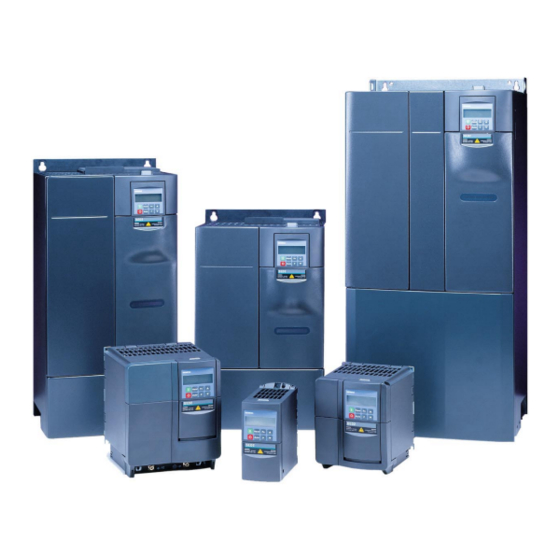
These are the Operating Instructions for the SED2 and are to be used for quick and simple commissioning. The SED2 range comprises VSDs for controlling the speed of fans and pump motors. The SED2 can also be programmed to manage many other motor functions and limits. These functions are set by parameters, which are programmed with the help of the operator panel. -
Page 9: Mechanical Installation
Mechanical installation 3.1 Mounting 3.1.1 Drilling plan for SED2 IP20 Frame size D, E and F Frame size A Frame size B and C Spacing Tightening Frame size Mounting material torque H in mm W in mm 2 x M4 screws... -
Page 10: Clearances For Sed2 Of The Ip20 Range
3.1.2 Clearances for SED2 of the IP20 range The IP20 range of SED2 units can be mounted side by side without space in between. Keep the following minimal clearance above and below the VSD for the movement of cooling air: ≥... -
Page 11: Clearances For Sed2 Of The Ip54 Range
3.1.4 Clearances for SED2 of the IP54 range When mounting SED2 of protection class IP54, observe the following horizontal and vertical clearances: Frame size Min. horizontal clearance S Min. vertical clearance V min. min. in mm in mm B, C... -
Page 12: Emc-Compatible Installation Of Sed2
EMC are taken: • When installed in accordance with the wiring SED2 recommendations of this Manual. The units comply with the European Norm EN 61800-3, “Adjustable speed electrical power drive systems”. This standard specifies different limits for domestic and industrial applications, which define whether an integral EMC filter is required •... -
Page 13: Emc-Compatible Wiring
VSD using a short potential equalization line (potential equalization rail) PLC: Programmable Logic Controller BACS: Building Automation and Control System 13 / 100 Siemens Commissioning Guide CM1G5192en Building Technologies 4 EMC-compatible installation of SED2 29.07.2010... -
Page 14: Routing The Cables
Signal and control cables Motor cable 14 / 100 Siemens Commissioning Guide CM1G5192en Building Technologies 4 EMC-compatible installation of SED2 29.07.2010... - Page 15 Shielded cables Strain relief rail For the use of plastic or metal cable glands, refer to subsections 5.1.2 and 5.1.3 IP20: Example of EMC-compatible installation and wiring of SED2 without gland plates Control cabinet Metal partition C-profile rail Monoblock...
-
Page 16: Cable Shielding Connections
IP20: EMC-compatible wiring of SED2 by means of gland plates (frame sizes A…C) Metal partition I/O modules SED2 SED2 C-profile rail SED2 Plastic housing Supply air Extract air frame sizes A...C 5192Z38de Gland plate Connection and potential equalization rail Strain relief rail... -
Page 17: Electrical Installation
Carrier rail Note: For SED2 IP20 frame sizes A…C, we recommend to use gland plates (available as optional accessory, mentioned below). Gland plates simplify and improve the connection of shielded cables. They allows for better contact of the shields and thus optimize the EMC behavior of the VSD. -
Page 18: Wiring Sed2 Ip54
Metal cable glands only Metal or plastic cable glands Motor cable shielded Mains cable Signal and control cables shielded 5.1.2 Dimensions of cable entries in the gland plates of SED2 IP54 Number of entries Frame size 20.0 mm dia. 25.0 mm dia. -
Page 19: Cabling Sed2 Ip54 Of Frame Sizes B And C
5.1.3 Cabling SED2 IP54 of frame sizes B and C All cable glands for frame sizes B and C made of plastic 19 / 100 Siemens Commissioning Guide CM1G5192en Building Technologies 5 Electrical installation 29.07.2010... -
Page 20: Wiring Sed2 Ip20
5.2 Wiring SED2 IP20 5.2.1 Access to the connection terminals: Frame size A Removing the terminal cover of the I/O module and the I/O module itself 5.2.2 Access to the connection terminals: Frame sizes B and C Removing the cover of... -
Page 21: Access To The Connection Terminals: Frame Sizes D
5.2.3 Access to the connection terminals: Frame sizes D…F IP20 Removing the operator panel (BOP or AOP) Opening the housing: Frame sizes D and E Opening the housing: Frame size F 21 / 100 Siemens Commissioning Guide CM1G5192en Building Technologies 5 Electrical installation 29.07.2010... -
Page 22: Power And Motor Terminals: Frame Sizes A
5.2.4 Power and motor terminals: Frame sizes A…F Terminal layout: Frame size A (Ground) (Ground) Terminal layout: Frame sizes B and C DC- DC+ Terminal layout: Frame sizes D and E 5192Z07 22 / 100 Siemens Commissioning Guide CM1G5192en Building Technologies 5 Electrical installation 29.07.2010... -
Page 23: Power Connection For Vsds With Built-In Emc Filter
5.2.5 Power connection for VSDs with built-in EMC filter Power connection to the The SED2 with frame sizes A, B, and C are delivered with built-in ready wired EMC footprint filter for frame footprint filters. Route the power supply to the terminals of the preinstalled footprint sizes A…C... - Page 24 Power connection at the SED2 with frame sizes D, E, and F are delivered with built-in ready wired EMC integrated EMC filter for filters. Wire the power supply to the connections of the built-in filter. The diagram frame sizes D…F below shows how to access the mains connections of the built-in filter.
- Page 25 25 / 100 Siemens Commissioning Guide CM1G5192en Building Technologies 5 Electrical installation 29.07.2010...
-
Page 26: Tightening Torque For The Connection Terminals
5192Z09en 5.2.6 Tightening torque for the connection terminals Frame size Tightening torque 2.25 10 (max.) 10 (max.) 5.2.7 Dimensions of cable entries in the gland plates of SED2 IP20 Frame size Number of entries 18.8 mm 22.8 mm 28.0 mm 46.0 mm... -
Page 27: Connecting The Motor
5.3 Connecting the motor Connect the motor terminals U, V, W of the VSD to the motor. SED2 Motor EMC filter 3 Phase 5.3.1 Direction of rotation You can change the direction of rotation of the motor by cross-connecting 2 of the output conductors at the VSD or the motor. -
Page 28: External Motor Overload Protection
PTC temperature sensor or a Klixon thermal switch which is to be connected to the VSD control terminals 14 and 15 according to the diagrams shown here. Klixon N.C. SED2 SED2 control Control terminals terminals 1 kΩ... -
Page 29: Interconnecting Sed2 Via Rs-485
5.5 Interconnecting SED2 via RS-485 Note: If a 0 V signal is available on the BMS, ideally this should be connected to the 0 V terminal 2 of the SED2. 5.5.1 RS-485 bus termination Buses not equipped with terminating resistors can cause errors in data communication. For this reason, the RS-485 bus should be provided with a terminating resistor. -
Page 30: Commissioning
Only authorized personnel trained in the setup, installation, commissioning and operation of the product may work on the product and plant. Danger ♦ SED2 operate at high voltages ♦ Operation of electrical equipment inevitably involves the use of dangerous voltages in some components ♦... -
Page 31: Dip Switch Settings
1 0 1 1 SED2 frame size A I/O module In all versions of the SED2, the DIP switches for setting the mains frequency and selecting US or European units of measurement are located on the control board under the I/O module. -
Page 32: Checkliste Für Die Inbetriebnahme
- Is the SED2 dirty or dusty? If that is the case, it must be cleaned. Dirt and dust shorten the equipment’s service life. This applies especially to cooling equipment (fan and cooling fins) which, in... - Page 33 Has the current parameter data set been read out and saved with the EasyComm software? Note: - We recommend to save the current data set of the SED2. This will enable you to always retrieve the existing default settings of the application should a problem occur or should a service visit become...
-
Page 34: Buttons And Their Functions On The Operator Panel (Bop And Aop)
Pressing this button while the VSD is running sets the input logic so that the operator controls Changeover to the SED2. In this mode, none of the controlled variables have any influence on the control of manual control the VSD. -
Page 35: Setting Parameters With The Bop Or Aop
Press to confirm and save the value Press until r0000 is displayed Press to revert to the standard motor display (as defined by the customer) 35 / 100 Siemens Commissioning Guide CM1G5192en Building Technologies 6 Commissioning 29.07.2010... -
Page 36: Quick Commissioning
1 = End with motor calculation and factory reset (recommended) 2 = End with motor calculation and with I/O reset 3 = End with motor calculation but without I/O reset 36 / 100 Siemens Commissioning Guide CM1G5192en Building Technologies 6 Commissioning... -
Page 37: Motor Identification
P1910 measures the stator’s resistance. Motor identification improves the performance of the VSD, especially in connection with the “Flying restart“ function or when not using Siemens standard motors. We recommend to perform motor identification directly after quick commissioning. If motor identification shall be performed on an... -
Page 38: Additional Parameters
During the time the measurement is made, warning A541 appears on the display. With the next start command, the VSD will operate using the new values. 38 / 100 Siemens Commissioning Guide CM1G5192en Building Technologies 6 Commissioning... -
Page 39: Copying Sed2 Parameters
Quick commissioning only for motor data Check motor data Caution! The motor data specified for use by the SED2 must accord with those of the connected motor! In particular, the ramp-up time (P1120) and ramp-down time (P1121) must be matched to the motor in use. -
Page 40: Automatic Restart
The ON command must be delivered via a digital input (DIN). When using setting 6, the motor is immediately restarted. The number of restart attempts are unlimited. P1211 is disabled. 40 / 100 Siemens Commissioning Guide CM1G5192en... - Page 41 SED2 Display of error Restart (P1211 = max. 10) P1212 1st attempt restarts successfully the SED2 since it was only a sporadic error of short duration Error relay P0731 (52.3) remains open and does not change over 41 / 100...
-
Page 42: Resetting To Factory Defaults
When using setting 1210 = 7, note the following: a) If, during a restart attempt of the SED2, the ON command is withdrawn, the SED2 stops immediately and “r oFF“ is constantly displayed. When the ON command is active again, the restart process is resumed. -
Page 43: Applications
Motor temperature sensor PTC thermistor Press and then to select r0000 Press to access the display Refer to subsection 7.1.2 “Recommended ramp times as a function of SED2 output“ 43 / 100 Siemens Commissioning Guide CM1G5192en Building Technologies 7 Applications... -
Page 44: Recommended Ramp Times As A Function Of Sed2 Output
P0758(0) 16.67% Value y1 Minimum frequency at 0 V P2000 60 Hz Reference frequency 7.1.2 Recommended ramp times as a function of SED2 output SED2 output Frame size Ramp time 0.37 - 4 kW A - B 30 s 5.5 - 15 kW 60 s 18.5 - 30 kW... -
Page 45: Parameter Changes
– Error message via relay output 1 – Indication of operation via relay output 2 – 22°C Fuses Error Relay 1 Relay 2 SED2 P(1) - Switch on/off - External alarm Hand Auto SED2 Building Management System (BMS) 5192A03en DIP switch setting... -
Page 46: Parameter Changes
External alarm to digital input 2; in the event of an alarm, the fan will be stopped – Error message via relay output 1 – Indication of operation via relay output 2 – Fuses Error Relay 1 Relay 2 SED2 P(1) - Switch on/off - External alarm Hand Auto SED2 Building Management System (BMS) 5192A04Aen... -
Page 47: Parameter Changes
PID acting direction Indirect P2200(0) Enable PID controller PID controller enabled P2280 PID proportional gain P2285 60 s PID integral action time r2262 Current setpoint r2272 Current feedback 47 / 100 Siemens Commissioning Guide CM1G5192en Building Technologies 7 Applications 29.07.2010... -
Page 48: Application 5
Booster function via digital input 3 (rpm = 100%) – Error message via relay output 1 – Indication of operation via relay output 2 – Fuses Error Relay 1 Relay 2 SED2 P(1) - Switch on/off - External alarm Hand - Booster Auto SED2 Building Management System (BMS) - Page 49 Error message via relay output 1 – Indication of operation via relay output 2 – Fuses Error Relay 1 Relay 2 SED2 P(1) - On: Speed high - On: Speed low Hand - External alarm Auto SED2 Building Management System...
-
Page 50: Parameter Changes
PID acting direction Indirect P2200(0) Enable PID controller PID controller enabled P2280 PID proportional gain P2285 30 s PID integral action time r2262 Current setpoint r2272 Actual value 50 / 100 Siemens Commissioning Guide CM1G5192en Building Technologies 7 Applications 29.07.2010... -
Page 51: Application 6
QAE22A for temperature control – Error message via relay output 1 – Indication of operation via relay output 2 – Fuses Error Relay 1 Relay 2 - Hand SED2 - Off P(1) - Auto Chiller Hand Auto Building Management System SED2 (BMS) 5192A07en... -
Page 52: Application 7
ON / OFF by LLSV relay interlock – QBE620 for pressure control – Indication of operation via relay output 2 – Fuses Error Relay 1 Relay 2 SED2 LLSV relay interlock P(1) Hand Auto SED2 5192A08en DIP switch setting Inspection switch 1 = Analog input 1 ■... -
Page 53: Parameter Changes
Lower torque threshold 2 P2185 Upper torque threshold 1 P2186 Lower torque threshold 1 Frequency [Hz] P2183 P2182 P2184 Threshold frequency 2 Threshold frequency 1 Threshold frequency 3 53 / 100 Siemens Commissioning Guide CM1G5192en Building Technologies 8 Additional functions 29.07.2010... -
Page 54: Parameter Setting
It is 30 s used for both methods of fault detection P2181 Belt failure detection mode Trip on high / low torque / speed 54 / 100 Siemens Commissioning Guide CM1G5192en Building Technologies 8 Additional functions 29.07.2010... -
Page 55: Belt Failure Detection With Sensor
8.2 Belt failure detection with sensor Carry out quick commissioning and modify the parameters for normal operation, then proceed as follows: SED2 Motor Encoder 8.2.1 Parameter setting Start with quick commissioning according to application 1 Par. no. Value Parameter function... -
Page 56: Hibernation Mode
Set the desired time T1 to T3 (before hibernation mode kicks in) (see diagram above) Define the PID frequency at which the motor has to P2392 …% Restart PID controller deviation [%] restart 56 / 100 Siemens Commissioning Guide CM1G5192en Building Technologies 8 Additional functions 29.07.2010... -
Page 57: Display Messages
P motor = r0027 * r0025 * root(3) * cosφ * η Motor power (P0307) exceeds VSD power Compare the SED2’s rating plate with that of the motor (P0206) F0002 Regenerative mode due to too short ramp-down... - Page 58 Check the SED2 as described in the SED2 Planning Manual (CM1J5192) Contact at SED2’s input or output Ensure that the SED2 is started only when the contact at the output is closed. If a change to bypass is made, ensure that OFF2 is activated before the output switch opens.
- Page 59 Is the component correctly plugged in and I/O EEPROM connected? fault (I/O board) − Check ASN of the I/O board. Is it an SED2 I/O board (SED2-IOBD1)? − A reset to the default values cancels all undesired parameter settings and retrieves the default settings.
- Page 60 − Check to ensure that the analog signal is fed to the right AIN. Measure the active analog signal only at the non-connected signal line, since a defective AIN at the SED2 can falsify the level of the analog signal, if measured with a measuring instrument while the connection is established...
-
Page 61: Warning Code List
Diagnostics and troubleshooting A0501 See F0001 Current limit A0502 See F0002 Overvoltage limit A0503 See F0003 Undervoltage limit A0504 See F0004 VSD over- temperature A0505 See F0005 VSD I 61 / 100 Siemens Commissioning Guide CM1G5192en Building Technologies 9 Display messages 29.07.2010... - Page 62 A0921 DAC parameter settings lead to inadmissible Check the parameter settings of the analog outputs values (P0770 - P0781) DAC parameters not correctly set 62 / 100 Siemens Commissioning Guide CM1G5192en Building Technologies 9 Display messages 29.07.2010...
-
Page 63: Other Messages
9.3 Other messages Display Cause, diagnostics and troubleshooting The SED2 is busy with tasks of higher priority. This can occur when changing important parameters, for P---- instance, when completing quick commissioning, or when resetting to the default parameters ... -
Page 64: Parameterization
Enable PID P2201 - P2231 Fixed setpoint P2240 - P2254 PID setpoint AOP (optional) P2253 - P2305 Standard setpoint Communication P2264 - r2272 PID feedback P2000 - r2091 64 / 100 Siemens Commissioning Guide CM1G5192en Building Technologies 10 Parameterization 29.07.2010... -
Page 65: Differences Between Sed2 Firmware Versions 1.20 And 1.30
10.2 Differences between SED2 firmware versions 1.20 and 1.30 Parameter Description Version 1.20 Version 1.30 P1200 Flying start Def: 0 Def: 3 P1202 Motor current: Flying start Def: 100% Def: 50% P1203 Search rate: Flying start Def: 100% Def: 50%... -
Page 66: System Parameter List For Levels 1 To 3
Level 3 Defines a limited set of parameters to which the enduser will have access. Value in brackets [] is identical with the parameter index, e.g. P0013[20] has 20 index values 66 / 100 Siemens Commissioning Guide CM1G5192en Building Technologies 10 Parameterization 29.07.2010... - Page 67 Unit: - Min: - Def: - Max: - Dependency: Value is displayed in [kW] or [hp] depending on setting for P0100 (for use in Europe / North America). 67 / 100 Siemens Commissioning Guide CM1G5192en Building Technologies 10 Parameterization 29.07.2010...
- Page 68 CDS Bit 0 (Local/Remote – Hand/Auto) 0 NO, 1 r 0055 CO/BO: Add. act. control word Level 3 Displays additional control word of VSD and can be used to diagnose which commands are active. 68 / 100 Siemens Commissioning Guide CM1G5192en Building Technologies 10 Parameterization 29.07.2010...
- Page 69 Def: - Max: - Value: r0208=230 : 200 - 240 V +/- 10% r0208=400 : 380 - 480 V +/- 10% r0208=575 : 500 - 600 V +/- 10% 69 / 100 Siemens Commissioning Guide CM1G5192en Building Technologies 10 Parameterization 29.07.2010...
- Page 70 Stator resistance value in [Ohms] for the connected motor (from line to line). The parameter value includes the cable resistance. Unit: Ohm Min: 0.00001 Def: 4.0 Max: 2000.0 70 / 100 Siemens Commissioning Guide CM1G5192en Building Technologies 10 Parameterization 29.07.2010...
- Page 71 Max: 2 Settings: 0=No sensor 1=PTC thermistor 2=KTY84 Dependency: If “no sensor” is selected, motor temperature monitoring occurs based on the estimated value of the thermal motor model. 71 / 100 Siemens Commissioning Guide CM1G5192en Building Technologies 10 Parameterization 29.07.2010...
- Page 72 Function of digital input 8 Level 3 Selects function of digital input 8 (via analog input). Unit: - Min: 0 Def: 0 Max: 99 Detail: See P0707 (function of digital input7). 72 / 100 Siemens Commissioning Guide CM1G5192en Building Technologies 10 Parameterization 29.07.2010...
- Page 73 Unit: % Min: - Def: - Max: - Index: r0754[0]: Analog input 1 (ADC 1) r0754[1]: Analog input 2 (ADC 2) Dependency: P0757 to P0760 define range (ADC scaling) 73 / 100 Siemens Commissioning Guide CM1G5192en Building Technologies 10 Parameterization 29.07.2010...
- Page 74 ADC scaling curve), if sign of P0758 and P0760 are opposite. Fmin (P1080) should be zero when using center zero setup. There is no hysteresis at the end of the dead band. 74 / 100 Siemens Commissioning Guide CM1G5192en Building Technologies 10 Parameterization 29.07.2010...
- Page 75 Defines address of CB (communication board) or address of the other option modules. There are 2 ways to set the bus address: 1 via DIP switches on the PROFIBUS module 2 via a user-entered value 75 / 100 Siemens Commissioning Guide CM1G5192en Building Technologies 10 Parameterization...
- Page 76 JOG right NO, 1 Bit09 JOG left NO, 1 Bit10 Control from PLC NO, 1 Bit11 Reverse (setpoint inversion) NO, 1 Bit13 Motor potentiometer MOP up NO, 1 76 / 100 Siemens Commissioning Guide CM1G5192en Building Technologies 10 Parameterization 29.07.2010...
- Page 77 34=USS on BOP link + Fixed frequency 74=USS on BOP link + Analog setpoint 2 35=USS on COM link + Fixed frequency 75=USS on COM link + Analog setpoint 2 77 / 100 Siemens Commissioning Guide CM1G5192en Building Technologies 10 Parameterization...
- Page 78 P1022[1]: VSD in ”Hand” mode for Bit 2 P1023[0]: VSD in ”Auto” mode for Bit 3 P1023[1]: VSD in ”Hand” mode for Bit 3 Dependency: Accessible only if P0701 - P0706=99 (function of digital inputs=BICO). 78 / 100 Siemens Commissioning Guide CM1G5192en Building Technologies 10 Parameterization 29.07.2010...
- Page 79 Max: 150.00 Note: Value set here is valid both for clockwise and for counterclockwise rotation. Under certain conditions (e.g. ramping, current limiting), motor can run below minimum frequency. 79 / 100 Siemens Commissioning Guide CM1G5192en Building Technologies 10 Parameterization 29.07.2010...
- Page 80 Defines command source of RFG enable setpoint command (RFG: Ramp function generator). Unit: - Min: 0.00 Def: 1.0 Max: 4000.0 Index: . P1142[0]: VSD in ”Auto” mode P1142[1]: VSD in ”Hand” mode 80 / 100 Siemens Commissioning Guide CM1G5192en Building Technologies 10 Parameterization 29.07.2010...
- Page 81 3 or 4 (or after a fault if P1210=6). Unit: s Min: 0 Def: 30 Max: 1000 Note: The counter for restart attempts will be reset after a lapse of 30 seconds. 81 / 100 Siemens Commissioning Guide CM1G5192en Building Technologies 10 Parameterization 29.07.2010...
- Page 82 Motor supplied by mains YES, P1262 Bypass dead time Level 2 Time delay between switching contactors to allow motor to demagnetize. Unit: s Min: 0 Def: 1.000 Max: 20.000 82 / 100 Siemens Commissioning Guide CM1G5192en Building Technologies 10 Parameterization 29.07.2010...
- Page 83 (acceleration boost P1311 and starting boost P1312). However, priorities are allocated to these parameters as follows: P1310 > P1311 > P1312. Increasing the boost levels increases motor heating (especially at standstill). 83 / 100 Siemens Commissioning Guide CM1G5192en Building Technologies 10 Parameterization 29.07.2010...
- Page 84 Before selecting motor data identification, "Quick commissioning" has to be performed in advance. Once enabled (P1910=1), A0541 generates a warning that the next ON command will initiate measurement of motor parameters. When choosing the setting for measurement, observe the following: 84 / 100 Siemens Commissioning Guide CM1G5192en Building Technologies 10 Parameterization...
- Page 85 CI: PZD to CB Level 3 Connects PZD to CB. This parameter allows the user to define the source of status words and actual values for the reply PZD. (PZD: Process data). 85 / 100 Siemens Commissioning Guide CM1G5192en Building Technologies 10 Parameterization...
- Page 86 This threshold controls status bits 04 and 05 in status word 2 (r0053) and bits 01 and 02 in r2197. P2156 Delay time of threshold freq f_1 Level 3 Sets delay time prior to threshold frequency f_1 comparison (P2155). Unit: ms Min: 0 Def: 10 Max: 10000 86 / 100 Siemens Commissioning Guide CM1G5192en Building Technologies 10 Parameterization 29.07.2010...
- Page 87 CO/BO: Monitoring word 1 Level 3 Monitoring word 1 which indicates the state of monitor functions. Each bit represents one monitor function. Unit: - Min: - Def: - Max: - 87 / 100 Siemens Commissioning Guide CM1G5192en Building Technologies 10 Parameterization 29.07.2010...
- Page 88 Inactive P2207 Inactive Active Active Active P2208 Active Inactive Inactive Inactive P2209 Active Inactive Inactive Active P2210 FF10 Active Inactive Active Inactive P2211 FF11 Active Inactive Active Active 88 / 100 Siemens Commissioning Guide CM1G5192en Building Technologies 10 Parameterization 29.07.2010...
- Page 89 722.5=Digital input 6 (requires P0706 set to 99, BICO) Index: For P2226: For P2228: P2226[0]: VSD in ”Auto” mode P2228[0]: VSD in ”Auto” mode P2226[1]: VSD in ”Hand” mode P2228[1]: VSD in ”Hand” mode 89 / 100 Siemens Commissioning Guide CM1G5192en Building Technologies 10 Parameterization 29.07.2010...
- Page 90 Allows the user to scale the PID feedback as a percentage value [%]. A gain of 100% means that the feedback signal has not changed from its default value. Unit: - Min: 0.00 Def: 100.00 Max: 500.00 90 / 100 Siemens Commissioning Guide CM1G5192en Building Technologies 10 Parameterization 29.07.2010...
- Page 91 PID when the VSD is started. Once the limits have been reached, the PID controller output is instantaneous. These ramp times are used whenever a RUN command is given. Unit: s Min: 0.00 Def: 0.00 Max: 100.00 91 / 100 Siemens Commissioning Guide CM1G5192en Building Technologies 10 Parameterization 29.07.2010...
- Page 92 Staging: With pump (or fan) cascading: Starting process of an additional motor with constant speed to increase output Destaging: With pump (or fan) cascading: Stopping process of an additional motor with constant speed to decrease output 92 / 100 Siemens Commissioning Guide CM1G5192en...
- Page 93 (for example, if only motor rating plate data have been changed). Calculates a variety of motor parameters, overwriting previous values. These include P0344 (level 4, motor weight), P0347 (level 4, demagnetization time), P2000 (reference frequency), P2002 (reference current). 93 / 100 Siemens Commissioning Guide CM1G5192en Building Technologies 10 Parameterization 29.07.2010...
-
Page 94: Overview Of Factory And User Parameter Settings
99999.0 P0761 P1121 30.00 P2186 P0771 P1135 5.00 P2187 99999.0 P0773 P1140 P2188 P0776 P1141 P2189 99999.0 P0777 P1142 P2190 P0778 P1200 P2191 3.00 P0779 100.0 P1202 P2192 94 / 100 Siemens Commissioning Guide CM1G5192en Building Technologies 10 Parameterization 29.07.2010... - Page 95 P2268 -50.00 P2269 100.0 P2270 P2271 P2274 P2279 0.00 P2280 1.200 P2285 P2291 100.00 P2292 0.00 P2293 0.00 P2303 P2304 P2305 P2306 P2370 P2371 P2372 P2373 20.0 P2374 95 / 100 Siemens Commissioning Guide CM1G5192en Building Technologies 10 Parameterization 29.07.2010...
-
Page 96: Appendix
Safety of machinery – Electrical equipment of machines European guideline for machinery This guideline does not apply to the SED2 VSD product series. The products were tested comprehensively and evaluated for adherence to important guidelines pertaining to health and safety in a typical application. A declaration of conformity will be provided on request. -
Page 97: List Of Abbreviations
Positive Temperature Coefficient Process Data RCCB Residual Current Circuit-Breaker (FI circuit-breaker) Radio Frequency Interference Programmable Logic Controller Universal Serial Interface Protocol Water column (unit of pressure, in inches) 97 / 100 Siemens Commissioning Guide CM1G5192en Building Technologies 11 10BAppendix 29.07.2010... - Page 98 98 / 100 Siemens Commissioning Guide CM1G5192en Building Technologies 11 10BAppendix 29.07.2010...
- Page 99 99 / 100 Siemens Commissioning Guide CM1G5192en Building Technologies 11 10BAppendix 29.07.2010...
- Page 100 Siemens Switzerland Ltd Building Technologies Division International Headquarters Gubelstrasse 22 CH-6301 Zug Tel. +41 41-724 24 24 Fax +41 41-724 35 22 © 2001-2010 Siemens Switzerland Ltd www.siemens.com/sbt Subject to change 100 / 100 Siemens Commissioning Guide CM1G5192en Building Technologies...