Table of Contents
Advertisement
Quick Links
SIMATIC
S7-300, CPU 31xC and CPU 31x:
Installation
Operating Instructions
This manual is part of the documentation package
with the order number: 6ES7398-8FA10-8BA0
Edition 08/2004
A5E00105492-05
Preface
Guide to the S7-300
documentation
Installation Order
S7-300 components
Configuring
Installing
Wiring
Addressing
Commissioning
Maintenance
Debugging functions, dia-
gnostics and troubleshooting
Appendix
1
2
3
4
5
6
7
8
9
10
A
Advertisement
Table of Contents

Related Manuals for Siemens Simatic S7-300 CPU 31xC Series


Summary of Contents for Siemens Simatic S7-300 CPU 31xC Series
- Page 1 Preface Guide to the S7-300 documentation Installation Order SIMATIC S7-300 components S7-300, CPU 31xC and CPU 31x: Configuring Installation Installing Operating Instructions Wiring Addressing Commissioning Maintenance Debugging functions, dia- gnostics and troubleshooting Appendix This manual is part of the documentation package with the order number: 6ES7398-8FA10-8BA0 Edition 08/2004 A5E00105492-05...
-
Page 2: Edition
Trademarks All designations marked with ® are registered trademarks of Siemens AG. Other designations in this documentation might be trademarks which, if used by third parties for their purposes, might infringe upon the rights of the proprietors. -
Page 3: Operating Instructions, Edition 08/2004,
Note The special features of the 315F-2 DP and CPU 317F-2 DP CPUs are described in their Product Information, available on the Internet at http://www.siemens.com/automation/service&support, article ID 17015818. S7-300, CPU 31xC and CPU 31x: Installation Operating Instructions, Edition 08/2004, A5E00105492-05... - Page 4 Preface Note There you can obtain the descriptions of all current modules. For new modules, or modules of a more recent version, we reserve the right to include a Product Information containing latest information. Approvals The SIMATIC S7-300 product series has the following approvals: •...
- Page 5 Preface Documentation classification This manual is part of the S7-300 documentation package. Name of the manual Description Manual Control and display elements, communication, memory concept, cycle and response times, 31xC and 31x CPUs, technical data • technical data Reference Manual Control and display elements, communication, memory concept, cycle and response times, CPU data: CPU 312 IFM –...
- Page 6 Preface Additional information required: Name of the manual Description Reference Manual Description of the SFCs, SFBs and OBs. System software for S7-300/400 system and standard This manual is part of the STEP 7 functions documentation package. For further information, refer to the STEP 7 Online Help.
-
Page 7: Table Of Contents
Table of contents Preface ..............................iii Guide to the S7-300 documentation ....................... 1-1 Installation Order ............................ 2-1 S7-300 components..........................3-1 Example of an S7-300 configuration..................3-1 Overview of the vital modules of an S7-300 ................3-2 Configuring ............................. 4-1 Overview ............................ 4-1 Basic engineering principles ...................... - Page 8 Table of contents 4.11.3.6 Connectors and other components for Ethernet..............4-56 4.11.3.7 Example of a PROFINET Subnet .................... 4-57 4.11.3.8 Example of a PROFINET IO system..................4-59 4.11.4 Routed network transitions....................... 4-60 4.11.5 Point-to-point (PtP)........................4-62 4.11.6 Actuator/sensor interface (ASI) ....................4-63 Installing ..............................
- Page 9 Table of contents 8.4.5.1 Connecting a PG/PC to the integrated PROFINET interface of the CPU 31x-2 PN/DP ..8-13 8.4.5.2 Connecting the PG to a node....................8-14 8.4.5.3 Connecting the PG to several nodes ..................8-15 8.4.5.4 Using the PG for commissioning or maintenance..............8-16 8.4.5.5 Connecting a PG to ungrounded MPI nodes (not CPU 31xC) ..........
- Page 10 Table of contents Appendix..............................A-1 General Rules and Regulations for S7-300 Operation ..............A-1 Protection against electromagnetic interference................A-3 A.2.1 Basic Points for EMC-compliant system installations ..............A-3 A.2.2 Five basic rules for securing EMC .....................A-5 A.2.2.1 1. Basic rule for ensuring EMC ....................A-5 A.2.2.2 2.
- Page 11 Table of contents Tables Table 1-1 Ambient influence on the automation system (AS)..............1-1 Table 1-2 Galvanic isolation........................1-1 Table 1-3 Communication between sensors/actuators and the PLC............1-2 Table 1-4 The use of local and distributed I/O ................... 1-2 Table 1-5 Configuration consisting of the Central Unit (CU) and Expansion Modules (EMs) ....
- Page 12 Table of contents Table 5-2 Installation tools and materials....................5-3 Table 5-3 Mounting holes for rails ......................5-5 Table 5-4 Slot numbers for S7 modules..................... 5-9 Table 6-1 Wiring accessories ........................6-1 Table 6-2 Tools and material for wiring ...................... 6-1 Table 6-3 Wiring conditions for PS and CPU .....................
- Page 13 Table of contents Table 10-8 BF2/ BUSF LED is lit......................10-17 Table 10-9 BF2/ BUSF LED flashes on a PROFINET IO controller ............10-17 Table 10-10 Event detection of CPU 31x2 operating as DP master ............10-20 Table 10-11 Evaluating RUN to STOP transitions of the DP slave in the DP master........ 10-20 Table 10-12 Reading out diagnostic data in the master system, using STEP 5 and STEP 7 ....
- Page 14 Table of contents S7-300, CPU 31xC and CPU 31x: Installation Operating Instructions, Edition 08/2004, A5E00105492-05...
-
Page 15: Guide To The S7-300 Documentation
Guide to the S7-300 documentation Overview This guide leads you through the S7-300 documentation. Selecting and configuring Table 1-1 Ambient influence on the PLC Information on.. is available in ... What provisions do I have to make for PLC installation S7-300, CPU 31xC and CPU 31x Manual: Installation: space? Configuring - Component dimensions... -
Page 16: Table 1-3 Communication Between Sensors/Actuators And The Plc
Guide to the S7-300 documentation Table 1-3 Communication between sensors/actuators and the PLC Information on.. is available in ... Which module is suitable for my sensor/actuator? For CPU: CPU 31xC and CPU 31x Manual, Technical Data For signal modules: Reference manual of your signal module How many sensors/actuators can I connect to the module? For CPU: CPU 31xC and CPU 31x Manual, technical data... -
Page 17: Table 1-6 Cpu Performance
Guide to the S7-300 documentation Table 1-6 CPU performance Information on.. is available in ... Which memory concept is best suited to my application? CPU 31xC and CPU 31x Manual, Technical Data How do I insert and remove Micro Memory Cards? S7-300, CPU 31xC and CPU 31x operating instructions: Installation: Commissioning –... -
Page 18: Table 1-9 Supplementary Features
Guide to the S7-300 documentation Table 1-9 Supplementary features Information on.. is available in ... How to implement operating and monitoring functions For text-based displays: The relevant Manual (Human Machine Interface) For Operator Panels: The relevant Manual For WinCC: The relevant Manual How to integrate process control modules For PCS7: The relevant Manual Options of redundant and fail-safe systems... -
Page 19: Installation Order
Installation Order We will start by showing you the sequence of steps you have to follow to install your system. Then we will go on to explain the basic rules that you should follow, and how you can modify an existing system. Installation procedure Configuring Mounting... - Page 20 Installation Order Modifying the existing S7 system structure To modify the configuration of an existing system, proceed as described earlier. Note When adding a new signal module, always refer to the relevant module information. Reference SIMATIC S7-300 Also refer to the description of the various modules in the manual: Automation Systems, Module Data Reference Manual S7-300, CPU 31xC and CPU 31x: Installation Operating Instructions, Edition 08/2004, A5E00105492-05...
-
Page 21: S7-300 Components
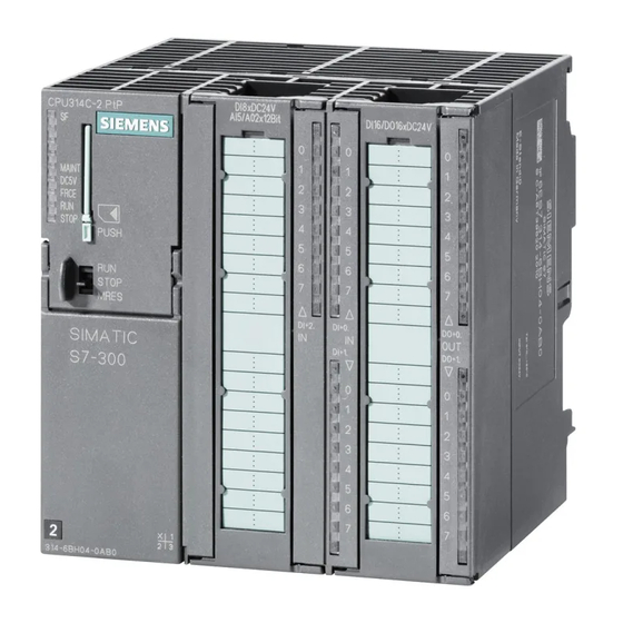
S7-300 components Example of an S7-300 configuration BUSF DC5 V FRCE ST OP BUSF DC5 V FRCE ST OP The figure illustrates the following S7-300 components the following Power supply (PS) module Central processing unit (CPU) The example in the figure shows a CPU 31xC with integrated I/O. Signal module (SM) PROFIBUS bus cable Cable for connecting a programming device (PG) -
Page 22: Overview Of The Vital Modules Of An S7-300
S7-300 and its 24 VDC load circuits. The CPU executes the user program, supplies 5 V to the S7-300 backplane Accessories: SIEMENS bus, and communicates with other Front connectors (CPU 31xC only) • nodes of an MPI network via the MPI interface. - Page 23 S7-300 components 3.2 Overview of the vital modules of an S7-300 Component Function Illustration Signal modules (SM) The SM matches different process signal levels to the S7-300. Digital input modules • Digital output modules • Digital I/O modules, • Analog input modules •...
- Page 24 S7-300 components 3.2 Overview of the vital modules of an S7-300 Component Function Illustration RS 485 repeater The repeater is used to amplify the signals and to couple segments of an MPI or PROFIBUS subnet. Switch A switch is used to interconnect the Ethernet nodes.
-
Page 25: Configuring
Configuring Overview There, you can find all the necessary information • for the mechanical configuration of an S7-300, • for the electrical configuration of an S7-300, • that has to be observed in networking. Reference Communication with SIMATIC • For further information, refer to the manual (6ES7398-8EA00-8AA0), or SIMATIC NET Twisted-Pair and Fiber-Optic Networks... - Page 26 Configuring 4.2 Basic engineering principles Caution Operation of an S7-300 in plants or systems is defined by special set of rules and regulations, based on the relevant field of application. Observe the safety and accident prevention regulations for specific applications, for example, the machine protection General rules and regulations on S7-300 operation directives.
- Page 27 Configuring 4.2 Basic engineering principles Horizontal and vertical installation You can mount an S7-300 either vertically or horizontally. The following ambient air temperatures are permitted: • Vertical assembly: 0 °C to 40 °C • Horizontal assembly: 0 °C to 60 °C Always install the CPU and power supply modules on the left or at the bottom.
-
Page 28: Component Dimensions
Configuring 4.3 Component dimensions Component dimensions Length of the mounting rails Table 4-1 Mounting rails - Overview Mounting rail length Usable length for modules Order number 160 mm 120 mm 6ES7 390-1AB60-0AA0 482.6 mm 450 mm 6ES7 390-1AE80-0AA0 530 mm 480 mm 6ES7 390-1AF30-0AA0 830 mm... -
Page 29: Table 4-3 Shielding Terminals - Overview
Configuring 4.3 Component dimensions Shielding contact element The direct contact between the shielding contact element and the mounting rail makes it easy for you to connect all shielded cables of your S7 modules to ground. The figure illustrates the following Shielding terminals The bracket. -
Page 30: Required Clearances
Configuring 4.4 Required clearances Required clearances You must maintain the clearance shown in the figure in order to provide sufficient space for installing the modules, and to allow the dissipation of heat generated by the modules. The S7-300 assembly on multiple racks shown in the figure below shows the clearance between racks and adjacent components, cable ducts, cabinet walls etc. -
Page 31: Arrangement Of Modules On A Single Rack
Configuring 4.5 Arrangement of modules on a single rack Arrangement of modules on a single rack Reasons for using one or multiple racks The number of racks you need will depend on your application. Reasons for using a single rack: Reasons for distributing modules between several racks Compact, space-saving use of all your... -
Page 32: Distribution Of Modules To Several Racks
Configuring 4.6 Distribution of modules to several racks Distribution of modules to several racks Exceptions With CPU 312 and CPU 312C, only a single-row configuration on a rack is possible. Using interface modules If you are planning an assembly in multiple racks, then you will need interface modules (IM). Interface modules route the backplane bus of an S7-300 to the next rack. - Page 33 Configuring 4.6 Distribution of modules to several racks Rules: arrangement of the modules on several racks Please note the following points if you wish to arrange your modules on multiple racks: • The IM always uses slot 3 (slot 1: power supply module; slot 2: CPU, slot 3: Interface module) •...
- Page 34 Configuring 4.6 Distribution of modules to several racks Example: Full assembly using four racks The figure shows the arrangement of modules in an S7-300 assembly on 4 racks. SM1 SM2 SM3 SM 4 SM5 SM6 SM7 SM8 SM1 SM2 SM3 SM 4 SM5 SM6 SM7 SM8 SM1 SM2 SM3 SM 4 SM5 SM6 SM7 SM8 SM1 SM2 SM3 SM4 SM5 SM6 SM7 SM8 The figure illustrates the following...
-
Page 35: Selection And Installation Of Cabinets
Reference for power loss For detailed information on power dissipation, refer to the Siemens catalogs NV21 and ET1. Specification of cabinet dimensions Note the following specifications when you determine the dimensions of a cabinet for your S7-300 installation: •... - Page 36 Configuring 4.7 Selection and installation of cabinets Warning Modules may get damaged if exposed to excess ambient temperatures. Reference for ambient temperatures S7-300 Automation System, For information on permitted ambient temperatures, refer to the Module data Reference Manual. S7-300, CPU 31xC and CPU 31x: Installation 4-12 Operating Instructions, Edition 08/2004, A5E00105492-05...
-
Page 37: Table 4-5 Cabinet Types
Configuring 4.7 Selection and installation of cabinets Overview of typical cabinet types The table below gives you an overview of commonly used cabinet types. It shows you the applied principle of heat dissipation, the calculated maximum power loss and the degree of protection. -
Page 38: Example: Selecting A Cabinet
Configuring 4.8 Example: Selecting a cabinet Example: Selecting a cabinet Introduction The sample below clearly shows the maximum permitted ambient temperature at a specific power loss for different cabinet designs. Installation The following device configuration should be installed in a cabinet: •... -
Page 39: Electrical Assembly, Protective Measures And Grounding
Configuring 4.9 Electrical assembly, protective measures and grounding Result The figure below shows the resultant ambient temperatures, based on an accumulated power loss of 650 W: Table 4-6 Cabinet selection Cabinet design Maximum permitted ambient temperature Closed with natural convection and forced convection (trend Operation not possible Open with through-ventilation (trend 2) approx. -
Page 40: Installing An S7-300 With Grounded Reference Potential
Configuring 4.9 Electrical assembly, protective measures and grounding Specified components and protective measures A number of components and protective measures are prescribed for plant installations. The type of components and the degree of compulsion pertaining to the protective measures will depend on the VDE specification applicable to your particular plant. -
Page 41: Configuring An S7-300 With Ungrounded Reference Potential (Not Cpu 31Xc)
Configuring 4.9 Electrical assembly, protective measures and grounding Grounded reference potential of the CPU 31x The figure shows an S7-300 configuration with grounded reference potential (factory state.) <100 nF The figure illustrates the following Grounding slide contact in grounded state Ground of the internal CPU circuitry The mounting rail Note... - Page 42 Configuring 4.9 Electrical assembly, protective measures and grounding Application In large systems, the S7-300 may require a configuration with grounded reference potential due to ground-fault monitoring. This is the case, for example, in chemical industry and power stations. Ungrounded reference potential of the CPU 31x The figure shows an S7-300 configuration with floating potential <100 nF The figure illustrates the following...
-
Page 43: Modules With Isolated Or Common Potential
Configuring 4.9 Electrical assembly, protective measures and grounding 4.9.4 Modules with isolated or common potential? Isolated modules Isolated modules are installed with galvanic isolation between the reference potentials of the control circuit (M ) and load circuit (M internal external Field of application Use isolated modules for: •... - Page 44 Configuring 4.9 Electrical assembly, protective measures and grounding Example: Assembly with CPU 31xC and isolated modules The figure below shows an example of such a configuration: A CPU 31xC with isolated modules. The CPU 31xC (1) is automatically grounded. S7-300 CPU internal Data internal...
-
Page 45: Grounding Measures
Configuring 4.9 Electrical assembly, protective measures and grounding Example: Installing an S7-300 with common potential modules When using an SM 334 AI 4/AO 2 analog I/O module, connect one of the grounding terminals M to the CPU's chassis ground. analog The figure below shows an example of such a configuration: An S7-300 with common potential modules 4AI/2AO... -
Page 46: Table 4-8 Measures For Protective Grounding
Configuring 4.9 Electrical assembly, protective measures and grounding Measures for protective grounding The table below shows an overview of the most important measures for protective grounding. Table 4-8 Measures for protective grounding Device Measures Cabinet / mounting frame Connection to central ground (equipotential busbar, for example) using cables with protective conductor quality Rack / mounting rail Connection to central ground, using cables with a minimum cross-... - Page 47 Configuring 4.9 Electrical assembly, protective measures and grounding Rule: Load circuit grounding You should always ground the load circuits. This common reference potential (ground) ensures proper functioning. Note (not valid for CPU 31xC): If you want to locate a fault to ground, provide your load power supply (terminal L or M) or the isolating transformer with a removable connection to the protective conductor (see Overview: Grounding section 4).
-
Page 48: Overview: Grounding
Configuring 4.9 Electrical assembly, protective measures and grounding 4.9.6 Overview: Grounding CPU 31xC The figure below shows you the complete assembly of an S7-300 with CPU 31xC with a power supply from TN-S mains. Apart from powering the CPU, the PS 307 also supplies the load current for the 24 VDC modules. -
Page 49: Table 4-11 Connecting The Load Voltage Reference Potential
Configuring 4.9 Electrical assembly, protective measures and grounding All CPUs except CPU 31xC The figure below shows you the complete assembly of an S7-300 with TN-S mains supply (does not apply to CPU 31xC). Apart from powering the CPU, the PS 307 also supplies the load current for the 24 VDC modules. -
Page 50: Selecting The Load Power Supply
Modules requiring voltage Safety isolation This is a common feature of the supplies ≤ 60 VDC or ≤ 25 VAC. Siemens power supply series PS 307 and SITOP power 24 VDC load circuits series 6EP1. Output voltage tolerances: 20.4 V to 28.8 V 24 VDC load circuits 40.8 V to 57.6 V... - Page 51 Configuring 4.10 Selecting the load power supply Example: S7-300 with load power supply from PS 307 The figure below shows the overall S7-300 configuration (load power supply unit and grounding concept), with TN-S mains supply. The PS 307 supplies the CPU and the load current circuit of the 24 VDC modules.
-
Page 52: Planning Subnets
Configuring 4.11 Planning subnets 4.11 Planning subnets 4.11.1 Overview Subnets Subnets available in SIMATIC for the various automation levels (process, cell, field and actuator/sensor level ): • Multi-Point Interface (MPI) • PROFIBUS • PROFINET (Industrial Ethernet) • Point-to-point communication (PtP) •... - Page 53 Configuring 4.11 Planning subnets PROFINET (Industrial Ethernet) Availability: CPUs with a "PN" name suffix are equipped a second interface, namely the PROFINET interface (CPU 317-2 PN/DP, for example) A PROFINET interface, or communication processors, can be used to implement Industrial Ethernet in an S7-300 CPU system.
-
Page 54: Configuring Mpi And Profibus Subnets
Configuring 4.11 Planning subnets 4.11.2 Configuring MPI and PROFIBUS subnets 4.11.2.1 Overview The next section contains all the information you require to configure MPI, PtP and PROFIBUS subnets: Contents • MPI, PtP and PROFIBUS subnets • Multi-Point Interface • PROFIBUS DP •... - Page 55 Configuring 4.11 Planning subnets Number of nodes Maximum number of nodes per subnet: Table 4-13 Subnet nodes Parameters PROFIBUS DP Number Addresses 0 to 126 0 to 125 Note Default: 32 addresses of those: 1 master (reserved) Reserved addresses: • 1 PG connection (address 0 reserved) •...
-
Page 56: Table 4-15 Mpi Addresses Of Cps/Fms In An S7-300 System
Configuring 4.11 Planning subnets Differences in the MPI addresses of CPs/FMs in an S7300 system Table 4-15 MPI addresses of CPs/FMs in an S7-300 system Options Example Example: BUSF BUSF A system containing an S7-300 CPU and 2 V DC5 V FRCE FRCE CPs. -
Page 57: Multi-Point Interface (Mpi)
Configuring 4.11 Planning subnets Equipotential bonding For information on what to take into account with respect to equipotential bonding in your network configuration, refer to the corresponding chapter in the appendix. Reference CPU 31xC and CPU 31x For further information, refer to the Communication section in Manual, Technical Data 4.11.2.3 Multi-Point Interface (MPI) -
Page 58: Profibus Dp Interface
Configuring 4.11 Planning subnets 4.11.2.4 PROFIBUS DP interface Availability CPUs with “DP“ name suffix are equipped at least with a DP X2 interface. The 315-2 PN/DP and 317 CPUs are equipped with an MPI/DP X1 interface. A CPU with MPI/DP interface is supplied with default MPI configuration. You need to set DP mode in STEP 7 if you want to use the DP interface. -
Page 59: Network Components Of Mpi/Dp And Cable Lengths
Configuring 4.11 Planning subnets Devices capable of PROFIBUS DP communication • PG/PC • OP/TP • DP slaves • DP master • Actuators/Sensors • S7-300/S7-400 with PROFIBUS DP interface Reference Further information on PROFIBUS: http://www.profibus.com 4.11.2.5 Network components of MPI/DP and cable lengths MPI subnet segment You can install cables with a length of up to 50 m in an MPI subnet segment. - Page 60 Configuring 4.11 Planning subnets Longer cable lengths via RS 485 repeater You need to install RS485 repeaters for segments requiring cable lengths longer than the allowed length. For further information, refer to the RS485 Repeater Product Information. Stub cables Make allowances for the maximum stub cable length when you connect bus nodes to a bus segment by means of stub cables, for example, a PG via standard PG cable.
-
Page 61: Table 4-21 Available Bus Cables
Configuring 4.11 Planning subnets PROFIBUS cables For PROFIBUS DP or MPI networking we offer you the following bus cables for diverse fields of application: Table 4-21 Available bus cables Bus cable Order number PROFIBUS cable 6XV1 830-0AH10 PROFIBUS cable, halogen-free 6XV1 830-0CH10 PROFIBUS underground cable 6XV1 830-3AH10... -
Page 62: Table 4-23 Marginal Conditions For Wiring Interior Bus Cables
Configuring 4.11 Planning subnets Installation of bus cables When you install PROFIBUS cables, you must not • twist, • stretch • or compress them. When wiring indoor bus cables, also maintain the following marginal conditions (d = outer cable diameter): Table 4-23 Marginal conditions for wiring interior bus cables Characteristics... - Page 63 Configuring 4.11 Planning subnets RS 485 repeater Type Order number RS 485 repeater 6ES7 972-0AA00-0XA0 Purpose RS485 repeaters are used to amplify data signals on bus lines and to couple bus segments. You require this RS 485 Repeater in the following situations: •...
-
Page 64: Cable Lengths Of Mpi And Profibus Subnets
Configuring 4.11 Planning subnets 4.11.2.6 Cable lengths of MPI and PROFIBUS subnets Example: Installation of an MPI subnet The figure below shows you the block diagram of a MPI subnet. S7-300 S7-300 S7-300 S7-300 BUSF BUSF DC5V DC5V FRCE FRCE STOP STOP OP 27... - Page 65 Configuring 4.11 Planning subnets Example: Maximum distances in the MPI subnet The figure below shows you: • a possible MPI subnet configuration • maximum distances possible in an MPI subnet • the principle of "Line extension" using RS 485 repeaters Key to numbers in the figure Terminating resistor enabled.
- Page 66 Configuring 4.11 Planning subnets Example: Terminating resistor in the MPI subnet The figure below shows you an example of an MPI subnet and where to enable the terminating resistor. The figure below illustrates where the terminating resistors must be enabled in an MPI subnet.
- Page 67 Configuring 4.11 Planning subnets Example: Installation of a PROFIBUS subnet The figure below shows you the basic principles of a PROFIBUS subnet installation. S7-300 S7-300 31x-2 DP PS ET 200M PS ET 200M PS ET 200 M PS ET 200M DP-CPU S5-95U MASTER...
- Page 68 Configuring 4.11 Planning subnets Example: CPU 314C-2 DP as MPI and PROFIBUSnode The figure below shows you an assembly with a CPU 314C-2 DP integrated in an MPI subnet and also operated as DP master in a PROFIBUS subnet. S7-300 S5-95U PS CPU DP address 7...
-
Page 69: Configuring Profinet Subnets
Configuring 4.11 Planning subnets 4.11.3 Configuring PROFINET subnets 4.11.3.1 Overview The next section contains all the information you require to configure PROFINET subnets: Contents • PROFINET nodes • Integration of field bus system into PROFINET • PROFINET IO and PROFINET CBA (Component-Based Automation) •... - Page 70 Configuring 4.11 Planning subnets Comparison of the terminology in PROFIBUS DP and PROFINET IO The following schematic shows you the general names of the most important devices in PROFINET IO and PROFIBUS DP. The table below shows the designation of the various components in the PROFINET IO and PROFIBUS DP context.
- Page 71 Configuring 4.11 Planning subnets Slots and Submodules A PROFINET node can have a modular structure similar to a DP slave. A PROFINET node consists of slots in which the modules/submodules are inserted. The modules/submodules have channels over which the process signals are read in or output. The following graphic illustrates the situation.
-
Page 72: Integration Of Field Bus Systems In Profinet
Configuring 4.11 Planning subnets 4.11.3.3 Integration of field bus systems in PROFINET Field bus Integration PROFINET allows you to integrate existing field bus systems (for example, PROFIBUS, ASI, etc.) into PROFINET via proxy. This allows you to set up mixed systems consisting of field bus and Ethernet based subsystems. -
Page 73: Profinet Io And Profinet Cba
Configuring 4.11 Planning subnets PROFINET device with proxy functionality = Substitute The PROFINET device with proxy functionality is the substitute for a PROFIBUS device on Ethernet. The proxy functionality allows a PROFIBUS device to communicate not only with its master but also with all nodes on PROFINET. You can integrate existing PROFIBUS systems in PROFINET communication, for example with the help of an IE/PB Link or a CPU 31x-2 PN/DP. - Page 74 Configuring 4.11 Planning subnets What is PROFINET CBA? (Component based Automation)? Within the framework of PROFINET, PROFINET CBA is an automation concept for the implementation of applications with distributed intelligence. PROFINET CBA lets you create distributed automation solutions, based on default components and partial solutions.
- Page 75 Configuring 4.11 Planning subnets Automation Solution with PROFINET CBA Engineering Human-Machine Interface Industrial Ethernet Mechanical + Electrical/Elektronic + User program IE/PB-Link PROFIBUS Intelligent Field devices Figure 4-5 New: Modular Concept with Distributed Intelligence S7-300, CPU 31xC and CPU 31x: Installation 4-51 Operating Instructions, Edition 08/2004, A5E00105492-05...
- Page 76 Configuring 4.11 Planning subnets Extent of PROFINET IO and PROFINET CBA PROFINET IO and CBA are two different views of programmable controllers on Industrial Ethernet. Figure 4-6 Extent of PROFINET IO and Component based Automation Component based Automation divides the entire plant into various functions. These functions are configured and programmed.
- Page 77 Configuring 4.11 Planning subnets The following list illustrates which PROFINET devices can only adopt the function of a PROFINET IO controller: • PCs attached to PROFINET with a CP (for example CP 1616) and SOFTNET PROFINET (for example CP 1612). With the CP 1616, the user program executes on the CP, with SOFTNET PROFINET, it executes in the CPU of the PC.
-
Page 78: Profinet Cable Lengths And Network Expansion
Configuring 4.11 Planning subnets Note Update Times for Cyclic Data Exchange STEP 7 automatically calculates a time within which each PROFINET IO device completes exchange of its user data with the corresponding IO controller: the update time. Based on the existing hardware configuration and the resulting cyclic data traffic, STEP 7 automatically calculates an update time that you can extend manually. -
Page 79: Table 4-25 Data For Twisted-Pair Patch Cables
Configuring 4.11 Planning subnets Product range for the RJ45 connection The following prefabricated twisted-pair cables are available: Table 4-25 Data for twisted-pair patch cables Cable designation Application Available Order number lengths TP Cord RJ45/RJ45 TP connecting cable with two RJ45 0.5 m 6XV1 850-2GE50 connectors. -
Page 80: Connectors And Other Components For Ethernet
4.11 Planning subnets Reference For detailed information on network configuration, refer to the Internet: SIMATIC NET: Twisted Pair and Fiber-Optic Networks (6GK1970-1BA10-0AA0) at http://www.siemens.com/automation/service&support. See also Connecting the PG to a node (Page 8-14) Connecting the PG to several nodes (Page 8-15) 4.11.3.6... -
Page 81: Example Of A Profinet Subnet
Configuring 4.11 Planning subnets 4.11.3.7 Example of a PROFINET Subnet Example: Installation of a PROFINET subnet The graphic illustrates the combination of corporate level and process control level via industrial Ethernet. PCs in a classical office environment can be used to acquire data of the process automation system. - Page 82 WAN. Reference For detailed information on Industrial Ethernet networks or network components, refer to: • the Internet URL http://www.siemens.com/automation/service&support. • The STEP 7 Online Help. There you can also find further information on IP address assignment. • The Communication with SIMATIC (EWA 4NEB 710 6075-01) manual •...
-
Page 83: Example Of A Profinet Io System
Configuring 4.11 Planning subnets 4.11.3.8 Example of a PROFINET IO system Extended Functions of PROFINET IO The figure below shows you the new functions of PROFINET IO The figure shows The figure shows the communication path The interconnection of the From PCs in your company network, you can access devices at the field level company network with field Example:... -
Page 84: Routed Network Transitions
Configuring 4.11 Planning subnets Requirements • CPUs as of Firmware 2.3.0 (for example CPU 315-2 PN/DP) • STEP 7, as of Version 5.3 + Service Pack 1 Reference For information on PROFINET, refer to: System Description PROFINET • the From PROFIBUS DP to PROFINET. •... - Page 85 Configuring 4.11 Planning subnets Access to remote networks PG/PC 3 S7-400 S7-400 CPU 416 CPU 417 MPI (2) MPI (1) S7-300 S7-300 31x-2 DP PG/PC 1 PROFIBUS DP ET200 PG/PC 2 Figure 4-8 Access to remote networks Example 1 To access the CPU 31x-2 DP using PG/PC 1: PG/PC 1 - MPI network (1) - CPU 417 as router - PROFIBUS network (3) - CPU 31x-2 DP Example 2 To access the the S7-300 CPU (on the right in the figure) using PG/PC 2:...
-
Page 86: Point-To-Point (Ptp)
Configuring 4.11 Planning subnets Information on routing can be found ... CPU Data Reference Manual for your CPU • Communication with SIMATIC • In the manual. 4.11.5 Point-to-point (PtP) Availability CPUs with a “PtP“ name suffix are equipped with a PtP X2 interface. Properties Using the PtP interface of your CPU, you can connect external devices with serial interface. -
Page 87: Actuator/Sensor Interface (Asi)
Configuring 4.11 Planning subnets 4.11.6 Actuator/sensor interface (ASI) Actuator/Sensor Interface (ASI) Implementation using communication processors (CP). The ASI, or Actuator/Sensor Interface, represents a subnet system on the lowest process level for automation systems. It is designed especially for networking digital sensors and actuators. - Page 88 Configuring 4.11 Planning subnets S7-300, CPU 31xC and CPU 31x: Installation 4-64 Operating Instructions, Edition 08/2004, A5E00105492-05...
-
Page 89: Installing
Installing Installing an S7-300 Here we will explain the steps required for the mechanical assembly of an S7-300. Note Note the installation guidelines and notes on safety in this manual when mounting, commissioning and operating S7-300 systems. Open components S7-300 modules are "Open Components" according to IEC 61131-2 and EC directive 73/23/EEC (Low-Voltage directive), and to UL/CSA Approval an "open type". -
Page 90: Table 5-1 Module Accessories
Version (all CPUs) for labeling of integrated inputs and outputs (CPU 31xC only) Tip: Templates for labeling strips are available on the Internet at http://www.ad.siemens.de/csinfo, under article ID 11978022. Signal module (SM) 1 Bus connector For electrical interconnection of modules... -
Page 91: Installing The Mounting Rail
Installing 5.2 Installing the mounting rail Tools required and material To install the S7-300, you require the tools and materials listed in the table below. Table 5-2 Installation tools and materials You require ... for ... cutting the 2 m rail to length commonly available tool scribing and drilling holes on the 2 m rail commonly available tool, 6.5 mm diameter drill bit... - Page 92 Installing 5.2 Installing the mounting rail Preparing the 2 m mounting rail for installation 1. Cut the 2 m mounting rail to the required length. 2. Mark out: – four bores for the fixing screws (for dimensions, refer to "Dimensions for fixing holes") –...
-
Page 93: Table 5-3 Mounting Holes For Rails
Installing 5.2 Installing the mounting rail Dimension of the mounting holes The fixing hole dimensions for the mounting rail are shown in the table below.. Table 5-3 Mounting holes for rails "Standard" rail 2 m mounting rail 32.5 mm 32.5 mm 57.2 mm 57.2 mm approx. - Page 94 Installing 5.2 Installing the mounting rail Installing the mounting rail 1. Install the mounting rails so that sufficient space is available for installing modules and to allow heat dissipation (clearance of at least 40 mm above and below the modules. See the figure below).
-
Page 95: Mounting Modules Onto The Rail
Installing 5.3 Mounting modules onto the rail Mounting modules onto the rail Requirements for module installation • The configuration of the automation system is completed. • The mounting rail is installed. Mounting order of the modules Hang the modules onto the rail, starting at the left and in the following order: 1. - Page 96 Installing 5.3 Mounting modules onto the rail Installation steps The various steps in module installation are explained below. Plug the bus connectors into the CPU and SMs / FMs / CPs / IMs. Except for the CPU, each module is supplied with a bus connector.
-
Page 97: Labeling The Modules
Installing 5.4 Labeling the modules Labeling the modules Slot numbers Assignment You should assign a slot number to each one of the mounted modules, thus making it easier to assign the modules in the configuration table in STEP 7. The table below shows the slot number assignment. - Page 98 Installing 5.4 Labeling the modules Slot numbers Clipping the slot numbers onto the modules 1. Hold the corresponding slot number in front of the relevant module. 2. Insert the pin into the opening on the module (1). 3. Press the slot number into the module (2). The slot number breaks off from the wheel. The figure below illustrates this procedure.
-
Page 99: Wiring
Wiring Requirements for wiring the S7-300 This chapter Describes the requirements for wiring the PS, CPU and front connectors. Accessories required The following accessories are required for wiring the S7-300. Table 6-1 Wiring accessories Accessories Description Front connectors for connecting the sensors / actuators of the system to the S7-300 Labeling strips for labeling the module I/Os... - Page 100 Wiring 6.1 Requirements for wiring the S7-300 To ... you need ... Wire the front connector Screwdriver with a 3.5-mm blade, side-cutters, stripping tool Flexible cables, 0.25 mm to 0.75/1.5 mm Shielded cables as required Wire end ferrules to DIN 46228 Wiring conditions for PS and CPU Table 6-3 Wiring conditions for PS and CPU...
-
Page 101: Bonding The Protective Conductor To The Mounting Rail
Wiring 6.2 Bonding the protective conductor to the mounting rail Bonding the protective conductor to the mounting rail Requirements The mounting rail is fixed onto the mounting surface. Protective conductor Connecting Connect the rail with the protective conductor using the M6 protective conductor bolt. Minimum cross-section of the protective conductor: 10 mm The figure below shows how the protective conductor has to be bonded to the rail. -
Page 102: Adjusting The Power Supply Module To Local Mains Voltage
Wiring 6.3 Adjusting the power supply module to local mains voltage Adjusting the power supply module to local mains voltage Introduction You can operate the S7-300 power supply module on 120 VAC or 230 VAC. The default setting for the PS 307 is 230 VAC. Mains voltage selector switch adjusting Verify that the setting of the voltage selector switch matches your local mains voltage. -
Page 103: Wiring The Power Supply Module And The Cpu
Wiring 6.4 Wiring the power supply module and the CPU Wiring the power supply module and the CPU Requirements All modules are mounted onto the rail. Wiring the PS and CPU Note The PS 307 power supply module is equipped with two additional 24 VDC terminals L+ and M for the supply to I/O modules. - Page 104 Wiring 6.4 Wiring the power supply module and the CPU Warning Reversing the polarity of the M and L+ terminals trips the internal fuse on your CPU. Always interconnect the M and L+ terminals of the power supply module and of the CPU. 6.
-
Page 105: Wiring Front Connectors
Wiring 6.5 Wiring front connectors Wiring front connectors Introduction The sensors and actuators of your system are connected to the S7-300 AS by means of front connectors. Wire the sensors and actuators to the relevant front connector and then plug it into the module. Front connector versions Front connectors come in 20-pin and 40-pin versions with screw contacts or spring terminals. - Page 106 Wiring 6.5 Wiring front connectors Requirements The modules (SM, FM, CP 342-2) are mounted on the rail. Preparing the front connectors and cables Warning There is a risk of contact to live wires if the power supply module, or any additional load power supply units, are connected to the mains.
-
Page 107: Table 6-6 Wiring Front Connectors
Wiring 6.5 Wiring front connectors Wiring front connectors Table 6-6 Wiring front connectors Step 20-pin front connector 40-pin front connector Place the included cable strain relief into the front – connector. Cable exit at the bottom of the module? If yes: Starting at terminal 20, work your way down to Start wiring at terminal 40 or 20, and work in alternating terminal 1. -
Page 108: Plugging The Front Connectors Into Modules
Wiring 6.6 Plugging the front connectors into modules Plugging the front connectors into modules Requirements The front connectors are completely wired. Front connectors plugging Table 6-7 Inserting the front connector Step 20pin front connector 40pin front connector Push in the unlocking mechanism on top of Tighten the mounting screw in the center the module. -
Page 109: Labeling The Module I/O
1. Label the strips with the addresses of the sensors / actuators. 2. Slide the labeled strips into the front panel. C P U Hint Templates for labeling strips are available on the Internet at http://www.ad.siemens.de/csinfo article ID 11978022. S7-300, CPU 31xC and CPU 31x: Installation 6-11... -
Page 110: Connecting Shielded Cables To The Shielding Contact Element
Wiring 6.8 Connecting shielded cables to the shielding contact element Connecting shielded cables to the shielding contact element Application The shielding contact element allows easy grounding of all shielded cables of S7 modules, due to its direct contact to the mounting rail. Design of the shielding contact element The shielding contact element consists of: •... - Page 111 Wiring 6.8 Connecting shielded cables to the shielding contact element 4. The shielding terminal is equipped with a slotted web underneath. Place the shielding terminal at this position onto the edge of the bracket (see figure below). Push the shielding terminal down and pivot it into the desired position. You can install up to 4 shielding terminals on each of the two rows of the shielding contact element.
- Page 112 Wiring 6.8 Connecting shielded cables to the shielding contact element Terminating 2-wire cables on shielding contact elements Only one or two shielded cables may be terminated per shielding terminal (see the figure below). The cable is clamped down at the stripped cable shielding. 1.
-
Page 113: Wiring The Mpi / Profibus Dp Bus Connectors
Wiring 6.9 Wiring the MPI / PROFIBUS DP bus connectors Wiring the MPI / PROFIBUS DP bus connectors 6.9.1 Wiring the bus connector Introduction You need to network all the nodes you integrate into a subnet of your system. Information on how to wire the bus connector can be found in the article below. -
Page 114: Setting The Terminating Resistor On The Bus Connector
Wiring 6.9 Wiring the MPI / PROFIBUS DP bus connectors Note Use a bus connector with 90° cable exit. See also Network components of MPI/DP and cable lengths (Page 4-35) 6.9.2 Setting the terminating resistor on the bus connector Bus connector: Plugging it into module 1. -
Page 115: Rj45 Ethernet Connector
The RJ45 connector is currently only available in standard patch cable lengths (TP cord). Reference For detailed information on RJ45 connectors, refer to the SIMATIC NET Twisted-Pair and Fiber Optic Networks (6GK1970-1BA10-0AA0) manual, available on the Internet at http://www.siemens.com/automation/service&support. S7-300, CPU 31xC and CPU 31x: Installation 6-17 Operating Instructions, Edition 08/2004, A5E00105492-05... - Page 116 Wiring 6.10 RJ45 Ethernet connector S7-300, CPU 31xC and CPU 31x: Installation 6-18 Operating Instructions, Edition 08/2004, A5E00105492-05...
-
Page 117: Addressing
Addressing Slot-specific addressing of modules Introduction In slot-specific addressing (default addressing if configuration data was not loaded to the CPU yet), each slot number is assigned a module start address. This is a digital or analog address, based on the type of module. This section shows you which module start address is assigned to which slot number. - Page 118 Addressing 7.1 Slot-specific addressing of modules The figure below shows the slots of an S7-300 and the corresponding module start addresses: Not CPU 31xC SM SM SM SM SM SM Rack 3 (EM) Slot number Digital module start address Analog module start address Rack 2 (EM) SM SM SM SM...
-
Page 119: User-Specific Addressing Of Modules
Addressing 7.2 User-specific addressing of modules User-specific addressing of modules 7.2.1 User-specific addressing of modules User-specific addressing means that you can assign an address of your choice to any module (SM/FM/CP). The addresses are assigned in STEP 7. There you specify the module start address that forms the basis for all other addresses of the module. - Page 120 Addressing 7.2 User-specific addressing of modules When the first digital module is located in slot 4, its default start address is 0. The start address of each further digital module increments by the count of 4. The figure below shows you how the scheme by which the addresses of the various channels of a digital module are derived.
-
Page 121: Addressing Analog Modules
I/O module are addressed starting at the same address, namely the module start address. Slot number 3 is not assigned, because the example does not contain an interface module. SM (analog module) Inputs SIEMENS BUSF DC5V Channel 0: Address 256 FRCE... -
Page 122: Addressing The Integrated I/Os Of Cpu 31Xc
Addressing 7.2 User-specific addressing of modules 7.2.4 Addressing the integrated I/Os of CPU 31xC CPU 312C Addresses of the integrated I/Os of this CPU: Table 7-1 Integrated I/Os of CPU 312C Inputs / outputs Default addresses Remarks 10 digital inputs 124.0 to 125.1 All digital inputs can be assigned an interrupt function. - Page 123 Addressing 7.2 User-specific addressing of modules CPU 313C-2 PtP and CPU 313C-2 DP Addresses of the integrated I/Os of these CPUs: Table 7-3 Integrated I/Os of CPU 313C-2 PtP/DP Inputs / outputs Default addresses Comments 16 digital inputs 124.0 to 125.7 All digital inputs can be assigned an interrupt function.
-
Page 124: Consistent Data
Addressing 7.3 Consistent data Consistent data Consistent data The table below shows you which aspects to take into account for communication in a PROFIBUS DP master system and in a PROFINET IO system, when transferring I/O data areas with consistent "full length." CPU 315, CPU 317, CPU 31xC The address area of consistent data in the process image is automatically updated. -
Page 125: Commissioning
Commissioning Overview This section contains important notes on commissioning which you should strictly observe in order to avoid injury or damage to machines. Note Your commissioning phase is determined primarily by your application, so we can only offer you general information, without claiming completeness of this topic. Reference Note the information about commissioning provided in the descriptions of your system components and devices. -
Page 126: Table 8-1 Recommended Commissioning Procedure: Hardware
Commissioning 8.2 Commissioning procedure Recommended procedure: Hardware With its modular structure and many different expansion options, the S7-300 can be very large and extremely complex. It is therefore inappropriate to initially start up an S7-300 with multiple racks and all inserted (installed) modules. Rather, we recommend a step-by-step commissioning procedure. -
Page 127: Procedure: Software Commissioning
Commissioning 8.2 Commissioning procedure See also Procedure: Software commissioning (Page 8-3) 8.2.2 Procedure: Software commissioning Requirements Your S7-300 • is installed and • wired. Software requirements to be satisfied in order to utilize the full functionality of your CPU: For the CPUs you require the following versions of STEP 7 31xC, 312, 314, 315-2 DP V5.1 + Servicepack 4 or higher... -
Page 128: Table 8-2 Recommended Commissioning Procedure - Part Ii: Software
Commissioning 8.2 Commissioning procedure Recommended procedure: Software Table 8-2 Recommended commissioning procedure - Part II: Software Tasks Comments Information can be found ... Switch on the PG and run STEP 7 • in the Programming SIMATIC Manager Manual Download the •... -
Page 129: Commissioning Check List
Commissioning 8.3 Commissioning check list Commissioning check list Introduction After you mounted and wired your S7-300, we advise you to check all previous steps once again. The check list tables below are a guide for your examination of the S7-300. They also provide cross-references to chapters containing further information on the relevant topic. - Page 130 Commissioning 8.3 Commissioning check list Mains voltage Points to be examined S7-300: See reference Installation in manual; Section chapter Is the correct mains voltage set for all components? Wiring Module Specifications Power supply module Points to be examined S7-300: See reference Installation in manual;...
-
Page 131: Commissioning The Modules
Commissioning 8.4 Commissioning the Modules Commissioning the Modules 8.4.1 Inserting/Replacing a Micro Memory Card (MMC) SIMATIC Micro Memory Card (MMC) as memory module Your CPU uses a SIMATIC Micro Memory Card (MMC) as a memory module. You can set up the MMC as a load memory or a portable data medium. Note An MMC must be plugged in before you can use the CPU. - Page 132 Commissioning 8.4 Commissioning the Modules Inserting/replacing the Micro Memory Card (MMC) 1. Switch the CPU to STOP mode. 2. Is an MMC already inserted? If yes, ensure that no write operations are running on the PG (such as loading a block). If you cannot ensure this state, disconnect all communication lines of the CPU.
-
Page 133: Initial Power On
Commissioning 8.4 Commissioning the Modules 8.4.2 Initial power on Requirements • You must have installed and wired up the S7-300. • The MMC is inserted in the CPU. • Your CPU's mode selector switch must be set to STOP. Initial power on of a CPU with Micro Memory Card (MMC) Switch on the PS 307 power supply module. - Page 134 Commissioning 8.4 Commissioning the Modules How to reset memory There are two ways to reset CPU memory: CPU memory reset using the mode selector CPU memory reset using the PG switch ... is described in this chapter..is only possible when the CPU is in STOP STEP 7 Online Help (see Resetting CPU memory with mode selector switch...
-
Page 135: Table 8-5 Internal Cpu Events On Memory Reset
Commissioning 8.4 Commissioning the Modules STOP LED does not flash during the memory reset What should I do if the STOP LED does not flash during the memory reset or if other LEDs are lit? 1. You must repeat steps 2 and 3. 2. -
Page 136: Formatting The Micro Memory Card (Mmc)
Commissioning 8.4 Commissioning the Modules 8.4.4 Formatting the Micro Memory Card (MMC) You must format the MMC in the following cases: • The MMC module type is not a user module • The MMC is not formatted • The MMC is defective •... -
Page 137: Connecting The Programming Device (Pg)
Commissioning 8.4 Commissioning the Modules 8.4.5 Connecting the programming device (PG) 8.4.5.1 Connecting a PG/PC to the integrated PROFINET interface of the CPU 31x-2 PN/DP Requirements • CPU with integrated PROFINET interface (a CPU 317-2 PN/DP, for example) • PG/PC with network card Connecting a PG/PC to the integrated PROFINET of the CPU 31x-2 PN/DP 1. -
Page 138: Connecting The Pg To A Node
Commissioning 8.4 Commissioning the Modules See also Configuring and commissioning the PROFINET IO system (Page 8-35) 8.4.5.2 Connecting the PG to a node Requirements The PG must be equipped with an integrated MPI interface or an MPI card in order to connect it via MPI. -
Page 139: Connecting The Pg To Several Nodes
1. Use bus connectors to connect a PG which is permanently installed on the MPI subnet to the other nodes of the MPI subnet. The figure below shows two networked S7-300s which are interconnected by means of bus connectors. SIEMENS BUSF DC5V FRCE... -
Page 140: Using The Pg For Commissioning Or Maintenance
1. Use a stub cable to connect the commissioning and maintenance PG to the other subnet nodes. The bus connector of these nodes must be equipped with a PG socket. The figure below shows the interconnection of two networked S7-300 and a PG. S IE ME N S SIEMENS BUSF BUSF DC5V... -
Page 141: Connecting A Pg To Ungrounded Mpi Nodes (Not Cpu 31Xc)
Commissioning 8.4 Commissioning the Modules MPI addresses for service PGs If there is no stationary PG, we recommend: To connect a PG to an MPI subnet with "unknown" node addresses, set the following addresses on the service PG: • MPI address: 0 •... -
Page 142: Starting Simatic Manager
Commissioning 8.4 Commissioning the Modules The figure below shows an RS485 repeater as interface between grounded and ungrounded nodes of an MPI subnet. Bus segment 2 Bus segment 1 (ungrounded signals) (grounded signals) See also PROFINET cable lengths and network expansion (Page 4-54) Network components of MPI/DP and cable lengths (Page 4-35) 8.4.6 Starting SIMATIC Manager... -
Page 143: Monitoring And Modifying I/Os
Commissioning 8.4 Commissioning the Modules Online Help The online help for the active window is always called by pressing F1. 8.4.7 Monitoring and modifying I/Os The "Monitor and modify tags" tool The STEP 7 "Monitor and modify tags" tool lets you: •... - Page 144 Commissioning 8.4 Commissioning the Modules Monitor variable You have two options for monitoring variables: • updating the status values once via menu item Variable > Update Status Values • continuous update of status values via menu item Variable > Monitor Modifying variables To modify variables, proceed as follows: 1.
- Page 145 Commissioning 8.4 Commissioning the Modules Special features • If "Trigger condition for monitoring" is set to once , the menu items Variable > Update Status Values or Variable > Monitor have the same effect, namely a single update. • If "Trigger condition for modifying" is set to once , the menu items Variable > Update Status Values or Variable >...
- Page 146 Commissioning 8.4 Commissioning the Modules Modifying outputs in CPU STOP mode The function Enable PO resets the output disable signal for the peripheral outputs (PO), thus enabling modifying of the PO in CPU STOP mode. In order to enable the POs, proceed as follows: 1.
-
Page 147: Commissioning Profibus Dp
Commissioning 8.5 Commissioning PROFIBUS DP Commissioning PROFIBUS DP 8.5.1 Commissioning PROFIBUS DP Requirements Requirements for commissioning a PROFIBUS DP network: • A PROFIBUS DP network is installed. • In STEP 7, you configured the PROFIBUS DP network and assigned all network nodes a SIMATIC, STEP 7 V5.x;... -
Page 148: Commissioning The Cpu As Dp Master
Commissioning 8.5 Commissioning PROFIBUS DP DP diagnostic addresses occupy 1 byte per DP master and DP slave in the input address area. For example, at these addresses DP standard diagnostics can be called for the relevant node (LADDR parameter of SFC 13). The DP diagnostic addresses are specified in your configuration. - Page 149 Commissioning 8.5 Commissioning PROFIBUS DP Commissioning Commission the DP CPU as a DP master in the PROFIBUS subnet as follows: 1. Download the PROFIBUS subnet configuration created with STEP 7 (preset configuration) from the PG to the DP CPU. 2. Switch on all of the DP slaves. 3.
- Page 150 Commissioning 8.5 Commissioning PROFIBUS DP Tip: When commissioning the CPU as DP master, always program OB82 and OB86. This helps you to recognize and evaluate data exchange errors or interruption. Programming, status/control via PROFIBUS As an alternative to the MPI interface, you can program the CPU or execute the PG's status and control functions via the PROFIBUSDP interface.
-
Page 151: Commissioning The Cpu As Dp Slave
V 4.0 or later includes this GSD file. When working with an older version or another configuration tool, you can download the GSD file at: • Internet URL http://www.ad.siemens.de/csi/gsd • via modem from the SSC (Interface Center) Fürth, Germany; phone number (0911) 737972. - Page 152 Internet at http://www.ad.siemens.de/csinfo under article ID 1452338. Commissioning Commission the DP CPU as a DP slave in the PROFIBUS subnet as follows: 1.
- Page 153 Commissioning 8.5 Commissioning PROFIBUS DP Programming, status/control via PROFIBUS As an alternative to the MPI interface, you can program the CPU or execute the PG's status and control functions via the PROFIBUSDP interface. Note The use of Status and Control function via the PROFIBUS-DP interface extends the DP cycle.
- Page 154 Commissioning 8.5 Commissioning PROFIBUS DP Address areas of transfer memory In STEP 7, configure the I/O address areas: • You can configure up to 32 I/O address areas. • Maximum length per address area is 32 bytes. • You can configure a maximum of 244 input bytes and 244 outputs bytes. The table below shows the principle of address areas.
- Page 155 Commissioning 8.5 Commissioning PROFIBUS DP Sample program Below you will see a small sample program for data exchange between DP master and DP slave. The addresses used in the example are found in the table above. In the DP slave CPU In the DP master CPU //Data preparation in DP slave // Forward data to DP master...
- Page 156 Commissioning 8.5 Commissioning PROFIBUS DP Working with transfer memory Note the following rules when working with the transfer memory: • Assignment of address areas: – Input data of DP slaves are always output data of the DP master – Output data of DP slaves are always input data of the DP master •...
-
Page 157: Direct Data Exchange
Commissioning 8.5 Commissioning PROFIBUS DP PROFIBUS address For the DP CPU, you must not set "126" as a PROFIBUS address. See also Consistent data (Page 7-8) User-specific addressing of modules (Page 7-3) 8.5.4 Direct data exchange Requirements STEP 7 V 5.x or higher lets you configure "Direct data exchange" for PROFIBUS nodes. DP CPUs can take part in direct data exchange as senders and receivers. -
Page 158: Commissioning Profinet Io
Commissioning 8.6 Commissioning PROFINET IO Example: Direct data exchange via DP CPUs The example in the figure below shows the relationships you can configure for direct data exchange. The figure shows all DP masters and all DP slaves each as one DP CPU. Note that other DP slaves (ET 200M, ET 200X, ET 200S) can only operate as sending node. -
Page 159: Configuring And Commissioning The Profinet Io System
Commissioning 8.6 Commissioning PROFINET IO PROFINET IO address areas of the CPUs Table 8-11 PROFINET IO address areas of the CPUs Address area 315-2 PN/DP 317-2 PN/DP PROFINET address area, 2048 bytes 8192 bytes inputs and outputs respectively Number of those in process image Byte 0 to 127 Bytes 0 to 255 for I/Os... - Page 160 Commissioning 8.6 Commissioning PROFINET IO Commissioning a PROFINET IO system via MPI/DP Number Meaning Use the PG cable to connect the PG to the integrated MPI/DP interface of the CPU. Use the twisted-pair patch cable to interconnect the integrated PROFINET IO interface of the CPU with the Industrial Ethernet (for example, connection to a switch).
- Page 161 Commissioning 8.6 Commissioning PROFINET IO Commissioning requirements: • The CPU is in STOP mode. • The IO devices are switched on. • The PROFINET subnet is installed, and the communication partners (PG, IO controller, IO devices, for example) are connected to the PROFINET subnet. Configuring the PROFINET IO system Step Tasks...
- Page 162 Commissioning 8.6 Commissioning PROFINET IO Step Tasks Configuration Download Download the configuration to the CPU. You have three options: Online via MPI/ DP interface (the PG and CPU must be located on the same subnet). • When you download the configuration in a system containing several node addresses, select the appropriate MPI or PROFIBUS address of the destination CPU.
- Page 163 Commissioning 8.6 Commissioning PROFINET IO CPU startup for operation as IO controller In its startup sequence, and based on the preset configuration, the CPU verifies the actual configuration • of the local I/O, • of the distributed I/O on the PROFIBUS DP system, and •...
- Page 164 Commissioning 8.6 Commissioning PROFINET IO Status/control, programming via PROFINET As an alternative to the MPI interface, you can program the CPU or execute the PG's status and control functions via the PROFIBUSDP interface. If you have not commissioned the PROFINET interface of the CPU yet, you can connect to the CPU using its MAC address (see also Configuring the PROFINET IO System in the table above).
-
Page 165: Maintenance
Maintenance Overview S7-300 is a maintenance-free automation system. Thus, maintenance is considered • The backup of the operating system on a Micro Memory Card (MMC) • The update of operating system from MMC • Firmware update • Backup of project data to a Micro Memory Card (MMC) •... - Page 166 Maintenance 9.2 Backup of firmware to Micro Memory Card (MMC) For which CPUs can I back up the firmware? You can generate a backup copy of the the firmware as of the following CPU versions: Order number Firmware as of Required MMC ≥...
-
Page 167: Updating The Firmware From Mmc
(updated) to the latest version. Where do I get the latest version of the firmware? You can order the latest firmware (as *.UPD files) from your Siemens partner, or download it from the Siemens Internet homepage: www.siemens.com/automation/service&support... -
Page 168: Online (Via Networks) Update Of Cpu Fw V2.2.0 Or Higher
Maintenance 9.4 Online (via networks) update of CPU FW V2.2.0 or higher. Online (via networks) update of CPU FW V2.2.0 or higher. To update the CPU firmware, you require the *.UPD files containing the latest FW version. Requirements • Online FW updates can be performed in STEP 7 V5.3 or higher. •... -
Page 169: Backup Of Project Data To A Micro Memory Card (Mmc)
Maintenance 9.5 Backup of project data to a Micro Memory Card (MMC) Backup of project data to a Micro Memory Card (MMC) Function principles Using the Save project to Memory Card and Fetch project from Memory Card functions, you can save all project data to a SIMATIC Micro Memory Card, and retrieve these at a later time. -
Page 170: Module Installation / Removal
Maintenance 9.6 Module installation / removal Note Project data can generate high data traffic. Especially in RUN mode with read/write access to the CPU, this can lead to waiting periods of several minutes. Sample application When you assign more than one member of your service and maintenance department to perform maintenance tasks on a SIMATIC PLC, it may prove difficult to provide quick access to current configuration data to each staff member. - Page 171 Maintenance 9.6 Module installation / removal Initial situation The module you want to replace is still mounted and wired. You want to install the same type of module. Warning Disturbances can corrupt data if you insert or remove S7-300 modules while data are being transferred via the integrated interface of your CPU.
- Page 172 Maintenance 9.6 Module installation / removal C P U This figure illustrates the steps described: Remove labeling strips. Open module. Press unlocking mechanism/loosen mounting screw, and pull out front connector. Remove mounting screw of module and swing module out. Removing the front connector coding from the module Before you start installing the new module, remove the upper part of the front connector coding pin from this module.
- Page 173 Maintenance 9.6 Module installation / removal Installing a new module To install the new module: 1. Hang in a new module of same type. 2. Swivel the module down into place. 3. Screw-tighten the module. 4. Slide the labeling strips into the module. C P U The figure illustrates the described steps: Hang module onto rail.
- Page 174 Maintenance 9.6 Module installation / removal Putting a new module into service Proceed as follows to put the new module into service: 1. Open the front panel. 2. Reinstall the front connector. 3. Close the front panel. 4. Switch the load voltage back on. 5.
-
Page 175: Digital Output Module Ac 120/230 V: Changing Fuses
Maintenance 9.7 Digital output module AC 120/230 V: Changing fuses Digital output module AC 120/230 V: Changing fuses Fuses for digital outputs The digital outputs of the following digital output modules are short-circuit protected by fusing of the channel groups: •... - Page 176 Maintenance 9.7 Digital output module AC 120/230 V: Changing fuses Location of fuses in the digital module 120/230 VAC Digital output modules are equipped with 1 fuse per channel group. The fuses are located at the left side of the digital output module. The figure below shows you the location of the fuses on digital output modules (1).
-
Page 177: Debugging Functions, Diagnostics And Troubleshooting
Debugging functions, diagnostics and troubleshooting 10.1 Overview This chapter helps you to get acquainted with tools you can use to carry out the following tasks: • Hardware/software error diagnostics. • Elimination of hardware/software errors. • Testing the hardware/software – for example, during commissioning. Note It would go beyond the scope of this manual to provide detailed descriptions of all the tools you can use for diagnostics, testing and troubleshooting functions. - Page 178 Debugging functions, diagnostics and troubleshooting 10.2 Overview: Debugging functions Debugging functions of the software: Monitoring and modifying variable, stepping mode STEP 7 offers you the following testing functions you can also use for diagnostics: • Monitoring and modifying variables Can be used for PG/PC monitoring of specific CPU or user program variables. You can also assign constant values to the variables.
- Page 179 Debugging functions, diagnostics and troubleshooting 10.2 Overview: Debugging functions Danger Forcing with S7-300 CPUs The force values in the process image of the inputs can be overwritten by write commands (such as T IB x, = I x.y, Copy with SFC, etc.) and by read I/O commands (such as L PIW x) in the user program, or by write PG/OP functions! Outputs initialized with forced values only return the forced value if not accessed by the user program via peripheral write instructions (TPQB x, for example) or by PG/OP write functions!
-
Page 180: Overview: Diagnostics
Debugging functions, diagnostics and troubleshooting 10.3 Overview: Diagnostics The differences between forcing and modifying variables Table 10-1 The differences between forcing and modifying variables Characteristics/function Forcing Modifying Variables Memory bit (M) Timers and counters (T, C) Data blocks (DB) Inputs and outputs (I, O) Peripheral inputs (PI) Peripheral outputs (PO) User program can overwrite modify/force values... - Page 181 Debugging functions, diagnostics and troubleshooting 10.3 Overview: Diagnostics Error handling Programming with foresight and, above all, knowledge and proper handling of diagnostic tools puts you into an advantageous position in error situations: • You can reduce the effects of errors. •...
- Page 182 Debugging functions, diagnostics and troubleshooting 10.3 Overview: Diagnostics Diagnostic buffer STEP 7 If an error occurs, the CPU writes the cause of error to the diagnostic buffer. In can read the diagnostic buffer with your PG. This location holds error information in plain text.
-
Page 183: Diagnostic Options With Step 7
Debugging functions, diagnostics and troubleshooting 10.4 Diagnostic options with STEP 7 • Reading a data record with SFC 59 "RD_REC" You can use SFC 59 "RD_REC" (read record) to read a specific data record from the addressed module. Data records 0 and 1 are especially suitable for reading diagnostic information from a diagnosable module. -
Page 184: Network Infrastructure Diagnostics (Snmp)
Debugging functions, diagnostics and troubleshooting 10.5 Network Infrastructure Diagnostics (SNMP) 10.5 Network Infrastructure Diagnostics (SNMP) Network Diagnostics SNMP (Simple Network Management Protocol) is the standardized protocol for diagnostics of the Ethernet network infrastructure and for assignment of parameters to it. Within the office area and in automation engineering, devices of a wide range of vendors support SNMP on Ethernet. -
Page 185: Diagnostics Using Status And Error Leds
At the Web address "www.profibus.com", you will find information on SNMP in the Network Management standardization group. At the Web address "www.snmp.org", you will find further details on SNMP. At the Web address "www.siemens.com/snmp-opc-server", you will find further information on the SNMP OPC server. 10.6 Diagnostics using status and error LEDs 10.6.1... -
Page 186: Status And Error Displays Of All Cpus
1. Set the mode selector switch to STOP. 2. Perform POWER ON/OFF. 3. Read the diagnostics buffer with STEP 7. 4. Contact your local SIEMENS partner. Description of status X: This status is irrelevant for the current CPU function. Reference STEP 7 •... -
Page 187: Evaluating The Sf Led In Case Of Software Errors
Debugging functions, diagnostics and troubleshooting 10.6 Diagnostics using status and error LEDs 10.6.3 Evaluating the SF LED in case of software errors Table 10-3 Evaluation of the SF LED (Software error) Possible errors Response of the CPU Remedies TOD interrupt is enabled and Calls OB85. - Page 188 Debugging functions, diagnostics and troubleshooting 10.6 Diagnostics using status and error LEDs Possible errors Response of the CPU Remedies I/O access errors Calls OB122. CPU does Check module addressing in HW not STOP if OB122 is Config or whether a module/DP slave An error has occurred when loaded.
-
Page 189: Evaluating The Sf Led In Case Of Hardware Errors
Debugging functions, diagnostics and troubleshooting 10.6 Diagnostics using status and error LEDs 10.6.4 Evaluating the SF LED in case of hardware errors Table 10-4 Evaluation of the SF LED (Hardware error) Possible errors Response of the CPU Remedies A module was removed or CPU goes into STOP. -
Page 190: Status And Error Indicators: Cpus With Dp Interface
Debugging functions, diagnostics and troubleshooting 10.6 Diagnostics using status and error LEDs 10.6.5 Status and Error Indicators: CPUs with DP Interface Description of the BUSF, BUSF1 and BUSF2 LEDs Table 10-5 BUSF, BUSF1 and BUSF2 LEDs Meaning 5 VDC BUSF BUSF1 BUSF2 PROFIBUS DP interface error. -
Page 191: Table 10-7 Busf Led Flashes
Debugging functions, diagnostics and troubleshooting 10.6 Diagnostics using status and error LEDs Table 10-7 BUSF LED flashes Possible errors CPU reaction To correct or avoid error The CPU is DP master: Call of OB 86 (when CPU is in RUN Verify that the bus cable is connected mode). -
Page 192: Status Displays: Cpus With Pn Interface
Debugging functions, diagnostics and troubleshooting 10.6 Diagnostics using status and error LEDs 10.6.6 Status displays: CPUs with PN Interface Status and Error Indicators: PROFINET devices Note The RX and TX LEDs can be combined in one LED, same as on CPU 317-2 DP/PN or CP 343-1 The LED on this device is located, for example, behind the front cover. -
Page 193: Table 10-8 Bf2/ Busf Led Is Lit
Debugging functions, diagnostics and troubleshooting 10.6 Diagnostics using status and error LEDs To correct or avoid error on the PROFINET Interface - BF2/ BUSF LED is lit Table 10-8 BF2/ BUSF LED is lit Possible errors Reaction based on the To correct or avoid error: example of a CPU Bus problem (no physical... -
Page 194: Diagnostics Of Dp Cpus
Debugging functions, diagnostics and troubleshooting 10.7 Diagnostics of DP CPUs 10.7 Diagnostics of DP CPUs 10.7.1 Diagnostics of DP CPUs operating as DP Master Evaluate diagnostics in the user program The figure below illustrates the procedure for evaluating diagnostics data in the user program. - Page 195 Debugging functions, diagnostics and troubleshooting 10.7 Diagnostics of DP CPUs Diagnostic addresses for DP masters and DP slaves At a CPU 31x-2, you assign diagnostic addresses for PROFIBUS DP. Verify in your configuration that the DP diagnostic addresses are assigned once to the DP master and once to the DP slave.
-
Page 196: Table 10-10 Event Detection Of Cpu 31X2 Operating As Dp Master
Debugging functions, diagnostics and troubleshooting 10.7 Diagnostics of DP CPUs Event detection The table below shows how a CPU 31x-2 operating as DP master detects operating mode transitions of a CPU operating as DP slave, or data exchange interruptions. Table 10-10 Event detection of CPU 31x2 operating as DP master Event What happens in the DP master? Call of OB 86 with the message Station failure (incoming event;... -
Page 197: Reading Out Slave Diagnostic Data
Debugging functions, diagnostics and troubleshooting 10.7 Diagnostics of DP CPUs 10.7.2 Reading out slave diagnostic data The slave diagnostic data is compliant with EN 50170, Volume 2, PROFIBUS. Depending on the DP master, diagnostic data for all DP slaves conforming to standard can be read with STEP 7. - Page 198 Reference Manual in the data area of the user program) FB 125/FC 125 Evaluating slave On the Internet at diagnostic data http://www.ad.siemens.de/simatic-cs, article ID 387 257 Distributed I/O System SIMATIC S5 with FB 192 “IM308C” Reading slave diagnostic ET 200...
- Page 199 Debugging functions, diagnostics and troubleshooting 10.7 Diagnostics of DP CPUs Example of reading out S7 diagnostic data with SFC 59 "RD REC" Here you will find an example of how to use SFC 59 in the STEP 7 user program to read S7 diagnostics data records for a DP slave.
-
Page 200: Table 10-13 Event Recognition Of Cpus 31X-2 Operating In Dp Slave Mode
Debugging functions, diagnostics and troubleshooting 10.7 Diagnostics of DP CPUs Description of the DP master Description of the DP slave configuration configuration When you configure the DP master, assign two When you configure the DP slave, you also different diagnostic addresses for an intelligent assign it a diagnostic address (in the associated slave, that is, one diagnostic address for slot 0, DP slave project). -
Page 201: Interrupts On The Dp Master
Debugging functions, diagnostics and troubleshooting 10.7 Diagnostics of DP CPUs Evaluation in the user program The table below shows an example of you how you can evaluate RUN-STOP transitions of the DP master in the DP slave (see also the previous table). Table 10-14 Evaluating RUNSTOP transitions in the DP Master/DP Slave In the DP master In the DP slave... - Page 202 Debugging functions, diagnostics and troubleshooting 10.7 Diagnostics of DP CPUs Interrupts with another DP master When CPU 31x-2 operates with another DP master, an image of these interrupts is created in its device-specific diagnostic data. You have to post-process the relevant diagnostic events in the DP master's user program.
-
Page 203: Structure Of Slave Diagnostic Data When The Cpu Is Operated As Intelligent Slave
Debugging functions, diagnostics and troubleshooting 10.7 Diagnostics of DP CPUs 10.7.4 Structure of slave diagnostic data when the CPU is operated as Intelligent Slave Syntax of the diagnostics datagram for slave diagnostics Byte 0 Station status 1 to 3 Byte 1 Byte 2 Master PROFIBUS address Byte 3... -
Page 204: Table 10-15 Structure Of Station Status 1 (Byte 0)
Debugging functions, diagnostics and troubleshooting 10.7 Diagnostics of DP CPUs Station Status 1 Table 10-15 Structure of station status 1 (Byte 0) Meaning Remedy Is the correct DP address set on the DP slave? 1: DP slave cannot be addressed by DP master. •... -
Page 205: Table 10-17 Structure Of Station Status 3 (Byte 2)
Debugging functions, diagnostics and troubleshooting 10.7 Diagnostics of DP CPUs Station Status 3 Table 10-17 Structure of station status 3 (Byte 2) Meaning 0 to 6 0: These bits are always "0" 1:The incoming diagnostic messages exceeds the memory capacity of the DP slave. The DP master cannot write all diagnostic messages sent by the DP slave to its diagnostic buffer. - Page 206 Debugging functions, diagnostics and troubleshooting 10.7 Diagnostics of DP CPUs Structure of module diagnostics of CPU 31x-2 Module diagnostics indicate the configured address area of intermediate memory that has received an entry. Figure 10-3 Module diagnostics S7-300, CPU 31xC and CPU 31x: Installation 10-30 Operating Instructions, Edition 08/2004, A5E00105492-05...
- Page 207 Debugging functions, diagnostics and troubleshooting 10.7 Diagnostics of DP CPUs Structure of the module status The module status reflects the status of the configured address areas, and provides detailed ID-specific diagnostics with respect to the configuration. Module status starts with module diagnostics and consists of a maximum of 13 bytes.
- Page 208 Debugging functions, diagnostics and troubleshooting 10.7 Diagnostics of DP CPUs Structure of the interrupt status: The interrupt status of module diagnostics provides details on a DP slave. Device-specific diagnostics starts at byte y and has a maximum length of 20 bytes. The following figure describes the structure and content of the bytes for a configured address area of transfer memory.
- Page 209 Debugging functions, diagnostics and troubleshooting 10.7 Diagnostics of DP CPUs Structure of the interrupt data when a diagnostic interrupt is generated in response to an operating status change by the intelligent slave (after byte y+4) Byte y+1 contains the code for a diagnostic interrupt (01 ).
-
Page 210: Diagnostics Of Pn Cpus
Debugging functions, diagnostics and troubleshooting 10.8 Diagnostics of PN CPUs Structure of the interrupt data when a diagnostic interrupt is generated by SFB 75 on the intelligent slave (after byte y+4) Figure 10-7 Bytes y+4 to y+7 for the diagnostic interrupt (SFB 75) 10.8 Diagnostics of PN CPUs Diagnostics of field devices on PROFINET... -
Page 211: Appendix
Appendix General rules and regulations for S7-300 operation Introduction Seeing that an S7-300 can be used in many different ways, we can only describe the basic rules for the electrical installation in this document. Warning Always observe these basic rules for electrical installation in order to achieve a fully functional S7-300 system. - Page 212 Appendix A.1 General rules and regulations for S7-300 operation Mains voltage The table below shows what you have to watch with respect to the mains voltage. Table A-2 Mains voltage In the case of ... the ... Stationary systems or systems without all-pole building installation must contain a mains mains disconnect switch disconnect switch or a fuse.
-
Page 213: Protection Against Electromagnetic Interference
Appendix A.2 Protection against electromagnetic interference Protection against electromagnetic interference A.2.1 Basic Points for EMC-compliant system installations Definition: EMC EMC (electromagnetic compatibility) describes the capability of electrical equipment to operate free of errors in a given electromagnetic environment, without being subject to external influence and without influencing external devices in any way. -
Page 214: Table A-5 Coupling Mechanisms
Appendix A.2 Protection against electromagnetic interference Coupling mechanisms Depending on the emitting media (line or isolated) and the distance between the interference source and the device, four different coupling mechanisms can influence the PLC. Table A-5 Coupling mechanisms Coupling Cause Typical interference sources mechanisms Clocked devices (influence on the... -
Page 215: Five Basic Rules For Securing Emc
Appendix A.2 Protection against electromagnetic interference A.2.2 Five basic rules for securing EMC A.2.2.1 1. Basic rule for ensuring EMC If you comply with theses five basic rules ... you can ensure EMC in many cases! Rule 1: Large area grounding contact When you install the automation equipment, make sure that the surfaces of inactive metal parts are properly bonded to chassis ground. -
Page 216: Basic Rule For Ensuring Emc
Appendix A.2 Protection against electromagnetic interference A.2.2.3 3. Basic rule for ensuring EMC Rule 3: Fixing the cable shielding Ensure proper fixation of the cable shielding. • Always use shielded data cable. Always connect both ends of the shielding to ground on a large area. -
Page 217: Emc-Compliant Installation Of Plcs
Appendix A.2 Protection against electromagnetic interference A.2.2.5 5. Basic rule for ensuring EMC Rule 5: Homogeneous reference potential Create a homogeneous reference potential and ground electrical equipment whenever possible (refer to the section on Equipotential bonding). • Route your equipotential conductors over a wide area if potential differences exist or are expected between your system components. - Page 218 Appendix A.2 Protection against electromagnetic interference Observe the following for ground connection: • In the same way as with active elements, exercise meticulous care to interconnect inactive metal elements. • Always make sure that you have a low-impedance interconnection between metal elements (e.g.
-
Page 219: Examples Of An Emc-Compliant Installation: Cabinet Installation
Appendix A.2 Protection against electromagnetic interference A.2.4 Examples of an EMC-compliant installation: Cabinet installation Cabinet installation The figure below shows a cabinet installation with the measures described above (bonding of inactive metal parts to chassis ground and connecting the cable shielding to ground). This sample applies only to grounded operation. -
Page 220: Examples Of An Emc-Compliant Installation: Wall Mounting
Appendix A.2 Protection against electromagnetic interference Key to installation The numbers in the following list refer to the numbers in the figure above. Table A-6 Key to example 1 No. Meaning Explanation Ground straps If no large-surface metal-to-metal connections are available, you must either interconnect inactive metal parts (e.g. - Page 221 Appendix A.2 Protection against electromagnetic interference Reference for ambient conditions S7-300 Automation System, Module data For information on ambient conditions, refer to the Reference Manual. Please note • When mounting on varnished or anodized metal parts, use special contact washers or remove the insulating layers.
-
Page 222: Cable Shielding
Appendix A.2 Protection against electromagnetic interference A.2.6 Cable shielding Purpose of the shielding A cable is shielded to attenuate the effects of magnetic, electrical and electromagnetic interference on the cable. Operating principle Interference currents on cable shielding is diverted to ground conductive interconnection between the shielding and the cabinet. - Page 223 Appendix A.2 Protection against electromagnetic interference The figure below shows some options for mounting shielded cables, using cable clamps. S7-300, CPU 31xC and CPU 31x: Installation A-13 Operating Instructions, Edition 08/2004, A5E00105492-05...
-
Page 224: Equipotential Bonding
Appendix A.2 Protection against electromagnetic interference A.2.7 Equipotential bonding Potential differences Potential differences can occur between separate system elements. This can result in high equipotential currents, e.g. if the cable shielding is terminated at both ends and grounded to different system components. The cause of potential difference can be differences in the power supplies. - Page 225 Appendix A.2 Protection against electromagnetic interference • Always use equipotential bonding conductors made of copper or galvanized steel. Always connect the cables on a large surface to the equipotential conductor bar/protective conductor and protect it against corrosion. • Route your equipotential bonding conductor to minimize the area between the equipotential bonding conductor and signal lines as far as possible (see the figure below).
-
Page 226: Cable Routing Inside Buildings
Appendix A.2 Protection against electromagnetic interference A.2.8 Cable routing inside buildings Introduction Inside buildings (inside and outside cabinets), clearances must be maintained between groups of different cables to achieve the necessary electromagnetic compatibility (EMC). The table contains information on the general rules governing clearances to enable you to choose the right cables. - Page 227 Appendix A.2 Protection against electromagnetic interference Cables for ... and cables for ... Run ... DC voltage (> 60 V and ≤ 400 V), Bus signals, shielded (PROFIBUS) • • In separate bundles or cable ducts (no unshielded minimum clearance necessary) Data signals, shielded •...
-
Page 228: Outdoor Routing Of Cables
Appendix A.3 Lightning and surge voltage protection A.2.9 Outdoor routing of cables Rules for EMC-compliant cable routing The same EMC-compliant rules apply both to indoor and outdoor routing of cables. The following also applies: • Running cables on metal cable trays. •... -
Page 229: Lightning Protection Zone Concept
This applies especially to constructional measures for the building at the planning stage. If you wish to obtain detailed information on surge protection, we therefore recommend you contact your Siemens partner or a company specialized in lightning protection. A.3.2 Lightning protection zone concept... - Page 230 Appendix A.3 Lightning and surge voltage protection Scheme of the lightning protection zones of a building The figure below shows a block diagram of the lightning protection zone concept for a detached building. Lightning protection zone 0 (field side) Building shielding External (steel armor) lightning...
-
Page 231: Rules For The Transition Point Between Lightning Protection Zones 0 <-> 1
Appendix A.3 Lightning and surge voltage protection A.3.3 Rules for the transition point between lightning protection zones 0 <-> 1 Rules for transition point 0 <-> 1 (lightning protection equipotential bonding) The following measures are suitable for lightning protection equipotential bonding at the transition between lightning protection zones 0 <->... -
Page 232: Rules For The Transition Point Between Lightning Protection Zones 1 <-> 2 And Higher
Appendix A.3 Lightning and surge voltage protection Consec. Cables for ..equip transition point 0 <-> 1 with: Order number 24 VDC power supply Blitzductor VT, 918 402* Type A D 24 V - MPI bus cable, RS485, RS232 (V.24) Blitzductor CT lightning 919 506* and conductor, type B... - Page 233 Appendix A.3 Lightning and surge voltage protection Lightning Conductor for Signal Modules You can use standard surge protection components for the digital I/O modules. However, please note that these only permit a maximum of 26.8 V for a rated voltage of 24 VDC. If the tolerance of your 24 VDC power supply is higher, use surge protection components with 30 VDC rating.
- Page 234 Appendix A.3 Lightning and surge voltage protection Table A-9 Surge-protection components for lightning protection zones 1 <-> 2 Consec. Cables for ..equip transition point Order number 1 <-> 2 with: 3-phase TN-C system DEHNguard 275 surge arresters 900 600* 5SD7 030 3-phase TN-S system DEHNguard 275 surge arresters...
- Page 235 Appendix A.3 Lightning and surge voltage protection Low-voltage protection elements for 2 <-> 3 For the transition points between lightning protection zones 2 <-> 3 we recommend the surge protection components listed in the table below. This low-voltage protection must be used in S7-300 for CE compliance.
-
Page 236: Example: Surge Protection Circuit For Networked S7-300 Plcs
Appendix A.3 Lightning and surge voltage protection A.3.5 Example: Surge protection circuit for networked S7-300 PLCs The sample in the figure below shows you how install an effective surge protection for two networked S7-300 PLCs: Lightning protection zone 0, field side Lightning protection zone 1 Cabinet 1 Cabinet 1... - Page 237 Appendix A.3 Lightning and surge voltage protection The table below explains consecutive numbers in the figure above: Table A-11 Example of a circuit conforming to lightning protection requirements (legend to previous figure) Consec. no. Component Meaning from figure above Lightning arrester, depending on the mains system, for High-voltage protection against direct lightning example, a TN-S system: strike and surge voltage as of transition 0 <->...
-
Page 238: How To Protect Digital Output Modules Against Inductive Surge Voltage
Appendix A.3 Lightning and surge voltage protection A.3.6 How to protect digital output modules against inductive surge voltage Inductive surge voltage Overvoltage occurs when inductive devices are switched off. Examples are relay coils and contactors. Integrated surge arrester S7-300 digital output modules are equipped with an integrated surge arrester. Additional overvoltage protection Inductive devices require additional surge arresters only in following cases: •... - Page 239 Appendix A.3 Lightning and surge voltage protection Circuit for coils operated with DC voltage The figure below shows DC-operated coils equipped with diode or Zener diode circuit. with diode with Zener diode Diode/Zener diode circuits have the following characteristics: • Opening surge voltage can be totally avoided. The Zener diode has a higher switch-off voltage capacity.
-
Page 240: Safety Of Electronic Control Equipment
Appendix A.4 Safety of electronic control equipment Safety of electronic control equipment Introduction The notes below apply regardless of the type or manufacturer of the electronic control. Reliability Maximum reliability of SIMATIC devices and components is achieved by implementing extensive and cost-effective measures during development and manufacture: This includes the following: •... - Page 241 Appendix A.4 Safety of electronic control equipment Which fail-safe systems are available in SIMATIC S7? Two fail-safe systems are available for integrating safety engineering in the SIMATIC S7 automation systems. The fail-safe controller S7 Distributed Safety is available for implementing safety concepts in the area of protection of machine and personnel (e.g.
- Page 242 Appendix A.4 Safety of electronic control equipment S7-300, CPU 31xC and CPU 31x: Installation A-32 Operating Instructions, Edition 08/2004, A5E00105492-05...
-
Page 243: Glossary
Glossary Accumulator Accumulators represent CPU registers, used as interim memory for load, transfer comparison, arithmetical and conversion operations. Address The identifier for a certain address or address or address range. Examples: Input I 12.1; memory Word MW 25; Data Block DB 3. Analog module Analog modules convert process values (e.g. - Page 244 Glossary Back-up memory The backup memory provides a backup of memory areas of the CPU without a backup battery. It backs up a configurable number of timers, counters, flag bits and data bytes as well as retentive timers, counters, flag bits and data bytes). A bus is a communication medium connecting several nodes.
- Page 245 Glossary Compress The PG online function "Compress" is used to rearrange all valid blocks in CPU RAM in one continuous area of user memory, starting at the lowest address. This eliminates fragmentation which occurs when blocks are deleted or edited. Configuration Assignment of modules to module racks/slots and (e.g.
- Page 246 Glossary Data, static Static data can only be used within a function block. These data is saved in an instance data block that belongs to a function block. Data stored in an instance data block are retained until the next function block call. Data, temporary Temporary data represent local data of a block.
- Page 247 Glossary DP master A master which behaves in accordance with EN 50170, Part 3 is known as a DP master. DP slave A slave operated on PROFIBUS with PROFIBUS DP protocol and in accordance with EN 50170, Part 3 is referred to as DP slave. DPV1 The designation DPV1 means extension of the functionality of the acyclical services (to include new interrupts, for example) provided by the DP protocol.
- Page 248 Glossary Fast Ethernet Fast Ethernet describes the standard with which data is transmitted at 100 Mbps. Fast Ethernet uses the 100 Base-T standard. See Function block See Function Flag bits Flag bits are part of the CPU's system memory. They store intermediate results of calculations.
- Page 249 Glossary GD circuit A GD circuit comprises a number of CPUs sharing data by means of global data communication, and is used as follows: • A CPU broadcasts a GD packet to the other CPUs. • A CPU sends and receives a GD packet from another CPU. A GD circuit is identified by a GD circuit number.
- Page 250 Glossary See Switch In contrast to a switch, a hub sets itself to the lowest speed at the ports and forwards the signals to all connected devices. A hub is also not capable of giving priority to signals. This would lead to a high communication load on Industrial Ethernet. Industrial Ethernet See Fast Ethernet Industrial Ethernet (formerly SINEC H1) is a technology that allows data to be transmitted...
- Page 251 Glossary Interrupt, process See Process interrupt Interrupt, status A status interrupt can be generated by a DPV1 slave and causes OB 55 to be called on the Reference Manual System DPV1 master. For detailed information on OB 55, see the software for S7-300/400: System and Standard Functions Interrupt, time-of-day The time-of-day interrupt belongs to one of the priority classes in...
- Page 252 Glossary IO supervisor See PROFINET IO Controller See PROFINET IO Device See PROFINET IO Supervisor See PROFINET IO System IO system See PROFINET IO System IP address To allow a PROFINET device to be addressed as a node on Industrial Ethernet, this device also requires an IP address that is unique within the network.
- Page 253 Glossary MAC address Each PROFINET device is assigned a worldwide unique device identifier in the factory. This 6-byte long device identifier is the MAC address. The MAC address is divided up as follows: • 3 bytes vendor identifier and • 3 bytes device identifier (consecutive number). The MAC address is normally printed on the front of the device.
- Page 254 Glossary Nesting depth A block can be called from another by means of a block call. Nesting depth is referred to as the number of simultaneously called code blocks. Network A network consists of one or more interconnected subnets with any number of nodes. Several networks can exist alongside each other.
- Page 255 Glossary Operating system See CPU The CPU OS organizes all functions and processes of the CPU which are not associated to a specific control task. Organization blocks Organization blocks (OBs) form the interface between CPU operating system and the user program.
- Page 256 Glossary See PROFIBUS International Priority class The S7 CPU operating system provides up to 26 priority classes (or "Program execution levels"). Specific OBs are assigned to these classes. The priority classes determine which OBs interrupt other OBs. Multiple OBs of the same priority class do not interrupt each other. In this case, they are executed sequentially.
- Page 257 Glossary PROFIBUS International Technical committee that defines and further develops the PROFIBUS and PROFINET standard. Also known as the PROFIBUS User Organization (PNO). Home page www.profibus.com PROFIBUS node See Node A PROFIBUS node has at least one or more ports. A PROFIBUS node cannot take part directly in PROFINET communication, but must be implemented by means of PROFIBUS master with PROFINET port or Industrial Ethernet/PROFIBUS link (IE/PB Link) with proxy functionality.
- Page 258 Glossary PROFINET Component A PROFINET component includes the entire data of the hardware configuration, the parameters of the modules, and the corresponding user program. The PROFINET component is made up as follows: • Technological Function The (optional) technological (software) function includes the interface to other PROFINET components in the form of interconnectable inputs and outputs.
- Page 259 Glossary PROFINET IO System See PROFINET IO Controller See PROFINET IO Device PROFINET IO controller with assigned PROFINET IO devices. PROFINET node A PROFINET node always has at least one Industrial Ethernet port. A PROFINET node can also have a PROFIBUS port, that is, as master with proxy functionality. In exceptional circumstances, a PROFINET node can also have more than one PROFIBUS port (for example the CP 5614).
- Page 260 Glossary Real Time See Real Time Real time means that a system processes external events within a defined time. Determinism means that a system reacts in a predictable (deterministic) manner. In industrial networks, both these requirements are important. PROFINET meets these requirements.
- Page 261 Glossary Retentive memory A memory area is considered retentive if its contents are retained even after a power loss and transitions from STOP to RUN. The non-retentive area of memory flag bits, timers and counters is reset following a power failure and a transition from the STOP mode to the RUN mode.
- Page 262 Glossary SIMATIC Name of products and systems for industrial automation from Siemens AG. SIMATIC NCM PC SIMATIC NCM PC is a version of STEP 7 tailored to PC configuration. For PC stations, it offers the full range of functions of STEP 7.
- Page 263 Glossary Subnet mask The bits set in the subnet mask decides the part of the IP address that contains the address of the subnet/network. In general: • The network address is obtained by an AND operation on the IP address and subnet mask.
- Page 264 Glossary System diagnostics System diagnostics refers to the detection, evaluation and signaling of errors which occur within the PLC, Examples of such error/faults include: Program errors or failures on modules. System errors can be indicated by LEDs or in STEP 7. System function A system function (SFC) is a -->...
- Page 265 Glossary Token Allows access to the bus for a limited time. Topology Structure of a network. Common structures include: • Bus topology • Ring topology • Star topology • Tree topology Transmission rate Data transfer rate (in bps) Twisted Pair Fast Ethernet via twisted-pair cables is based on the IEEE 802.3u standard (100 Base-TX).
- Page 266 Glossary Network with a span beyond that of a local area network allowing, for example, intercontinental operation. Legal rights do not belong to the user but to the provider of the transmission networks. S7-300, CPU 31xC and CPU 31x: Installation Glossary-24 Operating Instructions, Edition 08/2004, A5E00105492-05...
- Page 267 Index Accessories, 5-2 Cabinet for wiring, 6-1 Dimensions, 4-11 Actuator/Sensor Interface, 4-29, 4-63 power loss dissipated, 4-14 Addresses Selecting and dimensioning, 4-11 Analog module, 7-5 Types, 4-13 Digital module, 7-3 Cable lengths Technological functions, 7-6 longer, 4-36 Addressing maximum, 4-39 slotspecific, 7-1 MPI subnet, 4-35 Analog module...
- Page 268 Index CP 343-1, 4-53 CP 443-1 Advanced, 4-53 Definition, A-3 CPU memory reset, 8-9 EMC error-free installation, A-7 Wiring, 6-5 Engineering Tool, 4-49, Glossary-16 CPU 313C-2 DP Equipotential bonding, A-14 commissioning as a DP master, 8-25 Equipotential bonding - lightning protection, A-21 commissioning as DP-Slave, 8-28 Equipotential bonding conductor, 4-22 CPU 314C-2 DP...
- Page 269 Index IE/PB Link, 4-49, 17 Mains Industrial Ethernet, 4-29, 4-46 grounded, 4-15 Inscription labels, 5-2 Mains voltage installation Selecting the mains voltage, 6-4 arranging modules, 4-7 Mains voltage selector switch, 6-4 grounded reference potential, 4-16 Material horizontal, 4-3 required, 5-3 ungrounded reference potential, 4-17 Mode selector switch vertical, 4-3...
- Page 270 Index MPI address default, 4-31 default, 4-31 highest, 4-31 highest, 4-31 Rules, 4-31 Recommendation, 4-32 PROFIBUS node, 4-45 Rules, 4-31 PROFIBUS subnet MPI and PROFIBUS subnet, 4-44 Cable lengths, 4-35 MPI subnet Example, 4-43 Example, 4-40 PROFIBUS terminator, 4-42 maximum distances, 4-41 PROFINET, 4-29, 4-46 Segment, 4-35 CBA, 4-29...
- Page 271 Index Routing, 4-60 Station status, 10-28 Routing an equipotential bonding conductor, A-14 Stepping mode, 10-2 RS 485 Strain relief, 6-9 Bus connector, 4-38 Stub cables Rules and regulations for error-free operation, A-1 Length, 4-36 Subnet, 4-28 Subslot, 4-47 Substitute, 4-49 Synchronous error, 10-4 S7 Distributed Safety, A-31 S7 F/FH Systems, A-31...
-
Page 272: Index
Index S7-300, CPU 31xC and CPU 31x: Installation Index-6 Operating Instructions, Edition 08/2004, A5E00105492-05...