
Related Manuals for NEC 78K0/L 3 - See it! Series


Summary of Contents for NEC 78K0/L 3 - See it! Series
- Page 1 User’s Manual 78K0/Lx3 - See it! Demonstration Kit for the 78K0 L_Series Document No. U18759EE2V0UM00 Date Published July 2007 © NEC Electronics (Europe) GmbH...
- Page 2 NEC Electronics does not assume any liability for infringement of patents, copyrights or other intellectual property rights of third parties by or arising from the use of NEC Electronics products listed in this document or any other liability arising from the use of such NEC Electronics products. No license, express, implied or otherwise, is granted under any patents, copyrights or other intellectual property rights of NEC Electronics or others.
- Page 3 European Union only: This equipment (including all accessories) is not intended for household use. After use the equipment cannot be disposed of as household waste. NEC Electronics (Europe) GmbH offers to take back the equipment. All you need to do is register at www.eu.necel.com/weee.
- Page 4 Some information contained in this document may vary from country to country. Before using any NEC product in your application, please contact the NEC office in your country to obtain a list of authorized representatives and distributors. They will verify: •...
- Page 5 78K0/Lx3 - See it! Revision History Date Revision Chapter Description 21-06-2007 V1.00 First release 20-07-2007 V2.00 5, 7, 8, 9 Changed description from FPL3 to WriteEZ3 FLASH programming software User’s Manual U18759EE2V0UM00...
-
Page 6: Table Of Contents
78K0/Lx3 - See it! Table of Contents Introduction ........................10 Main features of 78K0/Lx3 - See it!....................10 System requirements........................12 Package contents..........................12 Trademarks ............................12 78K0/Lx3 - See it! system configuration................13 78K0/Lx3 - See it! ..........................13 Host computer ..........................13 Power supply via USB interface .................... - Page 7 78K0/Lx3 - See it! IAR Systems Embedded Workbench for 78K installation ............29 WriteEZ3 FLASH programming GUI installation................29 Sample program installation......................29 USB Driver Installation ........................30 7.4.1 Installation on Windows 98SE/Me ....................30 7.4.2 Installation on Windows 2000 ......................32 7.4.3 Installation on Windows XP......................
- Page 8 78K0/Lx3 - See it! Schematics ........................80 List of Figures Figure 1: 78K0/Lx3 - See it! system configuration ..................13 Figure 2: 78K0/Lx3 - See it! board connectors and switches, top view ............14 Figure 3: Connector USB1, USB Mini-B Type Host Connector Pin Configuration ........19 Figure 4: LCD outline...........................20 Figure 5: Connectors T1 –...
- Page 9 78K0/Lx3 - See it! Figure 54: [View] Menu..........................58 Figure 55: [Help] Menu ..........................59 Figure 56: About WriteEZ3 Window ......................59 Figure 57: Programmer Parameter Window ....................60 Figure 58: GUI Software Startup Screen.....................63 Figure 59: <Standard Device Setup> Dialog Box ..................63 Figure 60: Parameter File Selection......................64 Figure 61: Port Selection ..........................64 Figure 62: <Standard Device Setup>...
-
Page 10: Introduction
The 78K0/Lx3 – See it! is prepared to be equipped with a 10-pin connector in order to connect the QB-MINI2 On-Chip debug emulator to use the On-Chip debug function of the 78K0/LF3 device. Please note, the QB-MINI2 is separate product from NEC and it is not included in this starterkit package. - Page 11 78K0/Lx3 - See it! CAUTION The 78K0/Lx3 - See it! starterkit is not intended for code development. NEC does not allow and does not support in any way any attempt to use 78K0/Lx3 - See it! in a commercial or technical product.
-
Page 12: System Requirements
Note: Updates of the IAR Embedded Workbench for 78K, FP3 FLASH programming software, documentation and/or utilities for 78K0/Lx3 - See it!, if available, may be downloaded from the NEC WEB page(s) at http://www.eu.necel.com/updates 1.4 Trademarks IAR Embedded Workbench, visualSTATE, IAR MakeApp and C-SPY are registered trademarks of IAR Systems AB. -
Page 13: K0/Lx3 - See It! System Configuration
78K0/Lx3 - See it! 2. 78K0/Lx3 - See it! system configuration The 78K0/Lx3 - See it! system configuration is given in the diagram below: Figure 1: 78K0/Lx3 - See it! system configuration 2.1 78K0/Lx3 - See it! 78K0/Lx3 - See it! is a demonstration kit for the 78K0/LF3 8-Bit microcontroller with integrated LCD controller. -
Page 14: K0/Lx3 - See It! Components
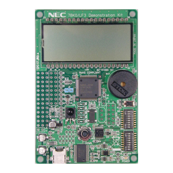
78K0/Lx3 - See it! 3. 78K0/Lx3 - See it! components The 78K0/Lx3 - See it! board is equipped with a navigation switch, a 224 segment LCD panel, temperature sensor and with several connectors in order to be connected to host computers, FLASH programmer or any external target hardware. -
Page 15: Configuration Switches Sw1 / Sw2
78K0/Lx3 - See it! 3.1 Configuration switches SW1 / SW2 The different operation modes of the 78K0/Lx3 - See it! board can be set by switches SW1 and SW2. Mode On-Board don’t care Debug FPL3 don’t care (WriteEZ3) QB-MINI2 don’t care Table 1: Operation mode selection SW1 / SW2 3.1.1 On-Board Debug Mode (TK-78 debugging) Within this mode On-Board debugging is enabled. -
Page 16: Reset Button, Sw4
78K0/Lx3 - See it! 3.2 RESET button, SW4 SW4 is the reset button. It activates the power on reset. It is connected to the reset input of the 78K0/LF3 microcontroller. 3.3 Navigation switch, SW3 Button SW3 is a navigation switch connected to the key interrupt port of the 78K0/LF3 device. It operates in five directions including a center push function. -
Page 17: External A/D Measurement Inputs, Connector J1
78K0/Lx3 - See it! 3.4 External A/D measurement inputs, connector J1 Connector J1 can be configured to measure external analogue signals by using the internal 10-Bit A/D converter or respectively the 16-bit ∆∑ A/D converter of the 78K0/LF3 device. To use this mode please open the corresponding soldering bridges A1 - A8. -
Page 18: Qb-Mini2 Connector, Ocd1
Connector OCD1 (not assembled) allows connecting the QB-MINI2 On-Chip debug emulator to the 78K0/Lx3 - See it! board in order to use On-Chip debug function of the 78K0/LF3 device. Please note, QB-MINI2 is a separate product from NEC and it is not included in this starterkit package. OCD1... -
Page 19: Usb Interface Connector, Usb1
Table 8: Pin Configuration of Connector USB1 For connection with the host machine, use a USB cable (Mini-B type). For confirmation, NEC Electronics used only the USB cable delivered with the 78K0/Lx3 - See it! board. User’s Manual U18759EE2V0UM00... -
Page 20: Lcd1, 224 Segment Lcd Panel
78K0/Lx3 - See it! 3.11 LCD1, 224 segment LCD panel The 78K0/Lx3 - See it! board is equipped with a 224 segment LCD panel. The LCD is a transflective model type operating at 5V supply voltage. It can operate at a eight times multiplex rate. The LCD driver specification is as following: LCD driver specification Mode... -
Page 21: Table 10: Lcd Segment Assignment
78K0/Lx3 - See it! LCD RAM address position bit7 ALARM MOON All FLASH (symbol) (symbol) 78K0/Lx3 bit6 bit5 bit4 bit3 bit2 bit1 bit0 LCD RAM address position bit7 Thur bit6 bit5 bit4 bit3 bit2 bit1 bit0 LCD RAM address positio bit7 (Battery) (Antenna) -
Page 22: External Lcd Resistors, Rr1 - Rr5
78K0/Lx3 - See it! 3.12 External LCD resistors, RR1 – RR5 The 78K0/Lx3 - See it! board can also be configured to use external voltage divider resistors for the generation of the LCD drive power supplies. For more details on the external resistance division method please refer to the user’s manual of the 78K0/LF3 device. -
Page 23: Connectors T1 - T13 And Wrap Field
78K0/Lx3 - See it! 3.17 Connectors T1 – T13 and wrap field Several pins of the 78K0/LF3 microcontroller are combined to the connectors T1 – T13. The corresponding assignment can be found in table below. Additional the 78K0/Lx3 - See it! board provides a wire wrap field area allowing the integration of additional application hardware. -
Page 24: Soldering Bridges
78K0/Lx3 - See it! 3.18 Soldering bridges Additional configuration of the 78K0/Lx3 - See it! board can be done by the soldering bridges A1 – A8 and V1 – V11. The different configuration modes are shown in the tables below. The soldering bridges A1 –... -
Page 25: 78K0/Lf3 Memory Map
78K0/Lx3 - See it! 3.19 78K0/LF3 memory map The memory layout of 78K0/LF3 device shown in the figure below. Figure 6: 78K0/LF3 memory map The 78K0/Lx3 - See it! does not reserve any resources of the 78K0/LF3 device, consequently all available memory of the device is free for application software. -
Page 26: On-Chip Debugging
78K0/Lx3 - See it! 4. On-Chip debugging The 78K0/Lx3 - See it! board offers two possibilities to use On-Chip debugging. The TK-78 debug function of 78K0/Lx3 - See it! allows On-Chip debugging without a need of external debug hardware. Within this mode the default USB / UART connection to the Host computer is used as debug interface. All standard debug functions are available in the On-Board debugging mode like FLASH programming / downloading, code execution, single stepping, breakpoints, memory manipulation etc. -
Page 27: Ocd Via Qb-Mini2 Emulator
78K0/Lx3 - See it! 4.2 OCD via QB-MINI2 emulator To operate the 78K0/Lx3 - See it! board together with the QB-MINI2 On-Chip debug emulator, configure switches SW1 and SW2 as following: Mode QB-MINI2 don’t care Table 15: Configuration for QB-MINI2 debugging Note: By supplying power from the QB-MINI2 do not connect external hardware to the 78K0/Lx3 - See it! board. -
Page 28: K0/Lx3 - See It! Installation And Operation
78K0/Lx3 - See it! 5. 78K0/Lx3 - See it! installation and operation 5.1 Getting started The IAR C-SPY debugger allows to download and debug application software on the 78K0/Lx3 - See it! starterkit hardware. Additionally the WriteEZ3 FLASH programming software can be used for simple FLASH programming of the 78K0/LF3 internal FLASH memory. -
Page 29: Hardware Installation
78K0/Lx3 - See it! 6. Hardware installation After unpacking 78K0/Lx3 - See it!, connect the board to your host computer using the provided USB interface cable. When 78K0/Lx3 - See it! is connected, the USB driver needs to be installed on the host machine. -
Page 30: Usb Driver Installation
78K0/Lx3 - See it! 7.4 USB Driver Installation In order to use the 78K0/Lx3 - See it! board for On-Chip debugging or FLASH programming, the USB driver needs to be installed on the host machine. Install the driver according to the following procedure: Installation on Windows 98SE/Me .. -
Page 31: Figure 10: Search Location Specification (Windows 98Se)
78K0/Lx3 - See it! Check the "Specify a location" check box only and enter "C:\Program Files\NECTools32\ WriteEZ3\DRIVER" in the address bar, then click Next>. Figure 10: Search Location Specification (Windows 98SE) <1> Check "Specify a location" only. <3> Click. <2> Enter "C:\Program Files\NECTools32\WriteEZ3\DRIVER". 備考... -
Page 32: Installation On Windows 2000
78K0/Lx3 - See it! When the window below is displayed, the installation of the USB driver is completed. Click Finish. The installation of the USB Serial Port driver is then automatically performed. Figure 12: Installation Completion (Windows 98SE) Click. 7.4.2 Installation on Windows 2000 When the 78K0/Lx3 - See it! board is connected with the host machine, the board is recognized by Plug and Play, and the wizard for finding new hardware is started. -
Page 33: Figure 14: Search Method 1 (Windows 2000)
78K0/Lx3 - See it! The window below is displayed. So, check that "Search for a suitable driver ..." is selected, then click Next>. Figure 14: Search Method 1 (Windows 2000) Check that "Search for a suitable driver ..." is selected. Click. -
Page 34: Figure 16: Address Specification 1 (Windows 2000)
78K0/Lx3 - See it! Enter "C:\Program Files\NECTools32\WriteEZ3\DRIVER" in the address bar, then click OK. Figure 16: Address Specification 1 (Windows 2000) Click. Enter "C:\Program Files\NECTools32\WriteEZ3\DRIVER". Remark If the installation destination folder is changed at the time of GUI software installation, enter "new-folder\WriteEZ3\DRIVER". -
Page 35: Figure 18: Usb Driver Installation Completion 1 (Windows 2000)
78K0/Lx3 - See it! Click Finish to complete the installation of the USB driver. Figure 18: USB Driver Installation Completion 1 (Windows 2000) Click. Proceed to the installation of the USB Serial Port driver. Click Next>. Figure 19: Found New Hardware Wizard 2 (Windows 2000) Click. -
Page 36: Figure 20: Search Method 2 (Windows 2000)
78K0/Lx3 - See it! The window below is displayed. So, check that "Search for a suitable driver ..." is selected, then click Next>. Figure 20: Search Method 2 (Windows 2000) Check that "Search for a suitable driver ..." is selected. Click. -
Page 37: Figure 22: Address Specification 2 (Windows 2000)
78K0/Lx3 - See it! 10. Enter "C:\Program Files\NECTools32\WriteEZ3\DRIVER" in the address bar, then click OK. Figure 22: Address Specification 2 (Windows 2000) Click. Enter "C:\Program Files\NECTools32\WriteEZ3\DRIVER". Remark If the installation destination folder is changed at the time of GUI software installation, enter "new-folder\DRIVER". -
Page 38: Installation On Windows Xp
78K0/Lx3 - See it! 12. Click Finish to complete the installation of the USB driver. Figure 24: USB Driver Installation Completion 2 (Windows 2000) Click. 7.4.3 Installation on Windows XP When the 78K0/Lx3 - See it! board is connected with the host machine, the board is recognized by Plug and Play, and the wizard for finding new hardware is started. -
Page 39: Figure 26: Search Location Specification 3 (Windows Xp)
78K0/Lx3 - See it! Check that "Search for the best driver in these locations." is selected. Check the "Include this location search:" check enter "C:\Program Files\NECTools32\WriteEZ3\DRIVER" in the address bar, then click Next>. Figure 26: Search Location Specification 3 (Windows XP) <1>... -
Page 40: Figure 28: Usb Driver Installation Completion 1 (Windows Xp)
78K0/Lx3 - See it! When the window below is displayed, the installation of the USB driver is completed. Click Finish. Figure 28: USB Driver Installation Completion 1 (Windows XP) Click. Proceed to the installation of the USB Serial Port driver. Click Next>. Figure 29: Found New Hardware Wizard 2 (Windows XP) Check that "Install from a list Click. -
Page 41: Figure 30: Search Location Specification 2 (Windows Xp)
78K0/Lx3 - See it! Check that "Search for the best driver in these locations." is selected. Check the "Include this location search:" check enter "C:\Program Files\NECTools32\WriteEZ3\DRIVER", then click Next>. Figure 30: Search Location Specification 2 (Windows XP) <1> Check that "Search for the best driver in these locations."... -
Page 42: Figure 32: Usb Serial Port2 Driver Installation Completion (Windows Xp)
78K0/Lx3 - See it! When the window below is displayed, the installation of the USB driver is completed. Click Finish. Figure 32: USB Serial Port2 Driver Installation Completion (Windows XP) Click. User’s Manual U18759EE2V0UM00... -
Page 43: Confirmation Of Usb Driver Installation
78K0/Lx3 - See it! 7.5 Confirmation of USB Driver Installation After installing the two types of drivers, check that the drivers have been installed normally, according to the procedure below. When using the 78K0/Lx3 - See it! board in combination with the IAR C-SPY debugger and the WriteEZ3 FLASH programming GUI, the information to be checked here is needed. -
Page 44: Driver Deinstallation
78K0/Lx3 - See it! 7.6 Driver deinstallation The driver deinstallation program is installed on the host machine when the WriteEZ3 software is installed. Use the procedure below for deinstall the USB driver. When using Windows XP, log on as the computer administrator. When using Windows 2000, log on as the Administrator. -
Page 45: Figure 36: Completion Of Driver Uninstallation
78K0/Lx3 - See it! Click Finish to complete driver uninstallation. Figure 36: Completion of Driver Uninstallation Click. Caution If the GUI software is uninstalled earlier, "Ftdiunin.exe" is also deleted. At this time, delete "USB Serial Port (COM?)" and "USB High Speed Serial Converter" from Device Manager manually. -
Page 46: Writeez3 Flash Programming Software
GUI, folder < WriteEZ3 install-path>\PRM. Nevertheless, newest version of parameter file for the μPD78F0495 device can by download from the NEC Electronics Web site. Download the parameter file for the PG-FP4 from the following NEC Electronics Web site: http://www.eu.necel.com/updates Copy the parameter file downloaded from the NEC Electronics Web site into sub-directory <WriteEZ3.EXE-install-path>\PRM created during GUI software setup (refer to CHAPTER 7... -
Page 47: Toolbar
78K0/Lx3 - See it! This window consists of the following items: Name Display Information Menu bar Displays menu items executable by the (displayed at the top) WriteEZ3. Toolbar Displays frequently used commands as (displayed under the menu bar) icons. Action log window Displays an WriteEZ3 action log. -
Page 48: Menu Bar
78K0/Lx3 - See it! 8.4 Menu Bar Depending on the actual device status and device type, some menu items may be enabled or disabled. 8.4.1 [File] menu Clicking the [File] menu displays the pull-down menu as shown below. This menu mainly contains commands related to file operation. Figure 39: [File] Menu [Load] command The [Load] command allows you to select a program file. -
Page 49: Device] Menu
78K0/Lx3 - See it! [Quit] command The [Quit] menu is the command for terminating the WriteEZ3 GUI software. Clicking × on the right side of the task bar also terminates the WriteEZ3 GUI software. Note User settings are saved in the WriteEZ3.INI file, so that the GUI software starts up next time with the same settings. - Page 50 78K0/Lx3 - See it! (3) [Program] command The [Program] command sends a specified user program to the target device and writes the program to the flash memory. The execution of Verify operation for detecting an error in user program communication from the WriteEZ3 to the target device after the execution of the [Program] command follows the setting of the 'Command options' on the Advance tab displayed by selecting [Device] →...
-
Page 51: Figure 42: Device Setup Window - Standard
78K0/Lx3 - See it! [Setup] command The [Setup] menu allows you to make settings related to flash memory rewriting according to the user environment and to set command options. Each time the GUI software is started, the most recently used parameter file (.PRM) is read and the settings are displayed. -
Page 52: Figure 43: Device Setup Window - Parameter File Selection
78K0/Lx3 - See it! <1> Parameter file This file holds parameters and timing data required to rewrite the flash memory of the target device. Do not modify the data in the parameter file because the data is related to the guarantee of rewrite data. The parameter file is protected by the checksum function. -
Page 53: Figure 45: Device Setup Window - Host Connection
78K0/Lx3 - See it! <2> Host connection "Host connection" is used to select a channel for communication between the 78K0/Lx3 – See it! board and host machine. Figure 45: Device Setup Window – Host connection [Port list box] Select a channel for communication between the 78K0/Lx3 – See it! board and host machine. -
Page 54: Figure 47: Device Setup Window - Operation Mode
78K0/Lx3 - See it! <4> Operation Mode The setting of "Operation Mode" may divide the flash memory of some target devices into blocks or areas. This menu is used to select an operation mode of the flash memory. Some devices do not have the block and area division modes, and some devices have only one of the modes. -
Page 55: Figure 49: Device Setup Window - Advance
78K0/Lx3 - See it! (b) Advance setup The Advance setup menu is used to specify the command options and security flag settings. When "Advance" is clicked, the following window is displayed: Figure 49: Device Setup Window - Advance <1> Command options This dialog box is used to specify the WriteEZ3 flash processing command options. -
Page 56: Figure 51: Device Setup Window - Security Flag Settings
78K0/Lx3 - See it! [Checksum after Program check box] If this check box is checked, the flash memory checksum value of the target device is read from the target device after execution of the Program command and EPV command. This value differs from the value displayed in the parameter window of the main window. -
Page 57: Figure 52: Device Setup Window - Disable Chip Erase
78K0/Lx3 - See it! [Disable Chip Erase check box] If this check box is checked, the [Erase] command becomes invalid in the entire flash memory area of the target device. At this time, the warning message shown below is displayed. Figure 52: Device Setup Window –... -
Page 58: View] Menu
78K0/Lx3 - See it! 8.4.3 [View] menu Clicking the [View] menu displays the pull-down menu shown below. This menu contains commands for setting whether to display the toolbar and status bar. Figure 54: [View] Menu [Toolbar] command Checking the [Toolbar] command displays the toolbar. Unchecking the command hides the toolbar. -
Page 59: Help] Menu
78K0/Lx3 - See it! 8.4.4 [Help] menu Clicking the [Help] menu displays the following pull-down menu: Figure 55: [Help] Menu [About WriteEZ3] command The [About WriteEZ3] command opens the program entry window as shown below and indicates the version. Clicking OK terminates the display. Figure 56: About WriteEZ3 Window User’s Manual U18759EE2V0UM00... -
Page 60: Programmer Parameter Window
78K0/Lx3 - See it! 8.5 Programmer Parameter Window This window displays the settings of the programming parameters. Figure 57: Programmer Parameter Window [Device] Updated after communication with the target device to display information about the target device. [Parameter file] Updated after [Setup] command execution to display information about a read parameter file. [Load file] Updated after [Load] command execution to select information about a selected program file. -
Page 61: How To Use Writeez3 Flash Programming Software
WriteEZ3 GUI, folder <WriteEZ3 install-path>\PRM. Nevertheless, newest version of parameter file for the μPD78F0495 device can by download from the NEC Electronics Web site. Download the parameter file for the PG-FP4 from the following NEC Electronics Web site: http://www.eu.necel.com/updates Copy the parameter file downloaded from the NEC Electronics Web site into sub-directory <WriteEZ3.EXE-install-path>\PRM created during GUI software setup (refer to CHAPTER 7... -
Page 62: Connecting And Starting
78K0/Lx3 - See it! Connecting and starting <1> Set the 78K0/Lx3 - See it! board to the WriteEZ3 FLASH programming mode by switching SW1 and SW2 to the following setting: Mode FPL3 don’t care (WriteEZ3) <2> <Plug and Play> Connect the 78K0/Lx3 - See it! board with the host machine via the USB cable. -
Page 63: Setting The Programming Environment
78K0/Lx3 - See it! <3> Start the WriteEZ3 GUI. Figure 58: GUI Software Startup Screen Setting the programming environment <1> Select [Device] → [Setup] from the menu bar. <2> The Standard dialog box for device setup is activated. Figure 59: <Standard Device Setup> Dialog Box User’s Manual U18759EE2V0UM00... -
Page 64: Figure 60: Parameter File Selection
78K0/Lx3 - See it! <3> Click PRM File Read to open the parameter file selection window. Select the parameter file “78F0495.prm” then click Open. Figure 60: Parameter File Selection <4> From the Port list box, select the communication port that matches the host machine being used. -
Page 65: Figure 62:
78K0/Lx3 - See it! <5> Set "Supply oscillator" according to the specifications of the 78K0/Lx3 - See it! board, “Frequency = 6.00 MHz” and “Multiply rate = 1.00”. In "Operation Mode", please specify the “Chip” mode. The following figure shows the recommended settings: Figure 62: <Standard Device Setup>...Dialog Box After Setting -
Page 66: Selecting A User Program
78K0/Lx3 - See it! <7> Click the OK button. The GUI software sets the parameters. When the settings have been completed, the following screen is displayed: Figure 64: Completion of Parameter Setting "PRM File Read OK." is displayed. The display is updated. Selecting a user program <1>... -
Page 67: [Autoprocedure(Epv)] Command Execution
78K0/Lx3 - See it! [Autoprocedure(EPV)] command execution Select [Device] → [Autoprocedure(EPV)] from the menu bar. When the [Autoprocedure(EPV)] command is executed, Blank Check → Erase → Program and FLASH Internal Verify are executed sequentially for the μPD78F0495 device. Figure 66: After EPV Execution "...finish"... -
Page 68: Troubleshooting
78K0/Lx3 - See it! 10. TROUBLESHOOTING In driver installation, recognition based on Plug and Play is disabled. Cause: The USB connector may not be inserted normally into the USB port of the personal computer. Action: Check that the USB connector is inserted fully into the USB port of the personal computer. Alternatively, disconnect the USB connector, then insert the USB connector again after a while. - Page 69 78K0/Lx3 - See it! Communication with the 78K0/Lx3 - See it! board is disabled. Cause: The driver may not be installed correctly. Action: Check if "USB Serial Port" and "USB High Speed Serial Converter" are installed correctly by referring to CHAPTER 7.5 USB Driver Installation. Cause: The COM port selected via the “Port list box”...
-
Page 70: Iar Sample Session
78K0/Lx3 - See it! 11. IAR sample session Before using the On-Board debug function of the 78K0/Lx3 - See it! board together with the IAR C-SPY debugger it is necessary to install the USB driver first. The communication between the starterkit and the IAR C-SPY debugger - that is running on the personal computer - is done via the standard UART / USB connection. -
Page 71: Figure 67: Iar Embedded Workbench
78K0/Lx3 - See it! When everything is set up correctly the IAR Embedded Workbench can be started. To do so, start the Embedded Workbench from Windows “Start” menu > “Programs” > folder “IAR Systems” > “IAR Embedded Workbench Kickstart for 78K”. The following screen appears: Figure 67: IAR Embedded Workbench Now select the option “Open exiting workspace”... -
Page 72: Figure 68: Iar Project Workspace
78K0/Lx3 - See it! After the demo workspace has been opened the projects contained in the workspace are displayed. Now select the “voltmeter” demo project within the workspace window. To do so, please use the pull down menu within the workspace window and select “Voltmeter – Debug”. Click on the little “+” sign next to the “Voltmeter”... -
Page 73: Figure 70: Iar Debugger Options 2/2
78K0/Lx3 - See it! Before using the On-Board debug function it is necessary to set the corresponding USB serial COM port of the host computer where the 78K0/Lx3 - See it! board is connected. To set the COM port, please select the category “TK-78”... -
Page 74: Figure 72: Tk-78 Hardware Setup Menu
78K0/Lx3 - See it! Now after everything has been setup correctly it’s time to compile and link the demonstration project. Close the Options menu and select “Rebuild All” from the “Project” menu. If the project is compiled and linked without errors it can now be downloaded to the 78K0/Lx3 - See it! board and debugged. To start the IAR C-SPY debugger select the option “Debug”... -
Page 75: Figure 73: Iar Project Download
78K0/Lx3 - See it! Now the debugger is started and the demo project is downloaded to the 78K0/Lx3 - See it! board. The progress of downloading is indicated by blue dots in the TK-78 Emulator window. Please note, downloading of larger executables can take some time. Figure 73: IAR project download User’s Manual U18759EE2V0UM00... -
Page 76: Figure 74: Iar C-Spy Debugger
78K0/Lx3 - See it! After the download was completed all debug features of IAR C-SPY debugger are available, i.e. Single Stepping (Step Over/-In/-Out), Go, Stop, Breakpoints, Register / Memory view etc. To get more details on the debugger configuration and capabilities please refer to the “78K IAR Embedded Workbench IDE User Guide”... -
Page 77: Sample Projects
78K0/Lx3 - See it! 12. Sample Projects Each of the sample programs is located in a single directory, which will be called main-directory of the sample. This main directory of a sample contains the complete project inclusive all output files of the development tool. -
Page 78: Buzzer Sample
See it! board. The output terminal of the IR receiver (type RPM7138) is connected to the remote control input pin P41/KR1/RIN of the 78K0/LF3 device. By running the sample, custom code and data code in the NEC format that is transmitted by an external remote controller can be received. The received data is displayed alternately 16-bit wise on the LCD panel. -
Page 79: Cables
78K0/Lx3 - See it! 13. Cables 13.1 USB interface cable (Mini-B type) Figure 75: USB interface cable (Mini-B type) User’s Manual U18759EE2V0UM00... -
Page 80: Schematics
78K0/Lx3 - See it! 14. Schematics Figure 76: 78K0/Lx3 - See it! schematics 1/2 User’s Manual U18759EE2V0UM00... -
Page 81: Figure 77: 78K0/Lx3 - See It! Schematics 2/2
78K0/Lx3 - See it! Figure 77: 78K0/Lx3 - See it! schematics 2/2 User’s Manual U18759EE2V0UM00... - Page 82 78K0/Lx3 - See it! [memo] User’s Manual U18759EE2V0UM00...