Huawei UPS5000-E Series User Manual
Hide thumbs
Also See for UPS5000-E Series:
- User manual (300 pages) ,
- Quick manual (20 pages) ,
- Quick manual (14 pages)

Related Manuals for Huawei UPS5000-E Series


Summary of Contents for Huawei UPS5000-E Series
- Page 1 Part Number: 31010RSV UPS5000-E-(20 kVA-160 kVA) User Manual (Low voltage) Issue Date 2020-04-27 HUAWEI TECHNOLOGIES CO., LTD.
- Page 2 Notice The purchased products, services and features are stipulated by the contract made between Huawei and the customer. All or part of the products, services and features described in this document may not be within the purchase scope or the usage scope. Unless otherwise specified in the contract, all statements, information, and recommendations in this document are provided "AS IS"...
-
Page 3: About This Document
Indicates a potentially hazardous situation which, if not avoided, could result in equipment damage, data loss, performance deterioration, or unanticipated results. NOTICE is used to address practices not related to personal injury. Issue 03 (2020-04-27) Copyright © Huawei Technologies Co., Ltd. - Page 4 Changes between document issues are cumulative. The latest document issue contains all the changes made in earlier issues. Issue 03 (2020-04-27) Updated the user interface. Issue 02 (2019-03-13) Updated the part number. Issue 01 (2017-02-17) This is the first release. Issue 03 (2020-04-27) Copyright © Huawei Technologies Co., Ltd.
-
Page 5: Table Of Contents
2.4.2.1 Overview ................................25 2.4.2.2 ECM................................25 2.4.2.3 Dry contact card .............................27 2.4.2.4 Monitoring interface card ..........................29 2.5 Typical Configurations............................34 2.5.1 Single UPS ................................34 2.5.2 1+1 Parallel System ............................34 2.5.3 Dual-Bus System ...............................35 Issue 03 (2020-04-27) Copyright © Huawei Technologies Co., Ltd. - Page 6 4.1.1 Main Menu ................................91 4.1.2 System Info Screen ............................92 4.1.2.1 Module Data Screen ............................93 4.1.2.2 Running ................................93 4.1.2.3 Alarms Screen..............................96 4.1.2.4 Settings................................98 4.1.2.5 Maintenance ..............................116 4.1.2.6 About Screen ..............................119 Issue 03 (2020-04-27) Copyright © Huawei Technologies Co., Ltd.
- Page 7 5.2 Shutting Down and Powering Off the UPS ......................171 5.3 Starting the UPS in Battery Mode ........................172 5.4 Transferring to Bypass Mode ..........................173 5.5 Setting ECO Mode ............................. 173 5.6 Testing Batteries ..............................174 Issue 03 (2020-04-27) Copyright © Huawei Technologies Co., Ltd.
- Page 8 8.5 Bypass Input Electrical Specifications ......................... 197 8.6 Battery Specifications ............................197 8.7 Output Electrical Specifications .......................... 198 8.8 System Electrical Specifications ......................... 198 A Alarm List ..........................200 B Acronyms and Abbreviations .................... 208 Issue 03 (2020-04-27) Copyright © Huawei Technologies Co., Ltd.
-
Page 9: Safety Information
The "NOTICE", "CAUTION", "WARNING", and "DANGER" statements in this document do not cover all the safety instructions. They are only supplements to the safety instructions. Huawei will not be liable for any consequence caused by the violation of general safety requirements or design, production, and usage safety standards. - Page 10 Keep irrelevant people away from the equipment. Only operators are allowed to access the equipment. Use insulated tools or tools with insulated handles, as shown in the following figure. Issue 03 (2020-04-27) Copyright © Huawei Technologies Co., Ltd.
- Page 11 To avoid electric shock, do not connect safety extra-low voltage (SELV) circuits to telecommunication network voltage (TNV) circuits. Issue 03 (2020-04-27) Copyright © Huawei Technologies Co., Ltd.
-
Page 12: Personnel Requirements
Do not power on the equipment before it is installed or confirmed by professionals. 1.2 Personnel Requirements Personnel who plan to install or maintain Huawei equipment must receive thorough training, understand all necessary safety precautions, and be able to correctly perform all operations. - Page 13 When selecting, connecting, and routing cables, follow local safety regulations and rules. The static electricity generated by human bodies may damage the electrostatic-sensitive components on boards, for example, the large-scale integrated (LSI) circuits. Issue 03 (2020-04-27) Copyright © Huawei Technologies Co., Ltd.
-
Page 14: Installation Environment Requirements
Ensure that the equipment room provides good heat insulation, and the walls and floor are dampproof. Install a rat guard at the door of the equipment room. Issue 03 (2020-04-27) Copyright © Huawei Technologies Co., Ltd. -
Page 15: Mechanical Safety
Before hoisting objects, ensure that hoisting tools are firmly secured onto a load-bearing object or wall. Ensure that the angle formed by two hoisting cables is no more than 90 degrees, as shown in the following figure. Issue 03 (2020-04-27) Copyright © Huawei Technologies Co., Ltd. - Page 16 Do not climb higher than the fourth rung of the ladder from the top. Ensure that your body's center of gravity does not shift outside the legs of the ladder. Issue 03 (2020-04-27) Copyright © Huawei Technologies Co., Ltd.
-
Page 17: Device Running Safety
Metal shavings from drilling may short-circuit boards inside the equipment. Obtain the consent from the customer, subcontractor, and Huawei before drilling. Wear goggles and protective gloves when drilling holes. ... - Page 18 Any operation on any electrical device in an environment that has inflammable air can cause extreme danger. Strictly obey the operating environmental requirements specified in related user manuals when using or storing the device. Issue 03 (2020-04-27) Copyright © Huawei Technologies Co., Ltd.
-
Page 19: Battery Safety
Move batteries in the required direction. Do not place a battery upside down or tilt it. Keep the battery loop disconnected during installation and maintenance. Use batteries of specified models. Using batteries of other models may damage the batteries. Issue 03 (2020-04-27) Copyright © Huawei Technologies Co., Ltd. - Page 20 The site must be equipped with qualified fire extinguishing facilities, such as firefighting sands and powder fire extinguishers. To ensure battery safety and battery management accuracy, use batteries provided with the UPS by Huawei. Huawei is not responsible for any battery faults caused by batteries not provided by Huawei. Battery Installation Before installing batteries, observe the following safety precautions: ...
- Page 21 Use batteries within the allowed temperature range; otherwise, the battery performance and safety will be compromised. Do not throw a lithium battery in fire. When maintenance is complete, return the waste lithium battery to the maintenance office. Issue 03 (2020-04-27) Copyright © Huawei Technologies Co., Ltd.
-
Page 22: Others
UPS output voltage level or frequency. Doing so may affect the power supply to equipment. Exercise caution when setting battery parameters. Incorrect settings will affect the power supply and battery lifespan. Issue 03 (2020-04-27) Copyright © Huawei Technologies Co., Ltd. -
Page 23: Overview
This document describes the following UPS models: UPS5000-E-60K-F60 Output capacity: 20 kVA, 40 kVA, or 60 kVA UPS5000-E-100K-F100 Output capacity: 20 kVA, 40 kVA, 60 kVA, 80 kVA, or 100 kVA UPS5000-E-160K-F160 Issue 03 (2020-04-27) Copyright © Huawei Technologies Co., Ltd. -
Page 24: Benefits
Ease of Use The UPS5000-E is maintained from the front. UPS5000-E-60K-F60 and UPS5000-E-100K-F100 can be installed back to back or in a row against the wall to save space. Issue 03 (2020-04-27) Copyright © Huawei Technologies Co., Ltd. -
Page 25: Working Principle
The UPS5000 uses the digital signal processing (DSP) technology for intelligent control. Its power module consists of a rectifier, inverter, and DC/DC converter. The UPS5000 converts inputs into pure high-quality sine wave outputs by using the high-frequency switching technology. Issue 03 (2020-04-27) Copyright © Huawei Technologies Co., Ltd. -
Page 26: Working Modes
In normal mode, the rectifier converts AC power into DC power, then the inverter converts DC power into high-precision AC outputs. The conversions protect loads from interference such as input harmonics, glitches, and voltage transients. Issue 03 (2020-04-27) Copyright © Huawei Technologies Co., Ltd. -
Page 27: Bypass Mode
The bypass power supply is not protected by the UPS which means it may be affected by mains outage, and incorrect AC voltage or frequency. Issue 03 (2020-04-27) Copyright © Huawei Technologies Co., Ltd. -
Page 28: Battery Mode
If the mains input is abnormal or the rectifier becomes abnormal, the UPS transfers to battery mode. The power module obtains DC power from batteries, and the power is converted into AC output by the inverter. Issue 03 (2020-04-27) Copyright © Huawei Technologies Co., Ltd. -
Page 29: Maintenance Bypass Mode
2.3.2.4 Maintenance Bypass Mode When the UPS works in maintenance bypass mode, the current flows through the maintenance bypass instead of the power module. You can maintain the circuit inside the cabinet. Issue 03 (2020-04-27) Copyright © Huawei Technologies Co., Ltd. -
Page 30: Eco Mode
ECO voltage range, the UPS transfers from bypass mode to normal mode. In bypass mode or normal mode, the rectifier keeps working and charges batteries using a charger. The ECO mode delivers a high efficiency. Issue 03 (2020-04-27) Copyright © Huawei Technologies Co., Ltd. - Page 31 2 Overview Figure 2-7 UPS conceptual diagram in ECO mode Manual startup is required to ensure that the inverter is in standby state and the power flow has reached the inverter. Issue 03 (2020-04-27) Copyright © Huawei Technologies Co., Ltd.
-
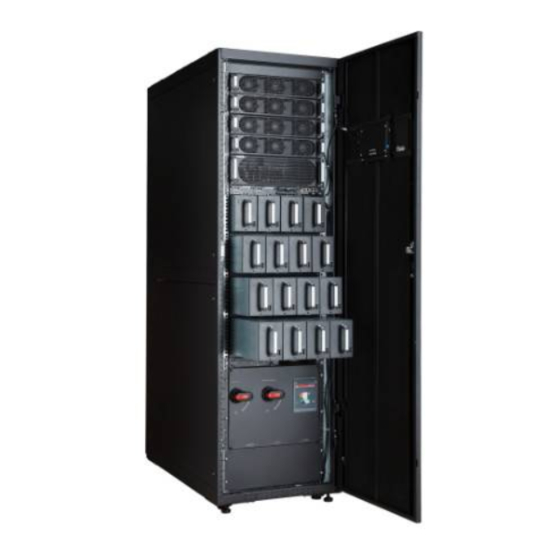
Page 32: Overview
(3) Maintenance (4) Power distribution unit (MDU) panels bypass switch subrack cover (5) Control Module (6) Bypass (7) Power modules (CM) module The UPS5000-E-160K-F160 cabinet is taken here as an example. Issue 03 (2020-04-27) Copyright © Huawei Technologies Co., Ltd. -
Page 33: Control Module
(17) Battery temperature (18) Optional card sensor port subrack cover Ports are protected by a security mechanism. 2.4.2.2 ECM Appearance The control module consists of two energy control modules (ECMs) in active/standby mode. Issue 03 (2020-04-27) Copyright © Huawei Technologies Co., Ltd. - Page 34 The ECM has no minor alarm or the software of the ECM is being upgraded. FAULT Steady on The ECM has a critical alarm. The ECM has no critical alarm or the software of the ECM is being upgraded. Issue 03 (2020-04-27) Copyright © Huawei Technologies Co., Ltd.
-
Page 35: Dry Contact Card
CAN communication, and inter-rack parallel CAN communication. Figure 2-11 Logical connections for CAN communication Specifications Hot-swappable 1 U high 2.4.2.3 Dry contact card Appearance Figure 2-12 Dry contact card Issue 03 (2020-04-27) Copyright © Huawei Technologies Co., Ltd. - Page 36 Port for signal ground circuit breaker STATUS_0V SWITCH Port for monitoring the Disconnected: Disconnected STATUS_MT maintenance circuit breaker circuit breaker ON Connected: circuit SWITCH Port for signal ground breaker OFF Issue 03 (2020-04-27) Copyright © Huawei Technologies Co., Ltd.
-
Page 37: Monitoring Interface Card
The monitoring interface card provides external ports as well as monitoring and control functions for the MDU. The ports include the ambient temperature and humidity sensor port, iBattery port, FE port, battery temperature monitoring port, and network management port. Issue 03 (2020-04-27) Copyright © Huawei Technologies Co., Ltd. - Page 38 Connects to an ambient temperature and humidity sensor over two wires. Southbound COM2 Supported protocol: Modbus-RTU. communications port 2 Connects to a southbound device, such as an iBattery. Issue 03 (2020-04-27) Copyright © Huawei Technologies Co., Ltd.
- Page 39 RS485 cables and FE cables must be shielded cables. Figure 2-14 Figure 2-15 are recommended wiring methods for DO ports. Figure 2-14 Wiring method 1 Figure 2-15 Wiring method 2 Issue 03 (2020-04-27) Copyright © Huawei Technologies Co., Ltd.
- Page 40 UPS5000-E-(20 kVA-160 kVA) User Manual (Low voltage) 2 Overview Figure 2-16 COM1 pins Table 2-6 COM1 pin definition Description RS485– RS485+ 12V_PORT Figure 2-17 COM2 pins Table 2-7 COM2 pin definition Description Issue 03 (2020-04-27) Copyright © Huawei Technologies Co., Ltd.
- Page 41 UPS5000-E-(20 kVA-160 kVA) User Manual (Low voltage) 2 Overview Description RS485+ RS485– RS485+ RS485– CANH0 CANL0 Figure 2-18 RS485 pins Table 2-8 RS485 pin definition Description RS485_T+ RS485_T– RS485_R+ RS485_R– Issue 03 (2020-04-27) Copyright © Huawei Technologies Co., Ltd.
-
Page 42: Typical Configurations
Energy control modules (ECMs) on each UPS are connected over parallel cables. The parallel connections synchronize the UPS outputs to supply power to loads. If one UPS fails, the other UPSs continue supplying power to loads. Issue 03 (2020-04-27) Copyright © Huawei Technologies Co., Ltd. -
Page 43: Dual-Bus System
BSC is a standard configuration. Of the two UPS systems, one is a master system, and the other is a slave system. The UPS systems work in normal mode or bypass mode. . Issue 03 (2020-04-27) Copyright © Huawei Technologies Co., Ltd. -
Page 44: Optional Components
Antiseismic kit Reinforces the cabinet so that the cabinet meets the requirements of 9 degree seismic fortification intensity. IP21 Prevents water from dropping into Issue 03 (2020-04-27) Copyright © Huawei Technologies Co., Ltd. - Page 45 The ECM extended subrack does not support onsite installation. If you require this optional component, inform Huawei when you purchase the UPS. Huawei installs it before delivery. Issue 03 (2020-04-27) Copyright © Huawei Technologies Co., Ltd.
-
Page 46: Installation
20 kVA 253 kg 40 kVA 285 kg 60 kVA 317 kg 80 kVA 359 kg 100 kVA 381 kg 120 kVA 413 kg 140 kVA 445 kg 160 kVA 477 kg Issue 03 (2020-04-27) Copyright © Huawei Technologies Co., Ltd. -
Page 47: Installation Environment
When no top outlet kit is added, keep a clearance of at least 500 mm from the rear of the cabinet. If you need to perform operations at the rear of the cabinet, keep a clearance of at least 800 mm. Issue 03 (2020-04-27) Copyright © Huawei Technologies Co., Ltd. -
Page 48: Tools And Instruments
Table 3-2 Tools and meters Tools and Meters Electric pallet truck Manual pallet truck Ladder Rubber mallet Hammer drill and Hand-held electric Alloy hole saw Heat gun drill bit Φ16 drill Issue 03 (2020-04-27) Copyright © Huawei Technologies Co., Ltd. - Page 49 Protective gloves Insulated gloves Insulation protective shoes discharge (ESD) gloves Torque screwdriver Cable cutter Brush Flat-head screwdriver (2–5 mm) Phillips screwdriver Insulated torque Heat shrink tubing Insulated adjustable wrench wrench (M3/M4/M5/M6/M (M6/M8/M12/M16) Issue 03 (2020-04-27) Copyright © Huawei Technologies Co., Ltd.
-
Page 50: Power Cables
2 x (4 2 x (4 2 x (4 x 50) x 70) x 70) x 95) x 95) cross-sectional area (mm N (If the voltage is non-linear, increase the cross-section Issue 03 (2020-04-27) Copyright © Huawei Technologies Co., Ltd. - Page 51 Table 3-4 Power cable connector requirements for the UPS5000-E-60 kVA and UPS5000-E-100 kVA Connector Connection Mode Bolt Type Bolt Hole Torque Diameter Mains input connector Crimped OT terminals 10.5 mm 26 N· m Issue 03 (2020-04-27) Copyright © Huawei Technologies Co., Ltd.
- Page 52 A/3P A/3P A/3P A/3P A/3P Table 3-7 Upstream input circuit breakers Model UPS Capacity Component Specifications Manufacturer UPS5000-E-60K 20 kVA Mains input circuit breaker T1N160 TMD -F60 R80 FFC 3P (recommended Issue 03 (2020-04-27) Copyright © Huawei Technologies Co., Ltd.
- Page 53 If multiple loads are connected, specifications for branch circuit breakers must not exceed the recommended specifications. The circuit breaker selection principle is to protect loads and cables, and the cascading principle is to realize specific protection. Issue 03 (2020-04-27) Copyright © Huawei Technologies Co., Ltd.
-
Page 54: Unpacking And Checking
Step 2 Check the UPS packing. Step 3 Hold the sliding plate steady. Cut and remove the binding tapes. Put down the sliding plate gently. Figure 3-3 Removing binding tapes Step 4 Remove packing materials. Issue 03 (2020-04-27) Copyright © Huawei Technologies Co., Ltd. - Page 55 Check that all fittings comply with the packing list. If some fittings are missing or do not comply with the packing list, record this information and contact your local Huawei office immediately. Step 7 Remove the L-shaped bracket that secures the cabinet and the pallet, and secure the sliding plate to the pallet by using the two M12 screws that were removed.
-
Page 56: Installing A Single Ups
Step 8 Raise the four anchor bolts to the highest position using an adjustable wrench. Figure 3-6 Raising anchor bolts Step 9 Push the cabinet along the sliding plate to the floor. ----End 3.2 Installing a Single UPS Issue 03 (2020-04-27) Copyright © Huawei Technologies Co., Ltd. -
Page 57: Installing The Cabinet
Step 2 Use a hammer drill to drill four holes for installing expansion bolts and then install four expansion bolts in the holes. Figure 3-8 shows the composition of an expansion bolt, and Figure 3-9 shows how to install an expansion bolt. Issue 03 (2020-04-27) Copyright © Huawei Technologies Co., Ltd. - Page 58 Partially tighten the expansion bolt and vertically insert it into the hole. Hit the expansion bolt using a rubber mallet until the expansion sleeve is fully inserted into the hole. Partially tighten the expansion bolt. Remove the bolt, spring washer, and flat washer. Issue 03 (2020-04-27) Copyright © Huawei Technologies Co., Ltd.
- Page 59 Step 5 Remove the rear panel of the cabinet, and then open the front door. Figure 3-10 Removing the rear panel Step 6 Remove the four plugs from the bottom of the cabinet (two at the front and two at the rear). Issue 03 (2020-04-27) Copyright © Huawei Technologies Co., Ltd.
- Page 60 Step 1 Adjust the four anchor bolts at the bottom of the UPS cabinet until all the four castors at the bottom hang in the air and the anchor bolts bear all of the cabinet weight, as shown in Figure 3-13. Issue 03 (2020-04-27) Copyright © Huawei Technologies Co., Ltd.
-
Page 61: Installing Batteries
Step 1 Install a battery rack and batteries. For details, see the battery installation guide delivered along with the batteries. Step 2 (Optional) Install a BMU. For details, see the UPS Battery Monitor Unit User Manual. ----End Issue 03 (2020-04-27) Copyright © Huawei Technologies Co., Ltd. -
Page 62: Installing Optional Components
Step 2 Drill holes for installing expansion bolts, and install expansion bolts. Step 3 Secure two antiseismic kits to the front and rear of the cabinet: (With a marking-off template) use twelve M5x16 and four M12 screws. Issue 03 (2020-04-27) Copyright © Huawei Technologies Co., Ltd. - Page 63 Step 6 Secure antiseismic kits to the floor at both the front and rear of the cabinet by using eight M12 expansion bolts. The positioning is shown in Figure 3-17. Issue 03 (2020-04-27) Copyright © Huawei Technologies Co., Ltd.
-
Page 64: Installing An Ip21 Component
Select the mounting holes for leveling feet based on the cabinet width onsite. Figure 3-18 Installing leveling feet Step 2 Secure the IP21 component to the top of each cabinet using four M12 screws. Issue 03 (2020-04-27) Copyright © Huawei Technologies Co., Ltd. -
Page 65: Installing A Top Outlet Kit
Step 3 Pull the marked cable out of the cabinet, cut the cable from the marked position, strip the cable, and crimp a terminal. Issue 03 (2020-04-27) Copyright © Huawei Technologies Co., Ltd. -
Page 66: Routing Cables (60 Kva, 100 Kva)
Step 1 Ensure the maintenance bypass switch is OFF. Open the front door, and remove the cover from the power distribution subrack, as shown in Figure 3-21. The positioning of the copper bars is shown in Figure 3-22 Issue 03 (2020-04-27) Copyright © Huawei Technologies Co., Ltd. - Page 67 Figure 3-22 Copper bar positions (1) Battery input terminals (+, (2) Mains input terminals (3) Maintenance bypass N, –) (1L1–1L3, N) switch (4) Bypass input terminals (5) Output terminals (U, V, Issue 03 (2020-04-27) Copyright © Huawei Technologies Co., Ltd.
- Page 68 Step 2 Remove the cable covers from the top of the cabinet. Figure 3-23 Removing the cable covers from the top of the cabinet Step 3 Connect ground cables, as shown in Figure 3-24. Issue 03 (2020-04-27) Copyright © Huawei Technologies Co., Ltd.
- Page 69 : Internal equipotential connection : Protection ground Step 4 Route power cables. Dual mains Remove the copper bars between mains and bypass input terminals, as shown in Figure 3-25. Issue 03 (2020-04-27) Copyright © Huawei Technologies Co., Ltd.
- Page 70 Route a neutral wire from the middle of the positive and negative battery strings. The battery neutral wire is routed from the middle of positive and negative battery strings, each consisting of 20 batteries. Issue 03 (2020-04-27) Copyright © Huawei Technologies Co., Ltd.
- Page 71 Step 5 Route the signal cables on the left side of subracks along the left side of the cabinet and the cables on the right side of subracks along the right side of the cabinet, and then bind the cables to the cabinet, as shown in Figure 3-28. Issue 03 (2020-04-27) Copyright © Huawei Technologies Co., Ltd.
-
Page 72: Bottom Cable Routing
Context Route cables for the UPS from inside out. Procedure Step 1 Open the front door and remove the cover from the power distribution subrack. Step 2 Determine the cabling mode. Issue 03 (2020-04-27) Copyright © Huawei Technologies Co., Ltd. - Page 73 Remove all the cable cover for signal cables and small covers from the bottom. Remove the two large covers from the top of the cabinet, drill holes into them, and install them to the positions where the small covers were originally. Issue 03 (2020-04-27) Copyright © Huawei Technologies Co., Ltd.
- Page 74 The quantity of holes in the above figure is for reference only. If holes are drilled for routing cables, attach grommet strips on the hole edges to protect cables. Step 3 Connect ground cables. Issue 03 (2020-04-27) Copyright © Huawei Technologies Co., Ltd.
- Page 75 Step 4 Route power cables. Dual mains Remove the copper bars between mains and bypass input terminals. Figure 3-32 shows power cables routed from the bottom by removing small covers, as an example. Issue 03 (2020-04-27) Copyright © Huawei Technologies Co., Ltd.
- Page 76 Route a neutral wire from the middle of the positive and negative battery strings. The battery neutral wire is routed from the middle of positive and negative battery strings, each consisting of 20 batteries. Issue 03 (2020-04-27) Copyright © Huawei Technologies Co., Ltd.
- Page 77 Figure 3-34. Figure 3-34 Connecting signal cables The number and colors of signal cables in Figure 3-34 are for reference only. ----End Issue 03 (2020-04-27) Copyright © Huawei Technologies Co., Ltd.
-
Page 78: Routing Cables (160 Kva)
If you choose to route cables by drilling holes, paste grommet strip to the hole edge to protect cables. Step 5 Install the connecting kit on the UPS. Combine the UPS and the top entry cabinet by using a connecting kit. Issue 03 (2020-04-27) Copyright © Huawei Technologies Co., Ltd. - Page 79 UPS5000-E-(20 kVA-160 kVA) User Manual (Low voltage) 3 Installation Figure 3-35 Combining the UPS and the top entry cabinet Step 6 Short-circuit the UPS and the top entry cabinet using a parallel busbar. Issue 03 (2020-04-27) Copyright © Huawei Technologies Co., Ltd.
- Page 80 UPS5000-E-(20 kVA-160 kVA) User Manual (Low voltage) 3 Installation Figure 3-36 Installing a parallel busbar Step 7 Connect power cables to the UPS through the top entry cabinet. Issue 03 (2020-04-27) Copyright © Huawei Technologies Co., Ltd.
- Page 81 (2) Bypass input power (3) Mains input power (4) Output power cable cable cable cable Step 8 Connect signal cables to the UPS5000-E through the cable trough in the top entry cabinet. Issue 03 (2020-04-27) Copyright © Huawei Technologies Co., Ltd.
-
Page 82: Bottom Cable Routing
Route cables for the UPS from inside out. Procedure Step 1 Open the front door, and remove the cover from the power distribution subrack, as shown in Figure 3-39. Figure 3-40 shows the positions of copper bars. Issue 03 (2020-04-27) Copyright © Huawei Technologies Co., Ltd. - Page 83 (+, N, –) (2L1–2L3, N) (1L1–1L3, N) (4) Output terminals (U, V, (5) Maintenance bypass W, and N) switch Step 2 Determine the cabling mode. Remove small covers for routing cables. Issue 03 (2020-04-27) Copyright © Huawei Technologies Co., Ltd.
- Page 84 Remove the two large covers from the top of the cabinet, drill holes into them, and install them to the positions where the small covers were originally. Figure 3-42 Hole positions Issue 03 (2020-04-27) Copyright © Huawei Technologies Co., Ltd.
- Page 85 : Internal equipotential connection : Protection ground Step 4 Route power cables. Dual mains Remove the copper bars between the mains and bypass input terminals, as shown in Figure 3-44. Issue 03 (2020-04-27) Copyright © Huawei Technologies Co., Ltd.
- Page 86 UPS5000-E-(20 kVA-160 kVA) User Manual (Low voltage) 3 Installation Figure 3-44 Removing copper bars Figure 3-45 shows the power cables routed from the bottom of the cabinet. Issue 03 (2020-04-27) Copyright © Huawei Technologies Co., Ltd.
- Page 87 Route a neutral wire from the middle of the positive and negative battery strings. The battery neutral wire is routed from the middle of positive and negative battery strings, each consisting of 20 batteries. Issue 03 (2020-04-27) Copyright © Huawei Technologies Co., Ltd.
- Page 88 Figure 3-47. Figure 3-47 Connecting signal cables The number and colors of signal cables in Figure 3-47 are for reference only. ----End Issue 03 (2020-04-27) Copyright © Huawei Technologies Co., Ltd.
-
Page 89: Remote Epo
3 Installation 3.2.7 Remote EPO Huawei does not provide the EPO switch or cable. If the cable is required, the recommended cable is 22 AWG. Equip the EPO switch with a protective cover to prevent misoperations, and cover the cable with protective tubing. -
Page 90: Connecting Communications Cables
Step 1 Install the UPSs in a parallel system using the single UPS installation methods. Step 2 Unscrew the parallel plate and put it through the reserved holes to connect the two UPSs and then tighten the screws on the plate. Issue 03 (2020-04-27) Copyright © Huawei Technologies Co., Ltd. -
Page 91: Connecting Power Cables
Step 3 Connect battery cables to each UPS in the parallel system. Step 4 Select a parallel connection method to connect cables to the parallel system based on the site configurations. Issue 03 (2020-04-27) Copyright © Huawei Technologies Co., Ltd. - Page 92 Figure 3-51 Conceptual diagram of a 1+1 parallel system Figure 3-52 Cable connections for a 1+1 parallel system (1) Mains input power (2) Bypass input power (3) Battery (4) Output power cables cables cables cables Issue 03 (2020-04-27) Copyright © Huawei Technologies Co., Ltd.
- Page 93 User Manual (Low voltage) 3 Installation Figure 3-53 Figure 3-54 show the conceptual diagram and cable connections for a dual-bus system consisting of two UPS systems. Figure 3-53 Conceptual diagram of a dual-bus system Issue 03 (2020-04-27) Copyright © Huawei Technologies Co., Ltd.
-
Page 94: Connecting Signal Cables
Step 1 Connect the parallel ports on the UPSs in the parallel system over parallel cables. Figure 3-55 Figure 3-56 show the topology diagram and cable connections for the 1+1 parallel system. Issue 03 (2020-04-27) Copyright © Huawei Technologies Co., Ltd. - Page 95 Figure 3-56 Connecting signal cables in a parallel system consisting of two UPSs Connect cables to BSC ports in the UPS systems. Figure 3-57 shows how to connect signal cables in a dual-bus system. Issue 03 (2020-04-27) Copyright © Huawei Technologies Co., Ltd.
-
Page 96: Installation Verification
Acceptance Criteria UPS installation The UPS is securely installed and does not tilt due to vibration. Neat arrangement The UPS and its adjacent cabinets are neatly arranged and secured with connecting plates. Issue 03 (2020-04-27) Copyright © Huawei Technologies Co., Ltd. - Page 97 3. There is no foreign matter around switch terminals. 4. There is no foreign matter on the bottom plate of the cabinet. 5. There is no foreign matter on the rear module subrack. Issue 03 (2020-04-27) Copyright © Huawei Technologies Co., Ltd.
- Page 98 3. Do not remove the dustproof cover before power-on to prevent dust inside the UPS. Figure 3-58 Fill the holes with sealing putty (1) Paper protective film (2) Sealing putty Figure 3-59 Dustproof cover Issue 03 (2020-04-27) Copyright © Huawei Technologies Co., Ltd.
-
Page 99: User Interface
The LCD screen is divided into three parts: status bar, alarm bar and information area. Figure numerically labels functions of the default main screen, and Table 4-1 describes these functions. Figure 4-1 Main Menu screen Table 4-1 Main screen description Number Area Function Issue 03 (2020-04-27) Copyright © Huawei Technologies Co., Ltd. -
Page 100: System Info Screen
Returns to the upper-level menu. Logs a user out. 4.1.2 System Info Screen On the main screen, tap System Info. The System Info screen is displayed, as shown in Figure 4-2. Issue 03 (2020-04-27) Copyright © Huawei Technologies Co., Ltd. -
Page 101: Module Data Screen
Figure 4-3. Figure 4-3 Module Data screen 4.1.2.2 Running On the System Info screen, tap to access the Runn Info screen. Issue 03 (2020-04-27) Copyright © Huawei Technologies Co., Ltd. - Page 102 AC output frequency Power factor Proportion of output active power to output apparent power. Table 4-4 UPS load Item Description Active power (kW) Output active power of each phase on the UPS. Issue 03 (2020-04-27) Copyright © Huawei Technologies Co., Ltd.
- Page 103 Bypass input line voltage Phase current (A) Bypass input phase current Frequency (Hz) Bypass input frequency Power factor Proportion of the bypass input active power to the bypass input apparent power. Issue 03 (2020-04-27) Copyright © Huawei Technologies Co., Ltd.
-
Page 104: Alarms Screen
Humidity measured by the ambient temperature and humidity sensor. If the sensor is not installed, N/A is displayed. 4.1.2.3 Alarms Screen on the System Info screen to enter the Alarms screen. Issue 03 (2020-04-27) Copyright © Huawei Technologies Co., Ltd. - Page 105 This screen displays alarm information including the severity, name, ID, location, and generation time. Figure 4-7 Active alarms Historical alarms This screen displays alarm information including the severity, name, ID, location, generation time, and clear time. Figure 4-8 Historical alarms Issue 03 (2020-04-27) Copyright © Huawei Technologies Co., Ltd.
-
Page 106: Settings
If the buzzer is enabled, Buzzer Off is displayed on the operation screen. 4.1.2.4 Settings On the System Info screen, tap to access the Settings screen. Figure 4-9 Settings 1 Figure 4-10 Settings 2 Issue 03 (2020-04-27) Copyright © Huawei Technologies Co., Ltd. - Page 107 UPS5000-E-(20 kVA-160 kVA) User Manual (Low voltage) 4 User Interface Communication Settings Figure 4-11 Communication settings 1 Figure 4-12 Communication settings 2 Figure 4-13 IP settings IP address allocation Issue 03 (2020-04-27) Copyright © Huawei Technologies Co., Ltd.
- Page 108 Subnet mask Specifies the subnet mask of the 255.255.255.0 0.0.0.0–255.255. Ethernet. 255.255 Gateway Specifies the Ethernet gateway. 192.168.0.1 1.0.0.0–223.255. 255.255 MAC address Defines the physical address of network equipment and is not Issue 03 (2020-04-27) Copyright © Huawei Technologies Co., Ltd.
- Page 109 When the UPS is connected over the serial port Modbus, set this parameter based on the frame format that the upstream device Modbus supports. Northbound Set Northbound protocol type. ModbusRTU ModbusRTU, protocol type Issue 03 (2020-04-27) Copyright © Huawei Technologies Co., Ltd.
- Page 110 Figure 4-16 Ambient temperature and humidity sensor Item Description Default Value Value Range Start address 32–44 Quantity Number of cascaded ambient 0–4 temperature and humidity sensors Issue 03 (2020-04-27) Copyright © Huawei Technologies Co., Ltd.
- Page 111 Default Value Value Range Start address 16–28 Quantity Number of cascaded battery 0–4 temperature sensors Figure 4-18 BMU Item Description Default Value Value Range Start address Quantity Number of cascaded BMUs 0–12 Issue 03 (2020-04-27) Copyright © Huawei Technologies Co., Ltd.
- Page 112 WiFi device to which the mobile phone is connected. Password The password for accessing Changeme WiFi. Figure 4-20 SSH Settings Item Description Default Value Value Range Allowing or forbidding SSH Enable Disable, Enable login. Issue 03 (2020-04-27) Copyright © Huawei Technologies Co., Ltd.
- Page 113 UPS5000-E-(20 kVA-160 kVA) User Manual (Low voltage) 4 User Interface System Settings Figure 4-21 System settings 1 Figure 4-22 System settings 2 Figure 4-23 System settings 3 Item Description Default Value Value Range Issue 03 (2020-04-27) Copyright © Huawei Technologies Co., Ltd.
- Page 114 BSC-related hardware is properly installed. ≤ 1000 ≤ 1000, Altitude (m) Set this parameter based on the altitude of the place where the 1000–2000, rack is used. 2000–3000, 3000–4000, 4000–5000 Issue 03 (2020-04-27) Copyright © Huawei Technologies Co., Ltd.
- Page 115 BCB trips if Indicates whether the BCB trips Enable Disable, Enable UPS stops when the system stops supplying power supply power and the output power is off. Issue 03 (2020-04-27) Copyright © Huawei Technologies Co., Ltd.
- Page 116 Input cur. Specifies whether to enable or Enable Disable, Enable limiting disable input current limiting to protect generators. Input cur. Limits the input current to protect 50–200 the D.G. limiting ratio Issue 03 (2020-04-27) Copyright © Huawei Technologies Co., Ltd.
- Page 117 (less than 20 ms) occurs when the UPS transfers from normal mode to bypass mode. If Output freq. track rate (Hz/s) is fast, the Issue 03 (2020-04-27) Copyright © Huawei Technologies Co., Ltd.
- Page 118 ± 0.5 to ± 6 frequency bypass input frequency and the range (Hz) rated frequency is greater than the specified value, the system determines that the bypass frequency is abnormal, so the bypass is unavailable. Issue 03 (2020-04-27) Copyright © Huawei Technologies Co., Ltd.
- Page 119 2 V. A battery is a module consisting of single or multiple cells in a shell. Each battery has a nominal voltage of 2 V, 6 V, or 12 V. Figure 4-27 Battery settings 1 Figure 4-28 Battery settings 2 Issue 03 (2020-04-27) Copyright © Huawei Technologies Co., Ltd.
- Page 120 Cell equalized Specifies the battery equalized 2.35 2.30 to 2.40 volt. (V/cell) charging voltage. Dis. cur. 0.1C Specifies the EOD threshold 1.80 1.8–1.9 EOD (V/cell) when the discharging current is Issue 03 (2020-04-27) Copyright © Huawei Technologies Co., Ltd.
- Page 121 Dry contact extended card (MUE07A): provides five routes of input signals and five routes of output signals. Item Description MUE05A connection Specifies the MUE05A connection status. Independent input signals can be enabled only when this parameter is set to Enable. Issue 03 (2020-04-27) Copyright © Huawei Technologies Co., Ltd.
- Page 122 MUE07A DO_3 Action, MUE07A DO_4 Action, MUE07A DO_5 Action MUS05A DO_1, MUS05A Corresponds to the signal of the output dry contact DO on the MUS05A. DO_2, MUS05A DO_3, Issue 03 (2020-04-27) Copyright © Huawei Technologies Co., Ltd.
- Page 123 If the password complexity check is enabled, the password is required to be a string of 6–20 characters and contain at least two types of Issue 03 (2020-04-27) Copyright © Huawei Technologies Co., Ltd.
-
Page 124: Maintenance
Time Zone Figure 4-31 Time zone Set the local time zone. 4.1.2.5 Maintenance On the System Info screen, tap to display the Maintenance screen. Figure 4-32 Maintenance 1 Battery Maint. screen Issue 03 (2020-04-27) Copyright © Huawei Technologies Co., Ltd. - Page 125 You can export Fault Data, and perform Upgrade Software, BSP Upgrade, Export Config., and Import Config. with USB. Multi-brand is used to import the brand information of a partner to the corresponding WebUI. Issue 03 (2020-04-27) Copyright © Huawei Technologies Co., Ltd.
- Page 126 Wizard Startup The wizard startup can be used to test the bypass, mains inverter, inverter/bypass switch, battery inverter, battery charging capability, battery switch tripping and so on. Perform operations as prompted. Issue 03 (2020-04-27) Copyright © Huawei Technologies Co., Ltd.
-
Page 127: About Screen
On the System Info screen, tap About to view the UPS model, manufacturer name, monitoring version and power version, as shown in Figure 4-36. To view version details, tap Version Info. Issue 03 (2020-04-27) Copyright © Huawei Technologies Co., Ltd. -
Page 128: System Status
User Manual (Low voltage) 4 User Interface Figure 4-36 About screen 4.1.3 System Status On the System Status to view the mains input, bypass input, load, and battery information. Figure 4-37 System status Issue 03 (2020-04-27) Copyright © Huawei Technologies Co., Ltd. -
Page 129: Common Functions
User interfaces displayed correspond to the MDU version V100R003C01SPC530 and are for reference only. 4.2.1 Login Context Internet Explorer 11 is used as the example browser. The system supports Internet Explorer 11 and Firefox 31.0. Issue 03 (2020-04-27) Copyright © Huawei Technologies Co., Ltd. - Page 130 (common user) system information, starts/shuts down the inverter, rectifies faults, and controls the buzzer. Other control and maintenance functions that may affect system operation are invisible and parameters cannot be set. Issue 03 (2020-04-27) Copyright © Huawei Technologies Co., Ltd.
-
Page 131: Home
View the active alarms of the system. 4.2.3 Monitoring On the Monitoring page, you can view the running information, including UPS system, Bypass, Module Summary, ECM Summary, Battery, and battery group summary. Issue 03 (2020-04-27) Copyright © Huawei Technologies Co., Ltd. - Page 132 (° C) this parameter. –10 –20 to 0 Low ambient An alarm is generated when the temperature ambient temperature is lower than the Issue 03 (2020-04-27) Copyright © Huawei Technologies Co., Ltd.
- Page 133 If this parameter is set to Disable, regular check is disabled. If this parameter is set to Enable, one Disable Disable, Collect waveform can be stored manually. Enable real-time site waveform Issue 03 (2020-04-27) Copyright © Huawei Technologies Co., Ltd.
- Page 134 This parameter specifies the number of transfers between bypass mode and normal mode within 1 hour, which ensures system security. Issue 03 (2020-04-27) Copyright © Huawei Technologies Co., Ltd.
- Page 135 Enable, the power module detection (power unit) performs inverter capacitor fault detection based on the settings of Capacitor failure detection upper limit and Capacitor failure detection lower limit. If the power module Issue 03 (2020-04-27) Copyright © Huawei Technologies Co., Ltd.
- Page 136 ECO bypass mode. Battery Battery parameter settings impact battery maintenance, battery lifespan, and UPS discharge time. When you set battery parameters, note the following: Issue 03 (2020-04-27) Copyright © Huawei Technologies Co., Ltd.
- Page 137 After batteries transfer from 30–180 Scheduled equalized equalized charging to float charging charging, if the batteries do not interval (d) discharge, equalized charging starts only after the float charging Equalized 0–15 time reaches Equalized Issue 03 (2020-04-27) Copyright © Huawei Technologies Co., Ltd.
- Page 138 Single batt. 10–30 voltage. When a value exceeds dis. voltage the specified range, an alarm is deviation generated. alarm thres. The calculation formula is (Charge/Discharge voltage – Average voltage)/Average Issue 03 (2020-04-27) Copyright © Huawei Technologies Co., Ltd.
- Page 139 If an output dry contact is set to 1.70 1.70–2.10 Thres. of low Batt. Volt. Below Threshold, batt. volt. over and the battery voltage is lower dry contact (V/cell) than this threshold, the output dry Issue 03 (2020-04-27) Copyright © Huawei Technologies Co., Ltd.
-
Page 140: Query
Export Historical Alarm, Active Alarm, Operation Log, and Performance Data. 4.2.5 System Settings On the System Settings page, you can set Site Configuration, Time, IP Address, NetEco, ModbusTCP, Alarm Parameters, SNMP, Event Notice, and Outbox configuration. Issue 03 (2020-04-27) Copyright © Huawei Technologies Co., Ltd. - Page 141 Select the network security Upload the key of the network security certificate. certificate key to be uploaded Export certificate file: Export the root certificate. Time Set the time zone and time for the site. Issue 03 (2020-04-27) Copyright © Huawei Technologies Co., Ltd.
- Page 142 Mailbox Settings: Set the email address of the recipient in Mailbox Settings. Alarm Notification, set Alarm notification delay in Alarm Notification Parameter Settings, set Time of the first reminder and Interval in Alarm Reminder Issue 03 (2020-04-27) Copyright © Huawei Technologies Co., Ltd.
-
Page 143: Maintenance
4.2.6 Maintenance On the Maintenance page, you can perform Soft Upgrade and User Management, query Version Information, query and export E-label, export Fault Information, and import and back up Configuration File. Issue 03 (2020-04-27) Copyright © Huawei Technologies Co., Ltd. -
Page 144: Old Webui
4.3 Old WebUI User interfaces displayed in this document correspond to the WebUI version V100R001C35SPC001 and are for reference only. 4.3.1 Login Context Internet Explorer 11 is used as the example browser. Issue 03 (2020-04-27) Copyright © Huawei Technologies Co., Ltd. - Page 145 Changeme Only browses the system running information, exports (common user) system information, starts/shuts down the inverter, rectifies faults, and controls the buzzer. Other control Issue 03 (2020-04-27) Copyright © Huawei Technologies Co., Ltd.
-
Page 146: Monitoring
----End 4.3.2 Monitoring Figure 4-47 Monitoring If NA is displayed for load ratio, the value is invalid or outside the range. Table 4-22 Monitoring details Number Area Function Issue 03 (2020-04-27) Copyright © Huawei Technologies Co., Ltd. -
Page 147: Parameter Settings
Disable to Enable, check that the EPO cable is connected correctly. Bus capa. life If this parameter is set to Enable, Disable Disable, Enable the UPS detects the bus capacitor Issue 03 (2020-04-27) Copyright © Huawei Technologies Co., Ltd. - Page 148 BCB trips in If this parameter is set to Enable, Enable Disable, Enable case of EOD the BCB will trip in case of EOD. Input Settings Item Description Default Value Value Range Issue 03 (2020-04-27) Copyright © Huawei Technologies Co., Ltd.
- Page 149 Monitors the current differences Disable Disable, Enable detection between racks or modules. If this parameter is set to Enable, the Mod. Cur. Eql. Data can be viewed on the running information screen. Issue 03 (2020-04-27) Copyright © Huawei Technologies Co., Ltd.
- Page 150 Capacitor failure detection lower limit. If the power module determines that the inverter capacitor is faulty, it shuts down the inverter to prevent the fault from expanding. Issue 03 (2020-04-27) Copyright © Huawei Technologies Co., Ltd.
- Page 151 If this parameter is set to Enable, Enable Disable, Enable temp. comp. the float voltage is calibrated based on the battery temperature when a battery temperature sensor is connected. The parameter is configurable in any mode. Issue 03 (2020-04-27) Copyright © Huawei Technologies Co., Ltd.
- Page 152 Max. batt. dis. Set the maximum battery 0–48 time (h) discharge time. When the discharge time reaches this value, the UPS powers off. The battery discharge time can be set only to Issue 03 (2020-04-27) Copyright © Huawei Technologies Co., Ltd.
- Page 153 Remain. cap. An alarm is generated if this Disable Disable, Enable warning parameter is set to Enable and the remaining capacity is less Issue 03 (2020-04-27) Copyright © Huawei Technologies Co., Ltd.
-
Page 154: Communication Settings
Batt. Volt. Below Threshold, dry contact and the battery voltage is lower (V/cell) than this threshold, the output dry contact will output signals. 4.3.2.2 Communication Settings Figure 4-49 Communication settings Issue 03 (2020-04-27) Copyright © Huawei Technologies Co., Ltd. -
Page 155: Control
On the Logs page, you can set Log to Historical logs, Cap. test logs, or Common test logs, and query or export logs. Historical logs can be exported but not queried. Issue 03 (2020-04-27) Copyright © Huawei Technologies Co., Ltd. -
Page 156: Config
If the password complexity check is enabled, the user password is required to be a string of 6–20 characters and contain at least two types of characters. 4.3.4.2 Site Config. On the home page, choose Config. > Site Config. Issue 03 (2020-04-27) Copyright © Huawei Technologies Co., Ltd. - Page 157 Test to check whether the test email can be received. Configure Alarm Notification Server is used to configure a server for receiving alarm emails from the monitoring system. Issue 03 (2020-04-27) Copyright © Huawei Technologies Co., Ltd.
-
Page 158: Rccmd
Enable upon first login. After you submit the setting, the page refreshes. The controls such as SSL Encrypted Transmission and Event Configuration will be displayed on the page, as shown in Figure 4-56. Figure 4-55 RCCMD function disabled Issue 03 (2020-04-27) Copyright © Huawei Technologies Co., Ltd. - Page 159 Disable, the RCCMD certificate controls will not be displayed on the page, as shown in Figure 4-58. If SSL Encrypted Transmission is set to Disable, a message indicating there is a risk will be displayed. Issue 03 (2020-04-27) Copyright © Huawei Technologies Co., Ltd.
- Page 160 The MDU supports 17 alarm events, and a maximum of 50 jobs can be added for each event, as shown in Figure 4-59. Figure 4-59 shows the buttons on the Event Configuration page, Table 4-23 describes these buttons. Issue 03 (2020-04-27) Copyright © Huawei Technologies Co., Ltd.
- Page 161 Button for deleting all jobs You can delete all jobs of the event by clicking this button. Figure 4-60 shows the buttons after one event is expanded and Table 4-24 describes these buttons. Issue 03 (2020-04-27) Copyright © Huawei Technologies Co., Ltd.
- Page 162 RCCMD Shutdown: You need to specify the RCCMD client IP address and port. When the RCCMD client receives the job, it will shut down the computer. Issue 03 (2020-04-27) Copyright © Huawei Technologies Co., Ltd.
- Page 163 RCCMD Execute: Specify the RCCMD client IP address, port, and command to be executed. For example, enter SHUTDOWN, and the RCCMD client will shut down the computer after receiving the command. Issue 03 (2020-04-27) Copyright © Huawei Technologies Co., Ltd.
- Page 164 UPS input voltage value (for example, single-phase: 220 V; three-phase A: 220 V, B: 220 V, C: 220 V). Table 4-25 lists the signal names that can be entered. Figure 4-64 RCCMD TRAP Issue 03 (2020-04-27) Copyright © Huawei Technologies Co., Ltd.
- Page 165 RCCMD client once. At X seconds remaining time: When the battery backup time has only X seconds left, the job will be sent to the RCCMD client once. Issue 03 (2020-04-27) Copyright © Huawei Technologies Co., Ltd.
-
Page 166: Managing The Ups By Using The Nms Complying With Rfc1628 Standard
The MIB is in the MDU. Click Download UPS-RFC1628-MIB on the page of the web browser to download the MIB file which allows the third-party NMS to manage the UPS remotely. Issue 03 (2020-04-27) Copyright © Huawei Technologies Co., Ltd. - Page 167 Take the UNMS II of Generex for example. The method for managing the UPS by using the UNMS II is the same as the method for managing other devices by using the UNMS II. For details, see the UNMS II user manual. Issue 03 (2020-04-27) Copyright © Huawei Technologies Co., Ltd.
-
Page 168: Protecting The Server By Using The Rccmd Software
Step 1 On the RCCMD client, choose Connections, add the server IP address, and set the encryption mode to encryption. If encryption is disabled, you do not need to select the encrypted transmission. All configurations take effect only after restart. Issue 03 (2020-04-27) Copyright © Huawei Technologies Co., Ltd. -
Page 169: Ups Alive Check Function
Send the message to the RCCMD client, indicating that the inverter is on. Step 6 On the RCCMD client, you can view messages through the View Event Log at the upper left corner. ----End 4.3.5.3 UPS Alive Check Function Context Issue 03 (2020-04-27) Copyright © Huawei Technologies Co., Ltd. - Page 170 100 times, as shown in Figure 4-69. Figure 4-69 Heartbeat detecting mode on the RCCMD client You can also manually detect heartbeat by clicking Run alive check now..Issue 03 (2020-04-27) Copyright © Huawei Technologies Co., Ltd.
- Page 171 UPS5000-E-(20 kVA-160 kVA) User Manual (Low voltage) 4 User Interface Figure 4-70 Detecting heartbeat manually Figure 4-71 Detecting heartbeat manually and successfully ----End Issue 03 (2020-04-27) Copyright © Huawei Technologies Co., Ltd.
-
Page 172: Operations
Before powering on the UPS, ensure that all the UPS switches and upstream switch are OFF. Procedure Step 1 Close the upstream bypass and mains input switches. After the UPS is powered on, initialization begins. The MDU displays the Huawei logo and an initialization progress bar. ----End 5.1.2 Initial Startup Issue 03 (2020-04-27) Copyright ©... -
Page 173: Obtaining Startup Password
Procedure Step 1 Set the language, time, network parameters, system parameters, and battery parameters on the Settings Wizard screen. Set system parameters with caution because the settings determine normal UPS operation. Issue 03 (2020-04-27) Copyright © Huawei Technologies Co., Ltd. - Page 174 After you set parameters on the Settings Wizard screen, choose System Info > Settings > System Setting. Check that System Capacity, Power module capacity, Requisite modules, and Redundant modules match the actual values. Issue 03 (2020-04-27) Copyright © Huawei Technologies Co., Ltd.
-
Page 175: Starting The Inverter
Step 1 Open a browser (Internet Explorer 11 for example) and choose Tools > Internet Options. Step 2 Click the Advanced tab, check that Use TLS 1.0 and Use TLS 1.1 are selected, and then click OK. Issue 03 (2020-04-27) Copyright © Huawei Technologies Co., Ltd. - Page 176 Step 1 Open a browser (Internet Explorer 11 for example) and choose Tools > Internet Options. Step 2 Click the Advanced tab, check that Use TLS 1.0 and Use TLS 1.1 are selected, and then click OK. Issue 03 (2020-04-27) Copyright © Huawei Technologies Co., Ltd.
- Page 177 1 minute. If the startup command is not cleared within 1 minute (for example, other faults occur on the module, or you perform shutdown or rectify faults) and the module can be started, the module responds to the startup command. ----End Issue 03 (2020-04-27) Copyright © Huawei Technologies Co., Ltd.
-
Page 178: Powering On Loads
Step 1 On the Settings > Dry Contact Set screen, set MUE05A connection to Enable, and set BCB connection [OL] and Battery breaker [STA] to Enable. Figure 5-6 BCB connection setting ----End Issue 03 (2020-04-27) Copyright © Huawei Technologies Co., Ltd. -
Page 179: Shutting Down And Powering Off The Ups
5-7; the UPS supplies no power and the loads power off if the bypass is abnormal, as shown in Figure 5-8. Figure 5-7 Normal bypass After you shut down the inverter, the Bypass mode alarm is displayed on the LCD. Issue 03 (2020-04-27) Copyright © Huawei Technologies Co., Ltd. -
Page 180: Starting The Ups In Battery Mode
Step 4 Press and hold down the BATT START button on the bypass module for at least 2 seconds. The system automatically enters the battery cold start status. The LCD displays the Huawei logo and an initialization progress bar. -
Page 181: Transferring To Bypass Mode
Step 1 On the LCD, set System Info > Settings > System Settings > Working mode to ECO. The information indicating that the UPS works in ECO mode is displayed on the LCD. Step 2 Set the ECO voltage range. Issue 03 (2020-04-27) Copyright © Huawei Technologies Co., Ltd. -
Page 182: Testing Batteries
If the inverter is not started, the UPS may be disconnected. Figure 5-10 System status in ECO mode ----End 5.6 Testing Batteries 5.6.1 Forced Equalized Charge Test Context Issue 03 (2020-04-27) Copyright © Huawei Technologies Co., Ltd. -
Page 183: Shallow Discharge Test
(12–24 h, 18 h by default). The UPS generates a battery overtemperature, overvoltage, or overcurrent alarm. An alarm is generated. ----End 5.6.2 Shallow Discharge Test Before performing a shallow discharge test, ensure that: Issue 03 (2020-04-27) Copyright © Huawei Technologies Co., Ltd. - Page 184 The battery discharge capacity reaches the specified value (10%–50%, 20% by default). The discharge voltage reaches the warning threshold (calculated in real time). The load ratio fluctuation exceeds 10%. An alarm is generated. ----End Issue 03 (2020-04-27) Copyright © Huawei Technologies Co., Ltd.
-
Page 185: Capacity Test
Save the capacity test data record with the largest discharge capacity in a month as the capacity test data for the month. A maximum of recent 36 capacity test records can be saved. ----End Issue 03 (2020-04-27) Copyright © Huawei Technologies Co., Ltd. -
Page 186: Test Data Download
Log drop-down list box, and click Query. Figure 5-15 Logs Choose logs that have been queried from the Log drop-down list box, and click Export. 5.7 Transferring to Maintenance Bypass Mode Context Issue 03 (2020-04-27) Copyright © Huawei Technologies Co., Ltd. - Page 187 Figure 5-18. The Maint. breaker closed alarm is displayed in the alarm list, as shown in Figure 5-19. The UPS transfers to maintenance bypass mode. Figure 5-16 Locked maintenance bypass switch Issue 03 (2020-04-27) Copyright © Huawei Technologies Co., Ltd.
- Page 188 Figure 5-17 Turning on the maintenance bypass switch on the UPS5000-E-100 kVA Figure 5-18 Turning on the maintenance bypass switch on the UPS5000-E-160 kVA Exercise force when turning on or off the bypass maintenance switch. Issue 03 (2020-04-27) Copyright © Huawei Technologies Co., Ltd.
-
Page 189: Transferring From Maintenance Bypass Mode To Normal Mode
90 degrees until it points to the ground. The Maint. Breaker closed alarm disappears from the alarm list. Check whether the UPS works in bypass mode by viewing the system running status diagram on the LCD or WebUI. Issue 03 (2020-04-27) Copyright © Huawei Technologies Co., Ltd. -
Page 190: Performing Epo
Press the external EPO switch that connects to the dry contact card or remove the 4-pin terminal on the EPO port of the dry contact card of the bypass unit. Issue 03 (2020-04-27) Copyright © Huawei Technologies Co., Ltd. -
Page 191: Clearing The Epo State
Choose Home > Active Alarm to check that the EPO alarm is cleared. Viewing active alarms on the old WebUI Choose Monitoring > Active Alarms to check that the EPO alarm is cleared. Step 4 Start the inverter. ----End Issue 03 (2020-04-27) Copyright © Huawei Technologies Co., Ltd. -
Page 192: Exporting Data
Query to view the historical alarm information. Figure 5-23 Querying historical alarms You do not need to query logs. Choose Query > Logs, click Export, and save the file. Click Export and save the displayed webpage. Issue 03 (2020-04-27) Copyright © Huawei Technologies Co., Ltd. -
Page 193: Setting Hibernation Mode
Figure 5-24 Running Parameter Click Submit after setting parameters on the WebUI. Old Web On the WebUI, choose Monitoring > Param. Settings > System Settings and set Paral. sys. hibernate to Enable. Issue 03 (2020-04-27) Copyright © Huawei Technologies Co., Ltd. - Page 194 Set the module cycle hibernation period to an integer ranging from 1 to 100. The default value is 30. Figure 5-25 System settings Click Submit after setting parameters on the WebUI. Issue 03 (2020-04-27) Copyright © Huawei Technologies Co., Ltd.
-
Page 195: Routine Maintenance
Power grid Input voltage: 208 V AC, 220 If the input voltage is abnormal, environment V AC, or 230 V AC (line check the power grid status and voltage) input cable connection. Issue 03 (2020-04-27) Copyright © Huawei Technologies Co., Ltd. -
Page 196: Quarterly Maintenance
The insulation layer of Replace the cables. (between the UPS and the cables is intact and terminals Secure the output power distribution cabinet) are free from black marks terminals. and noticeable sparks. Issue 03 (2020-04-27) Copyright © Huawei Technologies Co., Ltd. -
Page 197: Battery Maintenance
Before installing batteries, read through the battery user manuals and pay attention to safety precautions and connection methods provided by battery manufacture. When installing and maintaining batteries, pay attention to the following points: Issue 03 (2020-04-27) Copyright © Huawei Technologies Co., Ltd. -
Page 198: Precautions For Battery Maintenance
2.35 V/cell ± 1% x number of and the battery input terminals string battery cells at the UPS side is greater than Float charging voltage: 2.25 1% of the battery string Issue 03 (2020-04-27) Copyright © Huawei Technologies Co., Ltd. -
Page 199: Quarterly Maintenance
3. If the fault persists, contact Huawei technical support. Issue 03 (2020-04-27) Copyright © Huawei Technologies Co., Ltd. -
Page 200: Annual Maintenance
(A torque wrench is used for checking the torque. After checking that the battery screws meet the requirements, mark the screws for later check.) Issue 03 (2020-04-27) Copyright © Huawei Technologies Co., Ltd. -
Page 201: Troubleshooting
EOD voltage and 11.3 V/cell. If any other unmentioned faults occur, see the chapter of alarm list and contact Huawei technical support. Table 7-1 Troubleshooting... - Page 202 Fault indicator is on. damaged. module. The bypass module Reduce the load, or experiences improve ventilation. overtemperature. For details about component replacement and maintenance involved in Troubleshooting and Alarm List, consult Huawei maintenance engineers. Issue 03 (2020-04-27) Copyright © Huawei Technologies Co., Ltd.
-
Page 203: Technical Specifications
UPS5000-E-160K-F160: 477 kg. Each power module is 32 kg. A maximum of eight power modules are supported. 8.2 Environmental Specifications Item UPS5000-E-60K-F UPS5000-E-100K-F UPS5000-E-160K-F160 Operating 0–40° C temperature –40° C to +70° C Storage temperature Humidity 0%–95% RH (non-condensing) Issue 03 (2020-04-27) Copyright © Huawei Technologies Co., Ltd. -
Page 204: Safety Regulations And Emc
IEC61000-4-11 8.4 Mains Input Electrical Specifications Item UPS5000-E-60K-F60 UPS5000-E-100 UPS5000-E-160 K-F100 K-F160 Input system Three-phase, five-wire Rated input 208 V AC, 220 V AC, or 230 V AC (line voltage) voltage Issue 03 (2020-04-27) Copyright © Huawei Technologies Co., Ltd. -
Page 205: Bypass Input Electrical Specifications
One-button cold In the case of a mains failure, batteries can start the UPS to power start loads. Battery string The UPSs connected in parallel can share battery strings. By default, Issue 03 (2020-04-27) Copyright © Huawei Technologies Co., Ltd. -
Page 206: Output Electrical Specifications
125% < load ≤ 150%: transfer to bypass mode after 1 min Bypass overload capability: Load ≤ 135%: run continuously at 30°C or lower 1000% load: run for 100 ms 8.8 System Electrical Specifications Item UPS5000-E-60K-F60 UPS5000-E-100K-F10 UPS5000-E-160K-F Issue 03 (2020-04-27) Copyright © Huawei Technologies Co., Ltd. - Page 207 User Manual (Low voltage) 8 Technical Specifications Item UPS5000-E-60K-F60 UPS5000-E-100K-F10 UPS5000-E-160K-F Redundancy The auxiliary power supplies, centralized controllers, and parallel signals design use redundancy design. Number of UPSs connected in parallel Issue 03 (2020-04-27) Copyright © Huawei Technologies Co., Ltd.
-
Page 208: A Alarm List
1. Check whether the mains 0006-1 Mains undervoltage Minor Mains undervoltage. voltage ranges from 80 V to 96 V. If no, the detection circuit of the power module is faulty. Issue 03 (2020-04-27) Copyright © Huawei Technologies Co., Ltd. - Page 209 Battery EOD Critical The battery voltage batteries in a timely manner. reaches the EOD voltage threshold 2. If a BCB box is configured, due to continuous check whether it trips. discharge. Issue 03 (2020-04-27) Copyright © Huawei Technologies Co., Ltd.
- Page 210 0043-1 Fan abnormal Critical The rectifier PWM Check whether fans are blocked. fan is abnormal. If yes, recover normal fan running, or replace the module. 0043-2 The bypass fan is Issue 03 (2020-04-27) Copyright © Huawei Technologies Co., Ltd.
- Page 211 The module output within the appropriate range. is overloaded. is overloaded. 2. Check that the module power is not derated due to fan faults. 3. If the fault persists, replace the Issue 03 (2020-04-27) Copyright © Huawei Technologies Co., Ltd.
- Page 212 Check the cause of the transfer-to-bypass requests for bypass neighboring UPS transferring to transfer. bypass mode. 0088–1 Rack address Critical The configured rack Check the rack address setting. conflict address conflicts with another one. Issue 03 (2020-04-27) Copyright © Huawei Technologies Co., Ltd.
- Page 213 PDC is ON. 0342 Mains input breaker Critical The mains input Running status displayed. No open circuit breaker is suggested measures. OFF. 0343 Bypass input Critical The bypass input Running status displayed. No Issue 03 (2020-04-27) Copyright © Huawei Technologies Co., Ltd.
- Page 214 Fault button, and install a new bypass module. 1. Check that the bypass input 0150-1 Inverter Minor Inverter does not frequency change asynchronous asynchronous. fast. 2. Check that the configured slew rate is correct. Issue 03 (2020-04-27) Copyright © Huawei Technologies Co., Ltd.
- Page 215 2. After maintenance, turn off the maintenance bypass switch, and start the inverter so that the UPS transfers to normal mode. Issue 03 (2020-04-27) Copyright © Huawei Technologies Co., Ltd.
-
Page 216: B Acronyms And Abbreviations
Issue 03 (2020-04-27) Copyright © Huawei Technologies Co., Ltd. - Page 217 MCCB monitor display unit normally closed normally open negative temperature coefficient O&M operation and maintenance Printed circuit board power distribution cabinet protective earthing power factor Polyvinyl chloride Issue 03 (2020-04-27) Copyright © Huawei Technologies Co., Ltd.
- Page 218 THDv total harmonic distortion of output voltage telecommunication network voltage uninterruptible power system Universal Serial Bus valve-regulated lead acid battery VRLA web user interface WebUI Issue 03 (2020-04-27) Copyright © Huawei Technologies Co., Ltd.