Pioneer XY Series Installation Manual
Hide thumbs
Also See for XY Series:
- Installation manual (77 pages) ,
- User manual (15 pages) ,
- User manual (10 pages)
Table of Contents
Advertisement
Quick Links
Installation manual
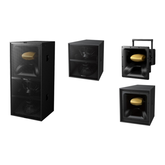
XY Series
XY-3B
XY-1
XY-2
XY-2E
pioneerproaudio.com
For support information such as a installation manual and recommended preset settings for these products, visit the website above.
Dual 12" three-way
Bi-amp loudspeaker
Dual 12" hybrid loaded
LF loudspeaker
8" two-way passive
mid-high loudspeaker
8" two-way Passive/Bi-Amp
mid-high loudspeaker
Version 1.0 Nov 2020
©2020 AlphaTheta Corporation
All rights reserved
Advertisement
Table of Contents

Related Manuals for Pioneer XY Series


Summary of Contents for Pioneer XY Series
- Page 1 Installation manual XY Series XY-3B Dual 12” three-way Bi-amp loudspeaker XY-1 Dual 12” hybrid loaded LF loudspeaker XY-2 8” two-way passive mid-high loudspeaker XY-2E 8” two-way Passive/Bi-Amp mid-high loudspeaker pioneerproaudio.com For support information such as a installation manual and recommended preset settings for these products, visit the website above.
-
Page 2: Table Of Contents
3.2.5 Suspension of enclosure using eye bolts P.30 3.2.6 Wheel Board P.32 4 System Configuration 4.1 Connections P.33 4.2 Changing the XY-2E operation mode 5 Specifications 5.1 Spec sheet P.38 5.2 Drawing P.40 Page 2 / 43 http://pioneerproaudio.com/ ©2018 Pioneer DJ CORPORATION... -
Page 3: Introduction
1 Introduction WARNING These loudspeakers must be installed by a qualified technician as it involves such tasks as selecting a location for installation, drilling holes in walls/ceiling and wiring. Have the installer carefully follow the installation instructions. Certain technical skills are required to install the loudspeaker. Please have the product installed by a professional. - Page 4 Do not attempt to use the product with the XY Series grille detached as doing so could result in damage to the product. Consult a qualified professional for assistance with removing the grille for maintenance purposes.
-
Page 5: Installation Guidelines
1 Introduction ____________________________________________________________________________________________________________ 1.2 Installation guidelines WARNING Ensure that the floor, wall, ceiling, or stage surface can withstand the weight of the system. Consult a qualified professional for advice if the strength of the surface is unknown. After installation, you must confirm that the speakers are safely installed. You must periodically check that the speakers are safely installed , without any loosen bolts, deterioration of parts, and so on. -
Page 6: Accessories
A safety steel can then be attached to this and connected to your safety point. Hardware standby The following hardware is provided with the XY series products so that commercially-available poles, brackets and other items can be attached. (see Table 2-1 "Hardware standby") - Page 7 2 Accessories __________________________________________________________________________________________________________ Table 2-1. Full-range loudspeaker Hardware XY-3B XY-1 XY-2 XY-2E Hardware 9 x M10 13 x M10 1 x M12 13 x M10 standby Mounting point threaded threaded mounting threaded points(*2) points (*2) point (*3) points (*2) 35 mm Speaker Pole polemount / Tripod Stand...
-
Page 8: Rigging And Caster Setting
3 Rigging And Caster Setting 3.1 Before Setting 3.1.1 Guide for safe use Improper installation of the speakers could cause them to fall and cause damage or injuries to persons nearby. Please check the following conditions of all the loudspeakers in this series always before they are rigged. - Page 9 THE SECONDARY SAFETY FEATURE - The secondary safety feature must be used to prevent the speaker from falling. Eye bolts to be used as secondary safety feature are not included with the products. When you use any commercially-available eyebolts, the above-listed safe working load limits and other specifications should be met. - With any suspension method, a second anchor point should be used as safety feature.
-
Page 10: Procedures
3 Rigging And Caster Setting __________________________________________________________________________________________________________ 3.2 Procedures 3.2.1 XY-2 Using the included yoke, suspension of the XY-2 from the ceiling, wall, and bottom of XY-3B/XY-1/XY-2E is available. The orientation of the enclosure can be changed at any angle. Several holes on both sides of the outer yoke of the cradle are used to change the length of the outer yoke so that the distance between the enclosure and the cradle can be adjusted. - Page 11 3 Rigging And Caster Setting __________________________________________________________________________________________________________ Procedure (XY-2 single use) 1 x φ13 Note: The yoke length can be changed by unscrewing the socket head bolts and choosing mounting holes in the both side plate ends of the yoke. The hole on the top of the yoke can be used to install the speaker to the ceiling or the wall in the horizontal position.
- Page 12 3 Rigging And Caster Setting __________________________________________________________________________________________________________ WARNING: - Excluding installation, do not loosen the XY-2 side hexagon socket head cap bolts. For secandary safety, ensure a commercially available eyebolt to the mounting point on the bottom of the speaker rear, securely fix the eye-bolt on the speaker and the hole on the back of XY-2 using secondary safety wire.
-
Page 13: Vertical Flying Cradle
3 Rigging And Caster Setting _________________________________________________________________________________________________________ 3.2.2 Vertical Flying Cradle To the ceiling When using the Vertical Flying Cradle, suspension of the XY-1 and XY-2E enclosure vertically from the ceiling as shown in the right figure is available. Speaker models compatible with respective Vertical Flying Cradles are shown in the table below. - Page 14 3 Rigging And Caster Setting _________________________________________________________________________________________________________ Procedure (CP-XY1VC1) Remove the eight pre-inserted mounting screws from the rateral of enclosure. (Fig.3-2-2-A) NOTE: XY-1 is shown in the illustrations below. Fig.3-2-2-A (2) Using the supplied six M10 socket head bolts (C), align the (D) (E) mounting holes in the side plate (A)/(B) with the mounting points on the rateral of the enclosure.
- Page 15 3 Rigging And Caster Setting _________________________________________________________________________________________________________ When the yoke is attached to the speaker first Using the supplied four M10 socket head bolts (G), align the (3a) main mounting holes and the hole for angle adjustment in the yoke (F) with the mounting points on the side plate. Ensure that both the Flat Washer (H) and the Spring Washer (I) are used - the Flat Washer (H) should be in contact with the cradle.
- Page 16 3 Rigging And Caster Setting _________________________________________________________________________________________________________ Attach the two socket head bolt (G) to the temporary fixing (4b) points on the side plate. Insert the bolts into the side plate by about 10 mm. There is no need to install the Flat washer and Spring washer with the bolts.
- Page 17 3 Rigging And Caster Setting _________________________________________________________________________________________________________ Loosen the bolts for securing the bolts for adjusting the angle, (7b) and adjust the direction of the speaker. Once the direction of the speaker is determined, tighten the bolts firmly to secure the speaker to the yoke.
-
Page 18: Variable Angle Bracket
3 Rigging And Caster Setting __________________________________________________________________________________________________________ 3.2.3 Variable Angle Bracket NOTE: XY-3B is shown in the illustration. When using the Variable Angle Bracket, suspension of the enclosure vertically from the ceiling as shown in the right figure is available. It is easier to change the inclined angle of Variable Angle Bracket than that of To the ceiling Vertical Flying Cradle. - Page 19 3 Rigging And Caster Setting __________________________________________________________________________________________________________ Part list (CP-XY3DF1) Service Required tools Item Part Name Note Part No. - 8mm hex key Dual Enclosure Flying Plate Rear Plate Top 10B917L Disuse Rear Plate Bottom 10B917S Disuse M10 x 20mm (P=1.5), M10 socket head bolt 06B522 8mm hex socket head...
- Page 20 3 Rigging And Caster Setting __________________________________________________________________________________________________________ The holes on the top plate can be used to install the speaker to the ceiling. (Fig.3-2-3-C) Note: To the ceiling - For larger down-tilt angles, position the pivot on the last hole and use the mounting point on the rear or underside as a pull-back.
- Page 21 3 Rigging And Caster Setting __________________________________________________________________________________________________________ (3) Ensure the commercially-available eyebolt are secured to mounting point on the rear top of the enclosure to suspend it with wire as a Commercially secondary safety feature. (Fig.3-2-3-E) -available For preventing to occur the noise from secondary safety wires, eyebolt wire length should be as short as possible.
-
Page 22: Dual Enclosure Flying Plate Set
3 Rigging And Caster Setting __________________________________________________________________________________________________________ 3.2.4 Dual Enclosure Flying Plate Set When using the Dual Enclosure Flying Plate Set, multiple enclosures can be stably combined side by side and suspended from the ceiling as shown in the figure below. Table.3-2-4-A: Models compatible with Dual Enclosure Flying Plate Set and inclined angle between the 2 enclosures NOTE: XY-3Bs are shown in the illustration. - Page 23 3 Rigging And Caster Setting __________________________________________________________________________________________________________ Part list (CP-XY3DF1) Service Item Part Name Note Part No. Vertical connection plate M10 x 35 mm (P=1.5), M10 countersunk bolt 6 mm hex socket head, Included spare:1 Rubber pad Part list (CP-XY1DF1) Service Required tools Item Part Name Note...
- Page 24 3 Rigging And Caster Setting __________________________________________________________________________________________________________ Refer to the instructions below to install a rear plate on the back of each speaker. CP-XY1DF1 Using the supplied M10 socket head bolts(B), align the mounting holes on the Rear plate bottom(F) with the mounting points of the rear of the enclosures.
- Page 25 3 Rigging And Caster Setting __________________________________________________________________________________________________________ Note: - For larger down-tilt angles, position the pivot on the last hole and use the point on the rear or underside as a pull-back. Commercially - XY-2 can be attached to the bottom of each enclosure. -available wire WARNING: - Attach two or more wire to a rigging point different from those for...
- Page 26 3 Rigging And Caster Setting __________________________________________________________________________________________________________ Assembling the cluster using Dual enclosure flying plate and Vertical connection plate By using the dual enclosure flying plate and vertical connection plate, XY-1/XY-2E can be connected horizontally and vertically to assemble a cluster. NOTE: All the parts for a combination of Dual Enclosure Flying Plate Set and Vertical connection plate set should be compatible with respective speakers, XY-1 and XY-2E.
- Page 27 3 Rigging And Caster Setting __________________________________________________________________________________________________________ Part list Dual Enclosure Flying Plate Set (CP-XY1DF1) Service Item Part Name Note Part No. Dual Enclosure Flying Plate Rear Plate M10 x 20mm (P=1.5), M10 socket head bolt 8mm hex socket head, Included spare:1 Spring washer M10, Included spare:1 Flat washer...
- Page 28 3 Rigging And Caster Setting __________________________________________________________________________________________________________ Remove the blindfold screws on the sides of XY-1/XY-2E, and use Countersunk bolts to secure the vertical connection plate to the speaker and connect the upper and lower speakers together. Tighten the bolts at 15N·m torque. (Fig.3-2-4-I) Fig.3-2-4-I Secure each stack connected by CP-XY1CON1 with the top plate of CP-XY1DF1.
- Page 29 3 Rigging And Caster Setting __________________________________________________________________________________________________________ To the ceiling Holes on the top plate can be used to install the speaker to the ceiling. (Fig.3-2-4-L) Note: Only CP-XY1VC1 When using the CP-XY1DF1 to connect different left and right speakers, a wire can be attached to the balancing point and pulled to keep the weight balanced.
- Page 30 3 Rigging And Caster Setting ___________________________________________________________________________________________________________ 3.2.5 Suspension of the enclosure using the eyebolt The speaker has the mounting points where commercially-available eyebolts can be mounted. Using the commercially-available eyebolts, a speaker or a combination of them can be vertically suspended. WARNING: Specification of eyebolt If you use any commercially available eyebolt, ensure it is the same size as in the list below and...
- Page 31 3 Rigging And Caster Setting ___________________________________________________________________________________________________________ The enclosure can be inclined downward. The locations and number of mounting points of each model are listed in the Table.3-2-5-C. Table.3-2-5-C: Locations and number of mounting points of each model XY-3B Bottom Rear *Center hole is only for combining XY-2 XY-1 / XY-2E...
-
Page 32: Wheel Board
3 Rigging And Caster Setting ___________________________________________________________________________________________________________ 3.2.6 Wheel Board A wheel board to help with transportation can be attached to the front of the XY-3B. Lock casters are provided to prevent unexpected movement with the wheel board. Also, you can use the wheel boards to stack two enclosures. -
Page 33: System Configuration
4 System Configuration 4.1 Connections Power Amplifier Recommendations In order to deliver best audio quality, amplifiers made by Powersoft is recommended to be used with the XY series loudspeakers. Please refer to the table below for the combination of amplifiers with respective loudspeakers. Table 4-1-1 Specification of Loudspeaker XY-3B Speaker model... - Page 34 Speaker used. Using wrong pinouts may cause damage to the speakers or cause accidents. The XY Series are supplied as standard with Neutrik SpeakON™ NL4 connectors, wired pin 1+/1– and 2+/2-. Pin 2+/2- is used for mid-high drivers in the XY-3B, and in the other models used for only link-through.
- Page 35 4 System Configuration ____________________________________________________________________________________________________________ CAUTION : Each amplifier has different pinouts for the Neutrik SpeakON™ connectors(NL4) . Following are only examples of connection. Please refer to the amplifier's manual for further information. X-Series Two single-ended loads Bridge-tied load OUT1 OUT2 invertin invertin K-Series...
-
Page 36: Changing The Xy-2E Operation Mode
4 System Configuration ____________________________________________________________________________________________________________ 4.2 Changing the XY-2E operation mode The operation mode of the XY-2E can be changed from the Passive mode (Initial state) to the Bi-amp mode. When changing the operation mode. WARNING: If wiring is carried out incorrectly, it may result in damage to the amplifier and speaker unit. Procedure Remove the Phillips screw from the door at the Disconnect the cable connected to the back of... - Page 37 4 System Configuration ____________________________________________________________________________________________________________ 2- : Yellow 2+ : White Attach the door to the enclosure. The speaker cable connection and the drive unit driven by the speaker cable correspond to the following. 1+/1- : MF unit 2+/2- : HF unit Page 37 / 43 http://pioneerproaudio.com/ ©2020 AlphaTheta CORPORATION...
-
Page 38: Specifications
5 Specifications 5.1 Spec sheet Product Name XY-3B/XY-3B-W XY-1/XY-1-W XY-2 Dual 12” hybrid loaded 8” two-way Passive Dual 12” three-way bi-amp loudspeaker Loudspeaker Type LF loudspeaker mid-high loudspeaker Section Frequency Response 55 Hz to 400 Hz (-10 dB @ 45 Hz) 235 Hz to 17 kHz (-10 dB @ 150 Hz) 55 Hz to 400 Hz (-10 dB @ 45 Hz) 235 Hz to 17 kHz (-10 dB @ 150 Hz) - Page 39 5 Specifications 5.1 Spec sheet Product Name XY-2E/XY-2E-W (Passive mode) XY-2E/XY-2E-W (Bi-amp mode) 8” two-way Passive/Bi-Amp mid-high loudspeaker Loudspeaker Type Section Frequency Response 235 Hz to 17 kHz (-10 dB @ 150 Hz) MF: 235 Hz to 3.5 kHz (-10 dB @ 150 Hz) HF: 1.4 kHz to 17 kHz (+/ -3dB)* 1.
-
Page 40: Drawing
5 Specifications 5.2 Drawing NOTE: The nuts of the threaded fixing points on XY-3B are structured so that bolts cannot pass through them. (max threaded length is 15mm.) Copyright @ 2020 AlphaTheta Corporation... - Page 41 5 Specifications 5.2 Drawing Copyright @ 2020 AlphaTheta Corporation XY-1 1:12...
- Page 42 5 Specifications 5.2 Drawing Copyright @ 2020 AlphaTheta Corporation...
- Page 43 5 Specifications 5.2 Drawing Copyright @ 2020 AlphaTheta Corporation XY-2E 1:12...