
Related Manuals for ABB Welcome IP H8236 Series


Summary of Contents for ABB Welcome IP H8236 Series
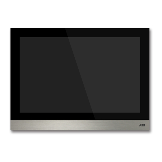
- Page 1 2TMD041800D0002 │ 31.03.2021 Product manual ABB-Welcome IP H8236-._H8237-. IP touch...
-
Page 2: Table Of Contents
Tab le of c ont e nts Notes on the instruction manual ......................6 Safety ..............................6 Intended use ............................7 Environment ............................9 ABB devices ..........................9 Product description ..........................10 Device type ..........................10 Control elements........................12 Terminal description ......................... 13 Technical data ............................ - Page 3 Table of contents 8.4.17 Resetting user settings ......................84 8.4.18 Resetting engineering password.................... 85 8.4.19 Viewing the version....................... 86 8.4.20 Viewing the device address ....................87 8.4.21 Obtaining the product manual....................88 8.4.22 Updating the firmware ......................90 Engineering settings ........................ 92 8.5.1 Enter engineering setting ......................
- Page 4 Table of contents 8.9.13 Lift control setting ........................180 8.9.14 Anti-flicker setting ........................181 8.9.15 Call forward setting ......................182 8.9.16 Wiegand setting........................183 8.9.17 Pushbutton setting .......................184 8.9.18 Time sync setting.........................186 8.9.19 Compatible mode setting .....................187 8.9.20 Updating the firmware ......................188 8.9.21 Viewing the version......................190 8.9.22 Viewing the serial number ....................191 8.10 IP actuator settings ........................
- Page 5 Table of contents Voice message ........................242 9.7.1 Creating a voice message ....................242 9.7.2 Reading a voice message ....................243 9.7.3 Removing voice messages ....................244 Text message ........................246 9.8.1 Accessing the "Text message" screen ..................246 9.8.2 Sending a text message.......................247 9.8.3 Replying a text message ......................249 9.8.4...
-
Page 6: Notes On The Instruction Manual
Please keep this manual in a safe place. If you pass the device on, also pass on this manual along with it. ABB accepts no liability for any failure to observe the instructions in this manual. Safety... -
Page 7: Intended Use
Intended use Intended use This device is a central control panel of the ABB-Welcome IP system and operates exclusively with components from this system. The device must only be installed in dry indoor rooms. WiFi installation Note If the device supports WiFi function, please make sure the device has good WiFi signal reception before installation. - Page 8 Do not remove SD card or reboot indoor station while recording or copying images onto the SD card, otherwise this SD card may fail to preform when recording or playing images. ABB is no responsible for the performance of an SDHC card. ■ IP-Cam Note The indoor station supports IP-Cam with onvif protocol (Profile S).
-
Page 9: Environment
ABB devices All packaging materials and devices from ABB bear the markings and test seals for proper disposal. Always dispose of the packing materials and electric devices and their components via an authorized collection facility or disposal company. -
Page 10: Product Description
Product description Product description Device type Article Order number Product name Color Size (mm) number H8236-1BG 2TMA130050B0061 IP touch 7",DES,LAN Black 198.5 x 149.6 x 36 H8236-1WG 2TMA130050W0061 IP touch 7",DES,LAN White 198.5 x 149.6 x 36 IP touch 7",DES+KNX+f@h+APP,L H8236-4B 2TMA130050B0065 AN+WiFi,T-loop... - Page 11 Product description Article Order number Product name Color Size (mm) number IP touch 10",DES+KNX+f@h+APP, H8237-4B 2TMA130050B0054 LAN+WiFi,T-loop Black 251 x 185 x 27 IP touch 10",DES+KNX+f@h+APP, LAN+WiFi,T-loop H8237-4W 2TMA130050W0054 White 251 x 185 x 27 IP touch 10",DES+KNX+f@h+APP, LAN+LAN,T-loop H8237-5B 2TMA130050B0055 Black 251 x 185 x 31...
-
Page 12: Control Elements
Product description Control elements IP touch 7 Function Touch screen IP touch 10 Function Touch screen │12 Product manual 2TMD041800D0002... -
Page 13: Terminal Description
Product description Terminal description IP touch 7 Function Power input connector Power input connector (DC-JACK input) Doorbell connector LAN1 (PoE) Micro USB Upgrade connector Extension module connector Microphone Dismantling switch Micro SD card connector Speaker LAN2 Alarm connector RS485 connector, 12 V output, emergency port (SOS, GAS, fire) Relay output IP touch 7 (LAN+LAN) IP touch 7 (LAN) - Page 14 Product description IP touch 10 Function Power input connector Power input connector (DC-JACK input) Doorbell connector LAN1 (PoE) Micro USB Upgrade connector Interface module connector Microphone Dismantling switch Micro SD card connector Speaker LAN2 Alarm connector RS485 connector, 12 V output (12 V output is not available when PoE powered) Relay output IP touch 10 (LAN+LAN) │14...
-
Page 15: Technical Data
Technical data Technical data IP touch 7 Designation Value ⎓ Rating voltage 24 V ⎓ Operating voltage range 20-27 V ⎓ 27 V , 250 mA Rating current ⎓ 24 V , 280 mA ⎓ 27 V , 390 mA Rating current ⎓... - Page 16 Technical data IP touch 10 Designation Value ⎓ Rating voltage 24 V ⎓ Operating voltage range 20-27 V ⎓ 27 V , 390 mA Rating current ⎓ 24 V , 440 mA ⎓ 27 V , 520 mA Rating current ⎓...
-
Page 17: Mounting/Installation
Mounting/Installation Mounting/Installation Warning Electric voltage! Dangerous currents flow through the body when coming into direct or indirect contact with live components. This can result in electric shock, burns or even death. – Disconnect the mains power supply prior to installation and/or disassembly! –... -
Page 18: Product Dimensions
Mounting/Installation Product dimensions Uint: mm 250.8 198.5 149.8 IP touch 7 IP touch 10 Installation height 1.50 m (4.9 feet) │18 Product manual 2TMD041800D0002... -
Page 19: Surface-Mounted Installation
Mounting/Installation Surface-mounted installation This installation method is not suitable for IP touch (LAN+LAN). Surface-mounted box – IP touch 7 Uint: mm 170.8 131.4 120.7 120.7 Global VDE&BS&CN NEMA 83.3 83.3 79.2 NEMA NEMA&Italy Swiss IP touch 10 Uint: mm 120.7 120.7 Global VDE&BS&CN... - Page 20 Mounting/Installation Installation │20 Product manual 2TMD041800D0002...
-
Page 21: Flush-Mounted Installation
Mounting/Installation Flush-mounted installation With pre-installation box 192 mm 144 mm 54 mm │21 Product manual 2TMD041800D0002... -
Page 22: Cavity Wall Installation
Mounting/Installation Cavity wall installation │22 Product manual 2TMD041800D0002... -
Page 23: Desktop Installation
Mounting/Installation Desktop installation This installation method is not suitable for IP touch (LAN+LAN). │23 Product manual 2TMD041800D0002... -
Page 24: Dismantling
Mounting/Installation Dismantling Replacing the end strip This operation is not suitable for full glass IP touch. │24 Product manual 2TMD041800D0002... -
Page 25: Commissioning
Commissioning Commissioning Initial setup This indoor station enters initial setup automatically when powered on the first time or "Clear all data" is carried out on the "Engineering settings" screen. Please see the "Clear all data" chapter for more details. 1. Selecting a system language │25 Product manual 2TMD041800D0002... - Page 26 Commissioning 2. Acceptping the licensing terms │26 Product manual 2TMD041800D0002...
- Page 27 Commissioning 3. Selecting a country 4. Setting the date and time │27 Product manual 2TMD041800D0002...
- Page 28 Commissioning 5. Setting the WiFi This setting applies to IP touch (LAN+WiFi) only. Please see the "Network settings" chapter for more details. │28 Product manual 2TMD041800D0002...
-
Page 29: Home Screen
Commissioning Home screen The home screen displays a "★" at the bottom. The system default home screen is "Home automation" screen. The Home screen can be set on the "Engineering setting" screen. . │29 Product manual 2TMD041800D0002... -
Page 30: Extra Screen
Commissioning Extra screen The extra screen displays "-" at the bottom of the screen. │30 Product manual 2TMD041800D0002... -
Page 31: System Settings
Commissioning System settings 8.4.1 Accessing the "System settings" screen On the extra screen, click "System" to access the corresponding screen. │31 Product manual 2TMD041800D0002... -
Page 32: Sound Setting
Commissioning 8.4.2 Sound setting On the "System settings" screen, click "Sound" to access the corresponding screen. Function Touch tone setting Ringtone setting Click the drop-down list to select the ringtones for outdoor station, indoor stations, guard unit and doorbell (built-in 4 ringtones). Customized ringtone A maximum of 3 customized ringtones can be added from an SD card. -
Page 33: Language Setting
Commissioning 8.4.3 Language setting On the "System settings" screen, click "Language" to access the corresponding screen. │33 Product manual 2TMD041800D0002... -
Page 34: Network Setting
Commissioning 8.4.4 Network setting WIFI settings This setting applies to IP touch (LAN+WiFi) only. 1. Connect WiFi Please ensure the "SSID broadcast" function is used on the router. On the "System settings" screen, click "Network settings" >> "WiFi settings". The indoor station will obtain an SSID list automatically. Select a WiFi name from the SSID list and enter the password to connect to that WiFi network. - Page 35 Commissioning 2. Disconnect WiFi Select the designated WiFi name from the SSID list, click "Ignore" or "Disconnect" to disconnect the WiFi. Ignore: password needed to reconnect this WiFi. Disconnect: no password needed to reconnect this WiFi. Go to the "Network settings" screen, the WiFi name will disappear if successful. │35 Product manual 2TMD041800D0002...
- Page 36 Commissioning IP address setting The indoor station uses DHCP to obtain an IP address from the router by default. It is also possible to set the IP address by unticking the checkbox (example below). │36 Product manual 2TMD041800D0002...
-
Page 37: Automatic Snapshot Setting
Commissioning 8.4.5 Automatic snapshot setting On the "System settings" screen, click "Door Entry System" to access the corresponding screen. Then tick the "Automatic snapshots" checkbox to enable the function. The indoor station will take 3 snapshots automatically during an incoming call. │37 Product manual 2TMD041800D0002... -
Page 38: Absence Message Setting
Commissioning 8.4.6 Absence message setting The indoor station allows you to leave voice messages for visitors and to record voice message from visitors. Enable "Absence message" Note At least one voice message must exist before this function can be used. . Please follow the steps: [1] On the IP touch screen, tap "... - Page 39 Commissioning [2] Tap "Voice message". [3] Tap " " to enter the setting mode. If "√ Absence message" has been displayed on the screen, please continue step 6 and step 7, otherwise continue step 4 and step 5. │39 Product manual 2TMD041800D0002...
- Page 40 Commissioning [4] Tick the check box "Absence message". [5] Tap "OK" to save the setting. │40 Product manual 2TMD041800D0002...
- Page 41 Commissioning [6] On the "System settings" screen, tap "Door Entry System". [7] Tick the check box "Absence message" to enable the function. │41 Product manual 2TMD041800D0002...
- Page 42 Commissioning Disable "Absence message" Please follow the steps: [1] On the "System settings" screen, tap "Door Entry System". [2] Untick the check box "Absence message" to disable the function. │42 Product manual 2TMD041800D0002...
-
Page 43: Unlock Button Setting
Commissioning 8.4.7 Unlock button setting Unlock button In standby status, on the "Door Entry" screen, unlock button is disabled by default. │43 Product manual 2TMD041800D0002... - Page 44 Commissioning Activating the "Releasing the default lock" function Please follow the steps to activate the function: [1] On the "System settings" screen, tap "Door Entry System". [2] Tap "Address of default unlock". [3] Select the lock type from the drop-down list. It can be set to "Door lock" or "Actuator lock". [4] Select the designated device from the drop-down list.
- Page 45 Commissioning Note If gate station (device type = GS) or network IP actuator need to be assigned the function, a gate station (device ID =1) must be used before assignment. If building outdoor station (device type = OS) or building IP actuator need to be assigned the function, a building outdoor station (device ID =1) must be used before assignment.
-
Page 46: Program Button Setting
Commissioning 8.4.8 Program button setting Program button In standby status, on the "Door Entry" screen, program button is disabled by default. │46 Product manual 2TMD041800D0002... - Page 47 Commissioning Assigning the "Open auxiliary lock" function Please follow the steps to assign the address: [1] On the "System settings" screen, tap "Door Entry System". Program button is assigned to the "Open auxiliary lock" function by default. [2] Tap "Address of default unlock". [3] Select the lock type from the drop-down list.
- Page 48 Commissioning Note If gate station (device type = GS) or network IP actuator need to be assigned the function, a gate station (device ID =1) must be used before assignment. If building outdoor station (device type = OS) or building IP actuator need to be assigned the function, a building outdoor station (device ID =1) must be used before assignment.
- Page 49 Commissioning Assigning the "Turn on the light" function Please follow the steps to assign the address: [1] On the "System settings" screen, tap "Door Entry System". [2] Select "Turn on the light" from the drop-down list. [3] Select the IP actuator type from the drop-down list. It can be set to "Network IP actuator", "Building IP actuator"...
- Page 50 Commissioning [5] In standby status, on the "Door Entry" screen, the program button has been assigned to "Turn on the light" function. │50 Product manual 2TMD041800D0002...
- Page 51 Commissioning Disable the program button Please follow the steps to assign the address: [1] On the "System settings" screen, tap "Door Entry System". [2] Select "Invalid" from the drop-down list. [3] In standby status, on the "Door Entry" screen, the program button has been disabled the function.
-
Page 52: Auto Unlock Setting
Commissioning 8.4.9 Auto unlock setting You can use the "Auto unlock" function to release the locks on the default outdoor station automatically during the designated period. Precondition On the "Engineer settings", "Local settings" screen, the "Unlock timer" function must be enabled. │52 Product manual 2TMD041800D0002... - Page 53 Commissioning Auto unlock setting Please follow the steps below: [1] On the extra screen, tap "Unlock timer" to access the corresponding screen. [2] Tap " ". │53 Product manual 2TMD041800D0002...
- Page 54 Commissioning [3] Tap "Add automatic unlock". [4] Select the days of the week, with the selected options shown with highlighting. [5] Set the start time. [6] Set the end time. [7] Tap "OK". │54 Product manual 2TMD041800D0002...
- Page 55 Commissioning Note A maximum of 10 items is supported. [8] With this setting, this device will enter auto unlock mode automatically and display " " on the status bar. [9] The lock will be released automatically 5 s later during an incoming call. │55 Product manual 2TMD041800D0002...
-
Page 56: Card Management
Commissioning 8.4.10 Card management This indoor station can manage IC cards for IP pushbutton outdoor station. Note It is recommended that IC cards are created and maintained using local outdoor stations or management software only. On the "System settings" screen, click "Door Entry System", "Card management", and enter the user password (the system default is 123456) to access the corresponding screen. - Page 57 Commissioning Card register 1. Enter registering mode On the "Card management" screen, click "Card register", select the device and then click "Card register". The pushbutton module on the outdoor station will flash orange as a prompt to swipe an IC card. 2.
- Page 58 Commissioning Card delete 1. Entering delete mode On the "Card management" screen, click "Card delete", select the device and then click "Card delete". The pushbutton module on the outdoor station will flash orange as a prompt to swipe an IC card. 2.
- Page 59 Commissioning Card clear On the "Card management" screen, click "Card clear", select the device and click "Card clear". Card sync On the "Card management" screen, click "Card sync", select a source device and a target device, then click "Card sync". │59 Product manual 2TMD041800D0002...
-
Page 60: Display Setting
Commissioning 8.4.11 Display setting On the "System settings" screen, click "Display" to access the corresponding screen. Function Clean screen Please see the "Clean screen" chapter for more details. Brightness Screensaver ■ "Digital clock": displays the current time at a random position on the screen. ■... -
Page 61: Date And Time Setting
Commissioning 8.4.12 Date and time setting On the "System settings" screen, click "Date and time" to access the corresponding screen. Function Sync time type Tick the checkbox to sync date and time from the management software or from NTP automatically. Time and date setting Set time zone If you don’t sync date and time from management software or from NTP. -
Page 62: Home Monitor Settings
Commissioning 8.4.13 Home monitor settings You can use this IP touch to monitor the private IP cameras. This IP touch and the camera must be on the same network. Note Video streaming between the indoor station and the 3rd party camera is unencrypted. - Page 63 Commissioning [3] Tap " ". [4] Tap " " to search the IP cameras automatically. │63 Product manual 2TMD041800D0002...
- Page 64 Commissioning [5] The designated camera is displayed on the screen. [6] Tap " ". [7] Enter the alias name. [8] Enter the user account and password. [9] Tap "OK". │64 Product manual 2TMD041800D0002...
- Page 65 Commissioning [10] " " will be displayed if successful. [11] Tap " ". [12] Tick the check box to enable the function. │65 Product manual 2TMD041800D0002...
- Page 66 Commissioning [13] On the "Engineer settings" screen, tap "Local settings". [14] Switch on the "CCTV" function. [15] On the extra screen, tap "CCTV". │66 Product manual 2TMD041800D0002...
- Page 67 Commissioning [16] The image of the designated camera is displayed on the screen. Select the other camera from the drop-down list. [17] Tap to switch to the previous one or the next one. │67 Product manual 2TMD041800D0002...
-
Page 68: Community Monitor Settings
Commissioning 8.4.14 Community monitor settings On the "System settings" screen, click "Monitor settings", "Community monitor" to access the corresponding screen. Click to download the camera list from the management software. │68 Product manual 2TMD041800D0002... -
Page 69: App Settings
8.4.15 App settings 1. Registering an account on the MyBuildings portal https://mybuildings.abb.com Access the link: , and click "Register". Fill in the form as required to register an account. Then activate the user account when you receive the email sent from the MyBuilding portal. - Page 70 Commissioning 2. Logging into the MyBuildings portal on the indoor station │70 Product manual 2TMD041800D0002...
- Page 71 Commissioning 3. Downloading and installing the APP Download the APP from Google Play or the APP Store via the keyword "ABB Welcome". Then install the relevant APP on mobile or tablet. Note The following snapshots used in this document were taken on the IOS system.
- Page 72 Commissioning If you do not grant the permissions, you will be able to add them later on. For example, click " " to access the settings screen on the mobile, swipe the screen down and then click to accept the permissions. │72 Product manual 2TMD041800D0002...
- Page 73 Commissioning 4. Logging into the app On the mobile phone/tablet, click to open the app, enter the user name, password and alias, tick the checkboxes to accept all the terms and conditions, then click "Log in". Note If an incorrect password is entered more than 3 times, no further attempts are permitted within certain period of time.
- Page 74 Commissioning 5. Pairing the devices On the APP "Home" screen, tap "∨", followed by "Pair devices", "IP gateway". Then tap to call up the device list, and select the alias, click "OK" to send a pairing request to the indoor station. Please write down the token ID (e.g. 1849C4BC in this case). │74 Product manual 2TMD041800D0002...
- Page 75 Commissioning On the "System settings", "APP settings" screen of the indoor station, click "Unpaired", select the relevant functions in the pop-up window, and click "Pair". │75 Product manual 2TMD041800D0002...
- Page 76 Commissioning Enter the token ID and click "OK". The indoor station will display "Paired" if successful. │76 Product manual 2TMD041800D0002...
- Page 77 Commissioning 6. Portal Sync If you have purchased a remote service, you can click "Portal sync" on the "APP settings" screen to enable the remote service immediately. │77 Product manual 2TMD041800D0002...
-
Page 78: Changing Password
Commissioning 8.4.16 Changing password User password The system default user password is 123456. It can be used to set the following functions: ■ Card management ■ Reset user setting App setting ■ ■ Basic zone setting Set alarm timer ■ ■... - Page 79 Commissioning [3] Input original password. [4] Input new password twice. [5] Click "OK" to save the setting. Password rule This password must not include continuously increasing or decreasing numbers (e.g. 123456, 654321). Three consecutive identical numbers are similarly not permitted (e.g. 123444, 666888). │79 Product manual 2TMD041800D0002...
- Page 80 Commissioning Unlock password This password is used to release the lock of the outdoor station by entering the password. Changing unlock password Please follow the steps below: [1] On the "System settings" screen, tap "Change password". [2] Tap "Change unlock password". │80 Product manual 2TMD041800D0002...
- Page 81 Commissioning [3] Input new password twice (3…8 digits). [4] Click "OK" to save the setting. Password rule This password must not include continuously increasing or decreasing numbers (e.g. 123456, 654321). Three consecutive identical numbers are similarly not permitted (e.g. 123444, 666888). │81 Product manual 2TMD041800D0002...
- Page 82 Commissioning Duress password When the resident is under duress, he can enter this password to disarm the indoor station. At the same time, an alarm message is sent to the guard unit and the management software. The system default user password is 654321. Changing duress password Please follow the steps below: [1] On the "System settings"...
- Page 83 Commissioning [3] Input original password. [4] Input new password twice. [5] Click "OK" to save the setting. Password rule This password must not include continuously increasing or decreasing numbers (e.g. 123456, 654321). Three consecutive identical numbers are similarly not permitted (e.g. 123444, 666888). │83 Product manual 2TMD041800D0002...
-
Page 84: Resetting User Settings
Commissioning 8.4.17 Resetting user settings Please follow the steps below: [1] On the "System settings" screen, tap "Reset settings". [2] Tap "Reset user settings" [3] Enter the user password (the system default is 123456). [4] Tap "OK". │84 Product manual 2TMD041800D0002... -
Page 85: Resetting Engineering Password
Commissioning 8.4.18 Resetting engineering password Note This function is only available for 120 s when this indoor station is powered on. This function reset the engineering password to the default value (345678). Please follow the steps below: [1] On the "System settings" screen, tap "Reset settings". [2] Tap "Reset engineering pwd."... -
Page 86: Viewing The Version
Commissioning 8.4.19 Viewing the version On the "System settings" screen, click "About" to view the version information. │86 Product manual 2TMD041800D0002... -
Page 87: Viewing The Device Address
Commissioning 8.4.20 Viewing the device address On the "System settings" screen, click "About" to view the address information. │87 Product manual 2TMD041800D0002... -
Page 88: Obtaining The Product Manual
Commissioning 8.4.21 Obtaining the product manual Please follow the steps below: [1] On the "System settings" screen, tap "About". [2] Using the mobile to scan the QR code to access the website. │88 Product manual 2TMD041800D0002... - Page 89 Commissioning [3] On the website, click "Downloads". [4] Click "Manual". [5] Click "PDF" to download the file. │89 Product manual 2TMD041800D0002...
-
Page 90: Updating The Firmware
Commissioning 8.4.22 Updating the firmware Please follow the steps below: [1] On the "System settings" screen, tap "About". [2] Using the mobile to scan the QR code to access the website. [3] On the website, click "Downloads". [4] Click "Software". [5] Click "ZIP"... - Page 91 Commissioning [6] Unzip the zip file (1 .img file and 1 .sig file), copy these 2 files to an SD card. [7] Insert the SD card to the IP touch. An icon will be displayed on the status bar if the SD card is inserted successfully.
-
Page 92: Engineering Settings
Commissioning Engineering settings 8.5.1 Enter engineering setting Engineering password The system default engineering password is 345678. The user must change the engineering password when accessing the engineering settings for the first time. Please follow the steps below: [1] On the "System settings" screen, tap "Engineering settings". [2] Input original password. - Page 93 Commissioning Enter engineering setting Please follow the steps below: [1] On the "System settings" screen, tap "Engineering settings". [2] Input engineering password. [3] Click "OK" to access the "Engineering settings" screen. Wrong password If the wrong password is entered 10 times within 5 minutes, it is not possible to enter the password again for 5 minutes.
-
Page 94: Accessing The "Local Settings" Screen
Commissioning 8.5.2 Accessing the "Local settings" screen On the "Engineering settings" screen, tap "Local settings" to access the corresponding screen. │94 Product manual 2TMD041800D0002... -
Page 95: Call Mode Setting
Commissioning 8.5.3 Call mode setting 1. Call mode = physical address (default) In this mode, when the user wants to initiate an intercom call, he needs to enter the physical address (e.g. "001-0102"). 2. Call mode = logical address In this mode, when the user wants to initiate an intercom call, he needs to enter the logical address (e.g. - Page 96 Commissioning │96 Product manual 2TMD041800D0002...
- Page 97 Commissioning Please follow the steps below: [1] On the "Local settings" screen, select call mode from the drop-down list. [2] Tap " " to exit the setting, tap "OK" to save the settings. For more information, . │97 Product manual 2TMD041800D0002...
-
Page 98: Device Mode Setting
Commissioning 8.5.4 Device mode setting 1. Master mode Only one indoor station can be set to master mode in the same apartment. Both IP touch (LAN+LAN) and IP touch (LAN+WiFi) can be set to master mode. Community Home LA N1 IP touch (Subsidiary mode) (LAN) - Page 99 Commissioning 2. Subsidiary mode In the same apartment, except master indoor station, other indoor stations must be set to subsidiary indoor station. All types of indoor stations can be set to subsidiary indoor station. Community Home LA N1 IP touch (Subsidiary mode) (LAN) Switch...
- Page 100 Commissioning 3. Independent mode If IP touch is set to independent mode, no other devices can be supported. The independent indoor station can be managed by using management software. Community Home Switch LAN1 IP touch (LAN) (Independent mode) Please follow the steps below: [1] On the "Local settings"...
-
Page 101: Home Network Port Setting
Commissioning 8.5.5 Home network port setting Home network port means the port connect to the router via LAN or WiFi. Community Home LA N1 IP touch (Subsidiary mode) (LAN) Switch (Optional) IP touch (Subsidiary mode) LAN2 (LAN+LAN) (Optional) IP touch (Subsidiary mode) (LAN+WiFi) (Optional) -
Page 102: Default Home
Commissioning 8.5.6 Default home page setting Default home page can be selected among "H/A" (default), "DES" and "CCTV". Follow the steps below to change the setting: [1] On the "Local settings" screen, select default home page from the drop-down list. [2] Tap "... -
Page 103: Function Management
Commissioning 8.5.7 Function management Please follow the steps: [1] On the "Local settings" screen, tap the designated slider to switch on/off the function. [2] Tap " " to exit the setting, tap "OK" to save the settings. │103 Product manual 2TMD041800D0002... -
Page 104: Screensaver Picture Setting
Commissioning 8.5.8 Screensaver picture setting Please follow the steps: [1] On the "Local settings" screen, tap " ". [2] Select the designated picture from the SD card. [3] Tap " " to exit the setting, tap "OK" to save the settings. Note The picture supports .jpg, .png and .bmp format, with a maximum resolution of 2048 x 1920. -
Page 105: Default Guard Unit Setting
Commissioning 8.5.9 Default guard unit setting Please follow the steps: [1] On the "Local settings" screen, tap "Address of default guard unit". [2] Enter the address (1…32). [3] Tap " " to exit the setting, tap "OK" to save the settings. │105 Product manual 2TMD041800D0002... -
Page 106: Exporting The Configuration File
Commissioning 8.5.10 Exporting the configuration file Note An SD card must be inserted to the IP touch before use. Please follow the steps: [1] On the "Local settings" screen, tap "Import/export configuration". [2] Select the designated functions. [3] Tap "Export configuration file" to output a configuration file to the SD card. │106 Product manual 2TMD041800D0002... -
Page 107: Importing The Configuration File
Commissioning 8.5.11 Importing the configuration file Note An SD card must be inserted to the IP touch before use. Please follow the steps: [1] On the "Local settings" screen, tap "Import/export configuration". [2] Tap "Import configuration file" to import a configuration file from the SD card. │107 Product manual 2TMD041800D0002... -
Page 108: Compatible Mode Setting
Commissioning 8.5.12 Compatible mode setting The IP touch works in security mode to guarantee the high security ("Compatible mode is disabled by default). It’s suggested compatible mode only be used when the devices need to communicate with previous generation products. In this mode, data transmission between devices are not encrypted, it may lead to data leaks and has the risk of being attacked. -
Page 109: Remote Control Setting
Commissioning 8.5.13 Remote control setting If the "Remote setting" is enabled (default), the IP touch can be set locally or set by the management software remotely. If the "Remote setting" is disabled, this IP touch can only be set locally. Please follow the steps: [1] On the "Local settings"... -
Page 110: Clearing All Data
Commissioning 8.5.14 Clearing all data On the "Local settings" screen, tap "Clear all data" to reset all user settings and all engineering settings to the factory defaults. Note This function is only available within 120 s after the indoor station is powered on. │110 Product manual 2TMD041800D0002... -
Page 111: Password Management
Commissioning 8.5.15 Password management On the "Engineering password" screen, tap "Password management" to access the corresponding screen. ■ Tap "Engineering password" to change the password in the pop-up window. ■ Tap "Reset user pwd." to reset the user password to the default value (123456). ■... -
Page 112: Certification List
Commissioning 8.5.16 Certification list Precondition This function applies to single-house application. Master indoor station will create a certification and assign the certificates to other devices in the same home networks (e.g. 2nd outdoor station, private IP actuator and subsidiary indoor station). - Page 113 Commissioning Master IP touch gets the certificate Please follow the steps below: [1] On the "Engineering settings" screen of master IP touch, tap "Local settings". [2] Tap the slider "Certification" to enable the function. [3] Tap " " to exit the setting, tap "OK" to save the settings. │113 Product manual 2TMD041800D0002...
- Page 114 Commissioning [4] On the "Engineering settings" screen, tap "Certification list". [5] Tap "Certification list". [6] The devices got the certification are displayed on the screen. │114 Product manual 2TMD041800D0002...
- Page 115 Commissioning Other devices get the certificates There are 2 options to add other devices. 1. Adding devices via search Please follow the steps below: [1] On the "Certification list" screen, tap " ". [2] Tap "Search". │115 Product manual 2TMD041800D0002...
- Page 116 Commissioning [3] The devices get the certificates are displayed on the screen. │116 Product manual 2TMD041800D0002...
- Page 117 Commissioning 2. Adding devices manually Please follow the steps below: [1] On the "Certification list" screen, tap " ". [2] Tap "Add manually". │117 Product manual 2TMD041800D0002...
- Page 118 Commissioning [3] Select the device type from the drop-down list. It can be set to "2nd OS", "Private IP actuator" or "Indoor station". [4] Enter the device number. [5] The function should be disable if the device is connected the router in the same apartment. [6] Enter the serial number.
- Page 119 Commissioning Trusting the device The IP touch cannot release the lock on the outdoor station or on the IP actuator only gets the certificate. The outdoor station or the IP actuator needs to set the trusted list in the same time. The following operations are based on the outdoor station and the similar operations for the IP actuator.
- Page 120 Commissioning [3] Tick the check box to add the device to the trusted list of the outdoor station. [4] Tap "OK" to save. │120 Product manual 2TMD041800D0002...
- Page 121 Commissioning Removing the certificate of the device Please follow the steps below: [1] On the "Certificate list" screen, tap " ". [2] Tap " " to remove the certificate of one device. [3] Tap "Delete All " to remove all the certificates of all devices except master indoor station. │121 Product manual 2TMD041800D0002...
-
Page 122: Knx Settings
Commissioning KNX settings 8.6.1 Precondition Please ensure the follow settings are carried out before use. ■ On the "Engineering settings", "Local settings" screen, the "H/A" function is enabled. ■ On the "Engineering settings", "Smart home settings" screen, the smart home mode is set to "KNX settings". -
Page 123: Basic Knx Settings
Commissioning 8.6.2 Basic KNX settings Access the "Basic KNX settings" screen On the "System settings" screen, tap "Basic KNX settings" to access the corresponding screen. │123 Product manual 2TMD041800D0002... - Page 124 Commissioning Ringtone setting On the "Basic KNX settings" screen, you can set the ringtone for "Alarm", "Hint" and "Fault". A maximum of 5 built-in ringtones are supported and you can also select the ringtone from the SD card. You can drag the slider to set the volume value. │124 Product manual 2TMD041800D0002...
- Page 125 Commissioning Separator format setting On the "Basic KNX settings" screen, you can set the separator format. Temperature unit setting On the "Basic KNX settings" screen, you can set the temperature unit. │125 Product manual 2TMD041800D0002...
- Page 126 Commissioning First day of week setting On the "Basic KNX settings" screen, you can set the first day of week. This setting will affect the KNX timer setting. │126 Product manual 2TMD041800D0002...
- Page 127 Commissioning Pincode setting 1. Setting the pincode KNX pages, KNX timers and KNX alarms can be set a pincode to access. There are 3 levels of pincodes for selection. And the priority for these pincodes is "level 3" > "lever 2" > "lever 1". On the "Basic KNX settings"...
- Page 128 Commissioning 2. Logining the pincode In standby status, tap " " on the status bar and enter the pincode. After that, if this pincode has the same priority as the KNX pages or the higher priority than the KNX pages, you don't need to enter the pincode again.
- Page 129 Commissioning 3. Logging out the pincode In standby status, tap " " on the status bar and tap "OK" to log out the pincode. │129 Product manual 2TMD041800D0002...
- Page 130 Commissioning Temperature display setting On the "Basic KNX settings" screen, tick the check box to display the temperature. When you tap " " on the status bar, the temperature value will be displayed on a pop-up window. │130 Product manual 2TMD041800D0002...
-
Page 131: Advanced Knx Settings
Commissioning 8.6.3 Advanced KNX settings Access the "Advanced KNX settings" screen Please follow the steps below: [1] On the "Engineering settings" screen, tap "Smart home setting". [2] Select "KNX settings" from the drop-down list to access the corresponding screen. │131 Product manual 2TMD041800D0002... - Page 132 Commissioning Importing the configuration file Please follow the steps below: [1] Copy the configuration file (.pid) to an SD card. [2] Insert the SD card to IP touch. [3] On the "Engineering settings", "Smart home settings" screen, tap "Read SD card". [4] Select the configuration file from the SD card.
- Page 133 Commissioning [6] On the home screen, KNX pages will be displayed on the screen. IP touch 7 supports a maximum of 8 KNX pages and a maximum of 64 KNX icons. IP touch 10 supports a maximum of 8 KNX pages and a maximum of 100 KNX icons. │133 Product manual 2TMD041800D0002...
- Page 134 Commissioning KNX interface setting Please follow the steps below: [1] Tick/untick the check box to enable/disable the function. This function must be enabled if an IPS with encryption function is used. ■ ■ This function must be disabled if an IPS without encryption function is used. Then step 2 and step 3 can be skipped.
- Page 135 Commissioning Commissioning of the KNX function via DCA (from ETS5) Please see the ETS5 product manual. │135 Product manual 2TMD041800D0002...
-
Page 136: Knx Timer
Commissioning 8.6.4 KNX timer You can use the "KNX timer" function to control the KNX devices automatically during the designated period. Access the "KNX timer" screen On the extra screen, tap "KNX timer" to access the corresponding screen. │136 Product manual 2TMD041800D0002... - Page 137 Commissioning Adding a KNX timer Please follow the steps below: [1] On the "KNX timer" screen, tap " ". [2] Tap " ". │137 Product manual 2TMD041800D0002...
- Page 138 Commissioning [3] On the "Smart home" screen, on the designated KNX icon, tap " ". [4] Select the days of the week, with the selected options shown with highlighting. [5] Set the start time. [6] Set the end time. Tick the check box "End time" and enter the time. ■...
- Page 139 Commissioning Tick the check box "Astrofunciton", set "Not before" time and "Not after" according to the ■ actual situation. [7] Tap "Create". [8] Select the icon from the drop-down list. [9] Select the timer type from the drop-down list. It can be set to "Always", "Only at vacation" or "Not at vacation".
- Page 140 Commissioning [13] The total count of the timer is display on the screen. [14] Tap " " to exit the setting. │140 Product manual 2TMD041800D0002...
- Page 141 Commissioning Removing a KNX timer Please follow the steps below: [1] On the "KNX timer" screen, tap " ". [2] Tap " ". │141 Product manual 2TMD041800D0002...
- Page 142 Commissioning Favorite Please follow the steps below: [1] On the "KNX timer" screen, tap " ". [2] On the designated timer, tap " " and " " will be displayed if successful. │142 Product manual 2TMD041800D0002...
- Page 143 Commissioning [3] On the "Smart home" screen, tap " ". [4] Tap " ". [5] The favorite timer is displayed on the list. │143 Product manual 2TMD041800D0002...
-
Page 144: Free@Home Settings
Commissioning free@home settings 8.7.1 Precondition Please ensure the follow settings are carried out before use. ■ On the "Engineering settings", "Local settings" screen, the "H/A" function is enabled. ■ On the "Engineering settings", "Smart home settings" screen, the smart home mode is set to "free@home". -
Page 145: Free@Home Settings
Commissioning 8.7.2 free@home settings Please follow the steps below: [1] On the "Engineering settings" screen, tap "Smart home setting". [2] Tap "System Access Point". [3] Tap the designated system access point. │145 Product manual 2TMD041800D0002... - Page 146 Commissioning [4] Enter the user name and the password. [5] Tap "OK". [6] "Success" is displayed on the screen if successful. │146 Product manual 2TMD041800D0002...
- Page 147 Commissioning [7] On the home screen, free@home pages will be displayed on the screen. IP touch 7 supports a maximum of 4 free@home pages and a maximum of 64 free@home icons. IP touch 10 supports a maximum of 4 free@home pages and a maximum of 100 free@home icons.
-
Page 148: Alarm Settings
Commissioning Alarm settings 8.8.1 Alarm zone connection 1. Connect normally closed detectors Connect one detector Detector(1) Resister Z(n) Connect multiple detectors Detector(1) Detector(2) Detector(n) Resister Z(n) Z(n): Designated alarm zone connector on the indoor station 2. Connect normally open detectors Connect one detector Resister Detector(1) - Page 149 Commissioning Connect multiple detectors "Connect multiple detectors" above can be applied when multiple detectors are used as the same type of alarm zones. Unused alarm zone If an alarm zone is not used, there are 2 options to carry out: [1] Option 1 On the "Engineering settings"...
-
Page 150: Alarm Zone Capacity
Commissioning 8.8.2 Alarm zone capacity 1. IP touch (LAN+LAN) 8 alarm zones In this case, its interface module can support 8 alarm zones. 23 alarm zones In this case, an alarm zone extended module should be connected to the interface module. Its interface module (7) + an alarm zone extended module (16) can support 23 alarm zones. - Page 151 Commissioning 32 alarm zones In this case, 2 alarm zone extended modules should be connected to the interface module.. Its interface module (0) + 2 alarm zone extended modules (16*2) can support 32 alarm zones. Alarm zone extended module │151 Product manual 2TMD041800D0002...
- Page 152 Commissioning 2. IP touch (LAN+WiFi) 16 alarm zones In this case, an alarm zone extended module should be connected. This alarm zone extended module (16) can support 16 alarm zones. Alarm zone extended module 32 alarm zones In this case, 2 alarm zone extended modules should be connected. These alarm zone extended modules (16*2) can support 32 alarm zones.
-
Page 153: Precondition
Commissioning 8.8.3 Precondition On the "Engineering settings", "Local settings" screen, the "Alarm" function is enabled. │153 Product manual 2TMD041800D0002... -
Page 154: Basic Zone Settings
Commissioning 8.8.4 Basic zone settings Access the "Basic zone settings" screen Please follow the steps below: [1] On the "System settings" screen, tap "Basic zone settings" [2] Enter the user password (the system default is "123456"). [3] Tap "OK". │154 Product manual 2TMD041800D0002... - Page 155 Commissioning Basic zone settings On the "Basic zone settings" screen, please follow the steps below: [1] "Exit delay" means when a resident enters the user password to arm the IP touch, a certain amount of time is available for the resident to leave the house without the alarm being triggered.
-
Page 156: Advanced Zone Settings
Commissioning 8.8.5 Advanced zone settings Access the "Advanced zone settings" screen On the "Engineering settings" screen, tap "Advanced zone settings" to access the corresponding screen. Description Tap "Change Program pwd." to change the program password. This password is used to arm and disarm the indoor station (the system default is 345678). - Page 157 Commissioning Alarm zone position setting This setting is only available when "Floor plan" is selected. Please follow the steps below: [1] On the "Advanced zone settings" screen, select "Floor plan" from the drop-down list. [2] Tap "Alarm zone position". [3] Tap anywhere to create an alarm zone. [4] Tap "...
- Page 158 Commissioning Alarm zone attribute setting Note The following descriptions are based on the "Floor plan" type. It can also be used as a reference for the "Simple mode" type Please follow the steps below: [1] On the "Advanced zone settings" screen, tap "Alarm zone attribute". [2] Tap an alarm zone icon to access the corresponding screen.
- Page 159 Commissioning [3] Display the zone number to be set. [4] Select the sensor from the drop-down list. It can be set to "Emergency alarm", "Door magnetic", Infrared", "Gas", "Smoke", "Other" or "None". [5] Select the location from the drop-down list. [6] Select the trigger type from the drop-down list.
- Page 160 Commissioning Alarm zone trigger type 1. Instant zone With this setting, when the zone is triggered during arming, an alarm sound is played and an alarm message is sent to the guard unit and the management software immediately. The alarm will be turned off when this indoor station is disarmed.
- Page 161 Commissioning Removing the alarm zones Note The following descriptions are based on the "Floor plan" type. Please follow the steps below: [1] On the "Advanced zone settings" screen, tap "Alarm zone position". [2] Tap an existing alarm zone icon. [3] Tap "OK" to remove this alarm zone. │161 Product manual 2TMD041800D0002...
-
Page 162: Linking With Home Automation
Commissioning 8.8.6 Linking with home automation The alarm zone can be linked with a home automation scene. Please follow the steps below: [1] On the extra screen, tap "Alarm" to access the corresponding screen. [2] Tap " ". │162 Product manual 2TMD041800D0002... - Page 163 Commissioning [3] Enter the user password. [4] Tap "OK". [5] Tap "Select alarm mode". │163 Product manual 2TMD041800D0002...
- Page 164 Commissioning [6] Tick to select an alarm mode. [7] Tap "OK". [8] Tap a scene (KNX scene or free@home scene). After this setting, when you apply the scene, the linked alarm operation will be carried out at the same time. Or when you carry out the alarm operation, the linked scene will also be applied at the same time.
-
Page 165: Outdoor Station Settings
Commissioning Outdoor station settings 8.9.1 Outdoor station enters engineering mode Note The following settings apply to the pushbutton outdoor station only. The outdoor station must enter engineering mode before use. Power on the outdoor station, wait until all 3 LED indicators go out. ■... -
Page 166: Device Type Setting
Commissioning 8.9.3 Device type setting 1. Device type = GS (gate station) Please follow the steps below: [1] On the "Outdoor station settings" screen, select "GS" from the drop-down list. [2] Enter the device number (1…32). [3] Tap " " to exit the setting, tap "OK" to save the settings. │166 Product manual 2TMD041800D0002... - Page 167 Commissioning 2. Device type = OS (outdoor station) Please follow the steps below: [1] On the "Outdoor station settings" screen, select "OS" from the drop-down list. [2] Enter the block number (1…999). [3] Enter the device number (1…64). [4] Tap " "...
- Page 168 Commissioning 3. Device type = 2nd OS (2nd confirmed outdoor station) Location of IP gateway = Internal In this case, the 2nd OS is connected to the router in the apartment (see diagram below). Please follow the steps below: [1] On the "Outdoor station settings" screen, select "2nd OS" from the drop-down list. [2] Select "Internal"...
- Page 169 Commissioning Location of IP gateway = External In this case, the 2nd OS is connected to the switch outside the apartment (see diagram below). │169 Product manual 2TMD041800D0002...
- Page 170 Commissioning Please follow the steps below: [1] On the "Outdoor station settings" screen, select "2nd OS" from the drop-down list. [2] Select "External" from the drop-down list. [3] Enter the block number (1…999). [4] Enter the room number (01…63 + 01…32 e.g. 0101). [5] Enter the device number (1…2).
-
Page 171: Unlock Type When Swiping Setting
Commissioning 8.9.4 Unlock type when swiping setting This setting applies to pushbutton outdoor station with card reader only. Please follow the steps below: [1] On the "Outdoor station settings" screen, select unlock type from the drop-down list. It can be set to "Default lock" or "Subsidiary lock". [2] Tap "... -
Page 172: Default Lock Setting
Commissioning 8.9.5 Default lock setting Please follow the steps below: [1] On the "Outdoor station settings" screen, select lock type from the drop-down list. It can be set to "Lock-GND", "NO-NC-COM" or "IP Actuator". [2] If lock type = "IP actuator", you need to set lock type from the drop-down list. It can be set to "Power lock"... -
Page 173: Subsidiary Lock Setting
Commissioning 8.9.6 Subsidiary lock setting Please follow the steps below: [1] On the "Outdoor station settings" screen, select lock type from the drop-down list. It can be set to "Lock-GND", "NO-NC-COM" or "IP Actuator". [2] If lock type = "IP actuator", you need to set lock type from the drop-down list. It can be set to "Power lock"... -
Page 174: Door Status Detection Setting
Commissioning 8.9.7 Door status detection setting If this function is enabled, the IP touch will send an alarm to the management software when the door is open longer than 120 s (A sensor should first be connected to the outdoor station). Please follow the steps below: [1] On the "Outdoor station settings"... -
Page 175: Tamper Proof Alarm Setting
Commissioning 8.9.8 Tamper proof alarm setting If this function is enabled, the IP touch will send an alarm to the management software if the outdoor station is removed from the wall. Please follow the steps below: [1] On the "Outdoor station settings" screen, tick the check box "Tamper proof alarm" to enable the function. -
Page 176: Ringtone Volume Setting
Commissioning 8.9.9 Ringtone volume setting Please follow the steps below: [1] On the "Outdoor station settings" screen, tap "+" or "-" to adjust the ringtone volume. [2] Tap " " to exit the setting, tap "OK" to save the settings. │176 Product manual 2TMD041800D0002... -
Page 177: Button Tone Setting
Commissioning 8.9.10 Button tone setting Please follow the steps below: [1] On the "Outdoor station settings" screen, tick the check box "Button tone" to enable the function. [2] Tap "+" or "-" to adjust the voice volume. [3] Tap " "... -
Page 178: Voice Prompts Setting
Commissioning 8.9.11 Voice prompts setting If this function is enabled, the outdoor station will play the sound for "Call in progress" during the operation. Please follow the steps below: [1] On the "Outdoor station settings" screen, tick the check box "Voice prompts" to enable the function. -
Page 179: Language Setting
Commissioning 8.9.12 Language setting Please follow the steps below: [1] On the "Outdoor station settings" screen, select a language from the drop-down list. [2] Tap " " to exit the setting, tap "OK" to save the settings. │179 Product manual 2TMD041800D0002... -
Page 180: Lift Control Setting
Commissioning 8.9.13 Lift control setting This setting is available when the device type of outdoor station is set to "OS". Please follow the steps below: [1] On the "Outdoor station settings" screen, tick the check box "Lift control settings" to enable the function. -
Page 181: Anti-Flicker Setting
Commissioning 8.9.14 Anti-flicker setting Please follow the steps below: [1] On the "Outdoor station settings" screen, select refresh rate from the drop-down list. It can be set to "60 Hz" or "50 Hz". [2] Tap " " to exit the setting, tap "OK" to save the settings. │181 Product manual 2TMD041800D0002... -
Page 182: Call Forward Setting
Commissioning 8.9.15 Call forward setting This setting is available when the device type of outdoor station is set to "OS" or "GS". If this function is enabled, each incoming call from this outdoor station will be transferred to the designated guard unit. Please follow the steps below: [1] On the "Outdoor station settings"... -
Page 183: Wiegand Setting
Commissioning 8.9.16 Wiegand setting Please follow the steps below: [1] On the "Outdoor station settings" screen, tick the check box "Wiegand output" to enable the function. [2] Select the Wiegand output format from the drop-down list. It can be set to "26 bits" or "34 bits". -
Page 184: Pushbutton Setting
Commissioning 8.9.17 Pushbutton setting Please follow the steps below: [1] On the "Outdoor station settings" screen, select the columns of button from the drop-down list. This setting is only available when detecting bar pushbutton module on the outdoor station. It can be set to "1" or "2" (optional). [2] Tap "Pushbutton address setting". - Page 185 Commissioning [3] Select the function from the drop-down list. It can be set to "Call", "Turn on the light" or "None". [4] Select the device type from the drop-down list. It can be set to "Indoor station" or "Phone guard unit". [5] Enter the address according the device type.
-
Page 186: Time Sync Setting
Commissioning 8.9.18 Time sync setting Please follow the steps below: [1] On the "Outdoor station settings" screen, select the sync time method from the drop-down list. It can be set to "Sync with mgmtc." or "Close time sync". If "Sync with mgmtc." is selected, the outdoor station will sync the time from the management software. -
Page 187: Compatible Mode Setting
Commissioning 8.9.19 Compatible mode setting The outdoor station works in security mode to guarantee the high security ("Compatible mode is disabled by default). It’s suggested compatible mode only be used when the devices need to communicate with previous generation products. In this mode, data transmission between devices are not encrypted, it may lead to data leaks and has the risk of being attacked. -
Page 188: Updating The Firmware
Commissioning 8.9.20 Updating the firmware Note The outdoor station must exit engineering mode before the firmware is upgraded. If gate station (device type = GS) needs to update the firmware, a gate station (device ID =1) must be used before updating. If building outdoor station (device type = OS) needs to update the firmware, a building outdoor station (device ID =1) must be used before updating. - Page 189 Commissioning [2] Select the designated outdoor station from the drop-down list. [3] Select the upgrade file from the SD card. [4] Tap "OK" to update the firmware. │189 Product manual 2TMD041800D0002...
-
Page 190: Viewing The Version
Commissioning 8.9.21 Viewing the version On the "Outdoor station settings" screen, view the version information. │190 Product manual 2TMD041800D0002... -
Page 191: Viewing The Serial Number
Commissioning 8.9.22 Viewing the serial number On the "Outdoor station settings" screen, view the serial number. │191 Product manual 2TMD041800D0002... -
Page 192: Ip Actuator Settings
Commissioning 8.10 IP actuator settings 8.10.1 IP actuator enters Engineering mode Note The IP actuator must enter engineering mode before use. Pressing the reset button of the IP actuator once when it works normally, the LED flashing green means that the IP actuator has entered engineering mode. 8.10.2 Accessing the "IP actuator settings"... -
Page 193: Device Type Setting
Commissioning 8.10.3 Device type setting On the "IP actuator settings" screen. 1. Device type = Network IP Actuator Please follow the steps below: [1] On the "Outdoor station settings" screen, select "Network IP Actuator" from the drop-down list. [2] Enter the device number (1…32). [3] Tap "... - Page 194 Commissioning 2. Device type = Building IP actuator Please follow the steps below: [1] On the "Outdoor station settings" screen, select "Building IP Actuator" from the drop-down list. [2] Enter the block number (1…999). [3] Enter the device number (1…32). [4] Tap "...
- Page 195 Commissioning 3. Device type = Private IP Actuator Location of IP actuator = Internal In this case, the IP actuator is connected to the router in the apartment (see diagram below). Commu nity n etwo rk Ho me n e twork Master Switch Router...
- Page 196 Commissioning Location of IP actuator = External In this case, the IP actuator is connected to the switch outside the apartment (see diagram below). Commu nity n etwo rk Ho me n e twork Master Switch Router Bl o ck n o .:1 ...9 9 9 Ro o m n o.:0 10 1 ...6 3 32 De vi ce ID: 0 1/0 2 │196...
- Page 197 Commissioning Please follow the steps below: [1] On the "IP actuator settings" screen, select "Private IP Actuator" from the drop-down list. [2] Select "External" from the drop-down list. [3] Enter the block number (1...999). [4] Enter the room number (01…63 + 01…32 e.g. 0101). [5] Enter the device number (1…2).
-
Page 198: Power Lock Setting
Commissioning 8.10.4 Power lock setting Please follow the steps below: [1] On the "IP actuator settings" screen, select output mode from the drop-down list. It can be set to "AC output", "DC output (NC)" or "DC output (NO)". [2] Enter the unlock time (default 5 seconds). [3] Tap "... -
Page 199: Relay Lock Setting
Commissioning 8.10.5 Relay lock setting Please follow the steps below: [1] On the "IP actuator settings" screen, select relay mode from the drop-down list. It can be set to "Unlock" or "Turn on the light". [2] If relay mode = "Unlock", you need to set the unlock time for the IP actuator. If relay mode = "Turn on the light", you need to set the light time for the IP actuator. -
Page 200: Report When Unlock Setting
Commissioning 8.10.6 Report when unlock setting If this function is enabled, each unlock record from the IP actuator will be sent to the management software. Please follow the steps below: [1] On the "IP actuator settings" screen, select "Activate" or "Close" from the drop-down list to enable/disable the function. -
Page 201: Exit Button Setting
Commissioning 8.10.7 Exit button setting The exit button can be linked with the designated lock of the IP actuator. Please follow the steps below: [1] On the "IP actuator settings" screen, select lock type from the drop-down list. It can be set to "Power lock"... -
Page 202: Door Status Detection Setting
Commissioning 8.10.8 Door status detection setting If this function is enabled, when the door is open longer than the setting value, the IP actuator will send an alarm to the management software (a sensor should first be connected to the IP actuator). -
Page 203: Updating The Firmware
Commissioning 8.10.9 Updating the firmware Note The IP actuator must exit engineering mode before the firmware is upgraded. If network IP actuator needs to update the firmware, a gate station (device ID =1) must be used before updating. If building IP actuator needs to update the firmware, a building outdoor station (device ID =1) must be used before updating. - Page 204 Commissioning [2] Select the designated IP actuator from the drop-down list. [3] Select the upgrade file from the SD card. [4] Tap "OK" to update the firmware. │204 Product manual 2TMD041800D0002...
-
Page 205: 8.10.10 Viewing The Version
Commissioning 8.10.10 Viewing the version On the "IP actuator settings" screen, view the version information. │205 Product manual 2TMD041800D0002... -
Page 206: 8.10.11 Viewing The Serial Number
Commissioning 8.10.11 Viewing the serial number On the "IP actuator settings" screen, view the serial number. │206 Product manual 2TMD041800D0002... -
Page 207: Operation
Operation Operation Incoming call 9.1.1 Call from outdoor stations The IP touch displays the image as full screen by default. Tap " " to switch to normal screen. Function Caller ID Display the image of the outdoor stations (The countdown will be displayed in the last 9 s). Tap to accept the call. - Page 208 Operation Function Tap to take a snapshot manually. Tap to record a video when the SD is inserted. Select the image of the outdoor station or the camera from the drop-down list. Tap "+" or "-" to adjust the volume. Tap to end the call.
-
Page 209: Call From Guard Units Or Indoor Stations
Operation 9.1.2 Call from guard units or indoor stations The IP touch displays the image as full screen by default. Tap " " to switch to normal screen. Function Caller ID Display the countdown in the last 9 s. Tap to accept the incoming call. Tap to mute the ringtone on this device. -
Page 210: Call From Doorbell
Operation 9.1.3 Call from doorbell When the doorbell is pressed, this device will display " " for 5 s on the status bar. If the doorbell is associated with the camera, the IP touch will display the image from the camera automatically. -
Page 211: Intercom
Operation Intercom 9.2.1 Accessing the "Intercom" screen In standby status, on the "Door Entry" screen, tap " " to access the corresponding screen. │211 Product manual 2TMD041800D0002... -
Page 212: Initiating An Intercom Call
Operation 9.2.2 Initiating an intercom call 1. Initiating an intercom call between the different apartments via the keypad Please follow the steps below: [1] On the "Intercom" screen, tap " ". [2] Enter the room number. [3] Tap " " to initiate an intercom call. │212 Product manual 2TMD041800D0002... - Page 213 Operation 2. Initiating an intercom call between the different apartments via the contact list Note At least one contact needs to be added before use. Please follow the steps below: [1] On the "System settings" screen, tap "Contacts". [2] Tap "Contacts". │213 Product manual 2TMD041800D0002...
- Page 214 Operation [3] Tap "Add manually". [4] Enter the contact name. [5] Enter the room number. [6] Tap "OK". │214 Product manual 2TMD041800D0002...
- Page 215 Operation [7] The result is displayed on the screen. [8] Tap "X" to exit the setting. [9] On the "Intercom" screen, the contact is displayed on the screen. [10] Tap " " to initiate an intercom call. │215 Product manual 2TMD041800D0002...
- Page 216 Operation 3. Initiating a group call in the same apartment Please follow the steps below: [1] On the "Intercom" screen, tap "Indoor extension". [2] "Group call" is displayed on the screen. [3] Tap " " to initiate an intercom call. │216 Product manual 2TMD041800D0002...
- Page 217 Operation 4. Initiating a dedicated room call in the same apartment Please follow the steps below: [1] On the "System settings" screen, tap "Contacts". [2] Tap "Indoor extension settings". │217 Product manual 2TMD041800D0002...
- Page 218 Operation [3] Tap the designated extension. [4] Enter the alias name. [5] Tap "OK". [6] Tap "X" to exit the setting. [7] The alias name is displayed on the screen. [8] Tap " " to initiate an intercom call. │218 Product manual 2TMD041800D0002...
-
Page 219: Adding Contacts To The Blacklist
Operation 9.2.3 Adding contacts to the blacklist Blacklist applies to the intercom call among different apartments only. If you don’t want to receive the call from someone who has been added to your contact list, you can use the blacklist. Please follow the steps below: [1] On the "Intercom"... - Page 220 Operation [2] Tap the designated contact. [3] Select "Blocked" from the drop-down list. [4] Tap "√" to save. [5] Tap "Block". [6] The blocked contact is displayed on the screen. │220 Product manual 2TMD041800D0002...
-
Page 221: Restoring Contacts From The Blacklist
Operation 9.2.4 Restoring contacts from the blacklist Please follow the steps below: [1] On the "Intercom" screen, tap " ". [2] Tap the designated contact. [3] Select "Allowed" from the drop-down list. [4] Tap "√" to save. │221 Product manual 2TMD041800D0002... -
Page 222: Surveillance
Operation Surveillance 9.3.1 Surveillance from outdoor stations In standby status, on the "Door Entry" screen, tap " " to access the corresponding screen. │222 Product manual 2TMD041800D0002... - Page 223 Operation Function Caller ID Display the image from the outdoor station (the countdown will be displayed in the last 9 s). Tap to end the surveillance. Release the default lock Tap to release the default lock of the monitored outdoor station. Program button Tap to release the subsidiary lock on the monitored outdoor station by default.
-
Page 224: Surveillance From Ip Camera
Operation 9.3.2 Surveillance from IP camera Function Caller ID Display the image from the cameras. (The countdown will be displayed in the last 9 s) Tap to end the surveillance. Tap to display the image of the next outdoor station or the next camera. Tap to switch between full screen and normal screen. -
Page 225: Call Guard Unit
Operation Call guard unit 9.4.1 Precondition Please ensure the follow settings are carried out before use. ■ On the "Engineering settings", "Local settings" screen, the "Call guard unit" function is enabled. On the "Engineering settings", "Local settings" screen, the address of default guard unit ■... -
Page 226: Initiating A Call
Operation 9.4.2 Initiating a call In standby status, on the "Door entry" screen, tap " " to initiate a call. │226 Product manual 2TMD041800D0002... -
Page 227: Alarm
Operation Alarm 9.5.1 Accessing the "Alarm" screen On the extra screen, tap "Alarm" to access the corresponding screen. │227 Product manual 2TMD041800D0002... -
Page 228: Arming The Device Manually
Operation 9.5.2 Arming the device manually Please follow the steps below: [1] On the "Alarm" screen, tap the designated icon to carry out an arming action (e.g. "Arm all"). [2] Enter the password (a user password or a program password can be used). ■... - Page 229 Operation [4] The designated zone icons turn red on the screen. [5] "Disarming" is displayed on the screen. [6] When an alarm zone is triggered, the zone icon will turn orange. │229 Product manual 2TMD041800D0002...
-
Page 230: Disarming The Device Manually
Operation 9.5.3 Disarming the device manually Please follow the steps below: [1] On the "Alarm" screen, tap "Disarming". [2] Enter the password. [3] Tap "OK". │230 Product manual 2TMD041800D0002... -
Page 231: Arming The Device Automatically
Operation 9.5.4 Arming the device automatically You can use an alarm timer to arm the device automatically. Please follow the steps below: [1] On the "Alarm" screen, tap " ". [2] Enter the user password. [3] Tap "OK". │231 Product manual 2TMD041800D0002... - Page 232 Operation [4] Tap " ". [5] Tap " ". │232 Product manual 2TMD041800D0002...
- Page 233 Operation [6] Tap "Add timer". [7] Tap to select the working days. [8] Tap to set the start time. [9] Tap to set the end time. [10] Select the arming type from the drop-down list. It can be set to "Arm all", "Arm for stay", "Arm for away"...
- Page 234 Operation Note A maximum of 10 items are supported. [12] With this timer setting, the indoor station will arm automatically and " " will be displayed on the status bar. │234 Product manual 2TMD041800D0002...
-
Page 235: History
Operation History 9.6.1 Viewing call records Accessing the "History" screen In standby status, tap " " on the status bar to access the corresponding screen. │235 Product manual 2TMD041800D0002... - Page 236 Operation Viewing the call records [1] On the "History" screen, all the call records are displayed on the screen. Note A maximum of 30 call records can be stored. Highlighting indicates unread status. [2] Tap the picture to see details on the pop-up window. A maximum of 3 pictures are supported for each record, you can tap "<"...
-
Page 237: Adding A Contact To The Blacklist List
Operation 9.6.2 Adding a contact to the blacklist list Please follow the steps below: [1] On the "History" screen, tap " ". [2] Tap " " to add the contact to the blacklist quickly. │237 Product manual 2TMD041800D0002... -
Page 238: Copying Snapshot To An Sd Card
Operation 9.6.3 Copying snapshot to an SD card Please follow the steps below: [1] Insert an SD card to the IP touch. [2] On the "History" screen, tap " ". [3] Tap "Copy to SD card". │238 Product manual 2TMD041800D0002... -
Page 239: Removing Call Records
Operation 9.6.4 Removing call records Please follow the steps below: [1] On the "History" screen, tap " ". [2] Tap " " to remove one call record. [3] Tap "Delete all" to remove entire history records (optional). │239 Product manual 2TMD041800D0002... -
Page 240: Viewing Alarm Records
Operation 9.6.5 Viewing alarm records Please follow the steps below: [1] On the extra screen, tap "Alarm". [2] Tap " ". │240 Product manual 2TMD041800D0002... - Page 241 Operation [3] The alarm records are displayed on the screen, tap " " to play the alarm video if possible. │241 Product manual 2TMD041800D0002...
-
Page 242: Voice Message
Operation Voice message 9.7.1 Creating a voice message Please follow the steps below: [1] In standby status, tap " " on the status bar. [2] Tap "New voice message". [3] Tap " " to start the record. Tap " " to start the record. Tap " "... -
Page 243: Reading A Voice Message
Operation 9.7.2 Reading a voice message This IP touch will flash " " on the status bar if there is an unread message. Please follow the steps below: [1] In standby mode, tap " " on the status bar. [2] Tap "Voice message". [3] The voice messages are displayed on the screen. -
Page 244: Removing Voice Messages
Operation 9.7.3 Removing voice messages Please follow the steps below: [1] In standby mode, tap " " on the status bar. [2] Tap "Voice message". [3] Tap " ". │244 Product manual 2TMD041800D0002... - Page 245 Operation [4] Tap " " to remove one voice message. [5] Tap "Delete all" to remove all voice messages (optional). │245 Product manual 2TMD041800D0002...
-
Page 246: Text Message
Operation Text message 9.8.1 Accessing the "Text message" screen On the extra screen, tap "Text message" to access the corresponding screen. │246 Product manual 2TMD041800D0002... -
Page 247: Sending A Text Message
Operation 9.8.2 Sending a text message The IP touch can send text messages to the management software. Please follow the steps below: [1] On the "Text message" screen, tap " Inbox". [2] Tap " ". [3] Enter the subject. [4] Enter the content. [5] Tap "... - Page 248 Operation [6] Tap "Outbox". [7] The sent text message is displayed on the screen. " " means an undelivered message. [8] If the message is marked as " ", tap the message, followed by " " to send this message again. │248 Product manual 2TMD041800D0002...
-
Page 249: Replying A Text Message
Operation 9.8.3 Replying a text message Note In standby status, this IP touch will flash " " on the status bar if there is an unread text message from the management software. Please follow the steps below: [1] On the "Text message" screen, tap "Inbox". [2] Tap the designated message. - Page 250 Operation [3] Tap " ". [4] Enter the content. [5] Tap " " to reply this message to the management software. │250 Product manual 2TMD041800D0002...
-
Page 251: Marking All Text Messages As Read
Operation 9.8.4 Marking all text messages as read Please follow the steps below: [1] On the "Text message" screen, tap "Inbox". [2] Tap " ". [3] Tap "Mark all as read". │251 Product manual 2TMD041800D0002... -
Page 252: Removing Text Messages
Operation 9.8.5 Removing text messages Please follow the steps below: [1] On the "Text message" screen, tap "Inbox". [2] Tap " ". [3] Tap " " to remove one text message. [4] Tap "Delete all" to remove all text messages (optional). │252 Product manual 2TMD041800D0002... -
Page 253: Standby Unlock
Operation Standby unlock 9.9.1 Accessing the "Standby unlock" screen On the extra screen, tap "Unlock" to access the corresponding screen. │253 Product manual 2TMD041800D0002... -
Page 254: Adding A Lock
Operation 9.9.2 Adding a lock Please follow the steps below: [1] On the "Standby unlock" screen, tap " ". [2] Tap "+". │254 Product manual 2TMD041800D0002... - Page 255 Operation [3] Select lock type from the drop-down list. It can be set to "Door lock" or "Actuator lock". [4] Select the lock from the drop-down list. [5] Enter the alias name of the lock. [6] Tap "OK". [7] The result is displayed on the screen. ( = Door lock, = Actuator lock) [8] Tap "...
-
Page 256: Releasing A Lock
Operation 9.9.3 Releasing a lock Please follow the steps below: [1] On the "Standby unlock" screen, tap the designated lock icon. [2] The designated lock is released. │256 Product manual 2TMD041800D0002... -
Page 257: Editing A Lock
Operation 9.9.4 Editing a lock Please follow the steps below: [1] On the "Standby unlock" screen, tap " ". [2] Tap " " to edit the lock information. │257 Product manual 2TMD041800D0002... -
Page 258: Removing A Lock
Operation 9.9.5 Removing a lock Please follow the steps below: [1] On the "Standby unlock" screen, tap " ". [2] Tap " " to remove the lock. │258 Product manual 2TMD041800D0002... -
Page 259: Media Player
Operation 9.10 Media player 9.10.1 Accessing the "Media player" screen On the extra screen, tap "Media player" to access the corresponding screen. │259 Product manual 2TMD041800D0002... -
Page 260: Playing Audios Or Videos
Operation 9.10.2 Playing audios or videos Note Please insert an SD card into the IP touch before use. It is recommended to create 1 folder called "media" on the root directory of the SD card before use. Please follow the steps below: [1] On the "Media player"... - Page 261 Operation [4] Tap to select the designated audio or video. [5] Tap "OK". Note Media format supported: .mp3, .wav, .mp4, .avi. The maximum video solution is 1920 x 1080. │261 Product manual 2TMD041800D0002...
-
Page 262: Playing Photos
Operation 9.10.3 Playing photos Note Please insert an SD card into the IP touch before use. It is recommended to create 1 folder called "photo" on the root directory of the SD card before use. Please follow the steps below: [1] On the "Media player"... - Page 263 Operation [4] Tap to select the designated picture. [5] Tap "OK". [6] Tap " " to play the pictures as a slideshow (full screen by default). [7] Tap " " to set the transition when displaying multiple photos. Note Photo formats supported: .jpg, .png The maximum photo solution is 2048 x 1920.
-
Page 264: Call The Lift
Operation 9.11 Call the lift 9.11.1 Precondition Please ensure the follow settings are carried out before use. ■ On the "Engineering settings", "Local settings" screen, the "Lift" function is enabled. │264 Product manual 2TMD041800D0002... -
Page 265: Call The Lift
Operation 9.11.2 Call the lift Please follow the steps below: [1] On the "Door Entry" screen, tap " " to call the lift to the current floor. [2] " " will be displayed on the status bar if successful. │265 Product manual 2TMD041800D0002... -
Page 266: Pm 2.5 Value
Operation 9.12 PM 2.5 value This function applies to IP touch (LAN+LAN) only. It is allowed to connect 2 pcs PM2.5 sensors to the 485 connectors on the IP touch. Please contact with local engineer for more details when you need this application. In standby status, tap "... -
Page 267: Clean Screen
Operation 9.13 Clean screen On the "System settings" screen, "Display" screen , tap " ". The countdown (1…30) is displayed on the screen. Any operations on the screen will be invalid. This device will exit "Clean screen" mode if an incoming call is received. │267 Product manual 2TMD041800D0002... -
Page 268: Cyber Security
H8236 product, the network, its system and interfaces against any kind of security breaches, unauthorized access, interference, intrusion, leakage and/or theft of data or information. ABB Ltd and its affiliates are not liable for damages and/or losses related to such security breaches, unauthorized access, interference, intrusion, leakage and/or theft of data or information. -
Page 269: Performance And Service
Cyber security 10.2 Performance and service Network performance Type Value Ethernet 36 Mbps (53,568 packets/s) 17 Mbps (25,296 packets/s) ICMP 14 Mbps (20,832 packets/s) 22 Mbps (32,736 packets/sec) Port and service Port Service Purpose 5060 To be used by sip client. 5061 To be used by sip server 5070... -
Page 270: Deployment Guideline
Malware prevention solution The device H8236 is not susceptible to malware, because custom code cannot be executed on the system. The only way to update the software is by firmware upgrading. Only firmware signed by ABB can be accepted. 10.7 Password rule The user needs to change the engineering password when entering the engineering settings for the first time. -
Page 271: Notice
We reserve the right to at all times make technical changes as well as changes to the contents of this document without prior notice. The detailed specifications agreed to at the time of ordering apply to all orders. ABB accepts no responsibility for possible errors or incompleteness in this document. - Page 272 Contact us Notice We reserve the right to at all times make technical changes as well as ABB Xiamen Smart Technology Co., Ltd. changes to the contents of this No.7, Fangshan South Road, Hi-tech area, Torch document without prior notice.