Sony XAV-701BT Service Manual
Av center
Hide thumbs
Also See for XAV-701BT:
- User manual ,
- Installation/connections (2 pages) ,
- Operating instructions manual (68 pages)
Table of Contents
Advertisement
SERVICE MANUAL
Ver. 1.2 2012.11
Monitor section
Display type: Wide LCD color monitor
Dimensions: 7.0 in
System: TFT active matrix
Number of pixels:
1,152,000 pixels (800
Color system:
PAL/NTSC/SECAM/PAL-M/PAL-N automatic
select
Tuner section (E (NTSC) model)
FM
Tuning range:
87.5 – 108.0 MHz (at 100 kHz step)
87.5 – 107.9 MHz (at 200 kHz step)
FM tuning step: 100 kHz/200 kHz switchable
Antenna (aerial) terminal:
External antenna (aerial) connector
Intermediate frequency: 25 kHz
Usable sensitivity: 8 dBf
Selectivity: 75 dB at 400 kHz
Signal-to-noise ratio: 80 dB (mono)
Separation: 50 dB at 1 kHz
Frequency response: 20 – 15,000 Hz
AM
Tuning range: 530 – 1,710 kHz
Antenna (aerial) terminal:
External antenna (aerial) connector
Intermediate frequency:
9,115 kHz or 9,125 kHz/5 kHz
Sensitivity: 26 μV
Tuner section
(E (PAL) and South African models)
FM
Tuning range: 87.5 – 108.0 MHz
Antenna (aerial) terminal:
External antenna (aerial) connector
Intermediate frequency: 25 kHz
Usable sensitivity: 8 dBf
Selectivity: 75 dB at 400 kHz
Signal-to-noise ratio: 80 dB (mono)
Separation: 50 dB at 1 kHz
Frequency response: 20 – 15,000 Hz
AM
Tuning range: 531 – 1,602 kHz
Antenna (aerial) terminal:
External antenna (aerial) connector
Intermediate frequency:
9,124.5 kHz or 9,115.5 kHz/4.5 kHz
Sensitivity: 26 μV
Tuner section (Russian model)
FM
Tuning range:
FM1/FM2: 87.5 - 108.0 MHz (at 50 kHz step)
FM3: 65 - 74 MHz (at 30 kHz step)
Antenna (aerial) terminal:
External antenna (aerial) connector
Intermediate frequency: 25 kHz
Usable sensitivity: 8 dBf
Selectivity: 75 dB at 400 kHz
Signal-to-noise ratio: 80 dB (stereo)
Separation: 50 dB at 1 kHz
Frequency response: 20 – 15,000 Hz
9-893-471-03
Sony Corporation
2012K33-1
©
2012.11
Published by Sony Techno Create Corporation
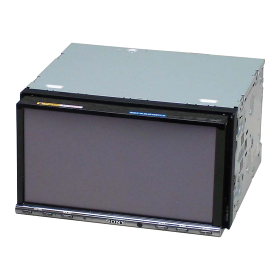
XAV-701BT/741
Photo: XAV-701BT
Model Name Using Similar Mechanism
DVD Section
DVD Mechanism Type
Optical Pick-up Name
Model Name Using Similar Mechanism
OPEN/CLOSE
Section
Monitor Open/Close Block
SPECIFICATIONS
MW/LW
Tuning range:
MW: 531 – 1,602 kHz
LW: 153 – 279 kHz
Antenna (aerial) terminal:
External antenna (aerial) connector
3 (RGB) 480)
Intermediate frequency:
9,124.5 kHz or 9,115.5 kHz/5 kHz
Sensitivity: MW: 26 μV, LW: 46 μV
DVD/CD Player section
Signal-to-noise ratio: 120 dB
Frequency response: 10 – 20,000 Hz
Wow and flutter: Below measurable limit
Harmonic distortion: 0.01%
Region code: Labeled on the bottom of the unit
USB Player section
Interface: USB (High-speed)
Maximum current: 1 A
Wireless Communication*
Communication System:
Bluetooth Standard version 2.1 + EDR
Output:
Bluetooth Standard Power Class 2 (Max. +4 dBm)
Maximum communication range:
Line of sight approx. 10 m (33 ft)*
Frequency band:
2.4 GHz band (2.4000 – 2.4835 GHz)
Modulation method: FHSS
Compatible Bluetooth Profiles*
A2DP (Advanced Audio Distribution Profile) 1.2
AVRCP (Audio Video Remote Control Profile) 1.3
HFP (Handsfree Profile) 1.5
PBAP (Phone Book Access Profile)
OPP (Object Push Profile)
*1 Applies to XAV-701BT only.
*2 The actual range will vary depending on factors
such as obstacles between devices, magnetic
fields around a microwave oven, static electricity,
reception sensitivity, antenna's performance,
operating system, software application, etc.
*3 Bluetooth standard profiles indicate the purpose of
Bluetooth communication between devices.
Power amplifier section
Outputs: Speaker outputs
Speaker impedance: 4 – 8 ohms
Maximum power output: 52 W
General
Outputs:
Video output terminal (rear)
Audio output terminals (front/rear)
Audio output terminals (Z Z) (E (NTSC) model)
Subwoofer output terminal
Power antenna (aerial)/Power amplifier control
terminal (REM OUT) (E (NTSC), E (PAL) and
South African models)
Power antenna (aerial) relay control terminal
(Russian model)
Power amplifier control terminal (Russian model)
South African Model
Inputs:
Illumination control terminal
Remote controller input terminal
Antenna (aerial) input terminal
Parking break control terminal
Microphone input terminal (XAV-701BT only)
Reverse input terminal
Camera input terminal
AUX audio input terminals
AUX video input terminals
USB port
External input terminal (E (PAL), South African
and Russian models)
Power requirements: 12 V DC car battery
(negative ground (earth))
Dimensions: Approx. 178 100 185 mm
1
3
(7
/
4 7
/
in) (w/h/d)
8
8
Mounting dimensions: Approx. 182 111 160 mm
1
3
3
(7
/
4
/
6
/
in) (w/h/d)
4
8
8
Mass: Approx. 2.4 kg (5 lb 5 oz)
Supplied accessories:
Parts for installation and connections (1 set)
1
Microphone (XAV-701BT only)
Remote Commander: RM-X271
Your dealer may not handle some of the above listed
accessories. Please ask the dealer for detailed
information.
2
US and foreign patents licensed from Dolby
Laboratories.
3
:
MPEG Layer-3 audio coding technology and
patents licensed from Fraunhofer IIS and Thomson.
Design and specifications are subject to change
without notice.
Region code
The region system is used to protect software
copyrights.
The region code is located on the bottom of the unit,
and only DVDs labeled with an identical region code
can be played on this unit.
DVDs labeled
can also be played.
ALL
If you try to play any other DVD, the message "Disc
playback prohibited by region code." will appear on the
monitor screen. Depending on the DVD, no region code
4 (at 4 ohms)
may be labeled even though playing the DVD is
prohibited by area restrictions.
E Model
Russian Model
XAV-701BT/741
XAV-701BT
NEW
MG-613XF-187 or MG-614D-189
KHS-360A or TOP1300SE C11
XAV-W1
DB-W07
AV CENTER
Advertisement
Chapters
Table of Contents

Related Manuals for Sony XAV-701BT


Summary of Contents for Sony XAV-701BT
- Page 1 Antenna (aerial) input terminal LW: 153 – 279 kHz System: TFT active matrix Parking break control terminal Antenna (aerial) terminal: Number of pixels: Microphone input terminal (XAV-701BT only) External antenna (aerial) connector 1,152,000 pixels (800 3 (RGB) 480) Reverse input terminal Intermediate frequency:...
- Page 2 ACTIVITY AND/OR WAS OBTAINED FROM A the Bluetooth SIG, Inc. and any use of such marks VIDEO PROVIDER LICENSED BY MPEG LA by Sony Corporation is under license. Other TO PROVIDE MPEG-4 VIDEO. NO LICENSE IS trademarks and trade names are those of their GRANTED OR SHALL BE IMPLIED FOR ANY respective owners.
-
Page 3: Table Of Contents
Note 1: Refer to SUPPLEMENT-1 for the MAIN board of printed wiring board, schematic diagram and electrical parts list of XAV-701BT: E (NTSC) model. EXT-NAVI board is not installation of XAV-701BT: E (NTSC) model. Note 2: Refer to SUPPLEMENT-2 for DVD mechanism deck information of XAV-701BT:E (NTSC) model. -
Page 4: Servicing Notes
Part No. IMPORTANT NOTE FOR REPAIRING (XAV-701BT only) Region Code XAV-701BT contain individual information that the customer reg- istered because it installs the Bluetooth function. When repairing, the data that the customer registered might disap- pear. Have the approval of the customer beforehand. - Page 5 XAV-701BT/741 Ver. 1.2 NOTE THE MAIN BOARD OR SYSTEM CONTROLLER 1. Press the [ ] or [ ] button, and select the alphanumeric char- (IC502) REPLACING acter of “0 to F”. When the complete MAIN board or system controller (IC502) is 2.
- Page 6 XAV-701BT/741 NOTE FOR FLEXIBLE BOARD OF THE OPTICAL PICK-UP When connecting or disconnecting the fl exible board of the opti- cal pick-up to or from the CN2 of the SERVO board, follow the procedure given below. Note: When soldering the short lands, solder within 5 seconds at the tem- perature of soldering iron below 300°C.
-
Page 7: General
Sony más cercano para obtener Es posible que pueda instalar la unidad en algunos más detalles. automóviles japoneses sin el soporte suministrado. En caso de que no pudiera, consulte al distribuidor Sony más Con rayas verdes/negras Izquierdo cercano. - Page 8 The mounting position of the parking brake Z×Z L / R switch cord depends on your car. Consult your car dealer Warning if your car’s ignition or your nearest Sony dealer for further details. has no ACC position SUB OUT REAR AUDIO...
- Page 9 XAV-701BT/741 (Sauth African model) For details on installing the microphone, see “Installing the microphone ( )” on the reverse side. If your car antenna (aerial) is an ISO (International Organization for Standardization) type, use the supplied adaptor to connect it. First connect the car antenna (aerial) to...
- Page 10 The mounting position of the parking brake switch cord depends on your car. Consult your car dealer or your nearest Sony dealer for further details. Clips (not supplied) Clip (not supplied) Installing the microphone...
- Page 11 подключении камеры заднего вида) У деяких автомобілях сигнал може не прийматися належним (жeлтого) стереокомпонентами сила струму в контурі чином. У такому разі зверніться до найближчого дилера Sony. Совет При подсоединении устройства вместе с другими автомобіля, до якого під’єднано пристрій, має бути...
- Page 12 У деяких марках японських автомобілів цей пристрій прилагаемого кронштейна. Если вам не удается это можна встановити без кронштейна з комплекту Желтый Желтый сделать, обратитесь за консультацией к дилеру Sony. постачання. Якщо це зробити не вдається, зверніться Жовтий Жовтий Установлення мікрофона...
-
Page 13: Disassembly
XAV-701BT/741 Ver. 1.2 SECTION 3 DISASSEMBLY • This set can be disassembled in the order shown below. 3-1. DISASSEMBLY FLOW 3-2. FRONT PANEL BLOCK (Page 14) 3-3. PANEL BASE BLOCK (Page 15) 3-4. D-SUB7 BOARD 3-5. CHASSIS DISPLAY (Page 15) -
Page 14: Front Panel Block
XAV-701BT/741 Note: Follow the disassembly procedure in the numerical order given. 3-2. FRONT PANEL BLOCK front panel block 3 hook spring 1 Turn the power on and press the eject button to open the front panel block. Note 1: When drawing out the front panel, fundamentally turn on the power and press the Eject button to open. -
Page 15: Panel Base Block
XAV-701BT/741 Ver. 1.2 3-3. PANEL BASE BLOCK 4 claw 4 claw 3 connector 2 two screws (PTT2.6 (CN7302) – Front panel block rear side view – 1 two screws (Z M1.7 2.5) Note: These screws are deleted from the midway of production. -
Page 16: Chassis Display Block
XAV-701BT/741 3-5. CHASSIS DISPLAY BLOCK 4 LCD flexible board (CN4000) (Note 1) 3 touch panel flexible board 7 claw (CN4500) (Note 1) 2 flexible flat cable (20 core) (CN9509) (Note 1) 5 two screws (Z S1.7 1 LCD flexible board... -
Page 17: Display Board
XAV-701BT/741 3-6. DISPLAY BOARD (XAV-701BT) ow o i s all he shield (A ) block Note: Check that the mark of the shield (AP) and the mark of the DISPLAY board are the same directions. 2 Bend the claw in the shield (AP) block 1 Remove the solder. -
Page 18: Liquid Crystal Display Panel (Lcd1)
XAV-701BT/741 3-7. LIQUID CRYSTAL DISPLAY PANEL (LCD1) 1 claw 2 Remove the LCD block in the direction of an arrow. 5 liquid crystal display panel (LCD1) 4 sheet (LCD) – Front panel block rear side view – (XAV-701BT) 3 two cushions (LCD) -
Page 19: Key7 Board, Cover (Button)
XAV-701BT/741 Ver. 1.1 3-9. KEY7 BOARD, COVER (BUTTON) 8 button (EJECT7) 5 boss 9 filter (IR7) 2 Remove the cover (button) block in the direction of an arrow. 4 claw 5 boss 0 cover (button) 7 button (VOL) 6 KEY7 board... -
Page 20: Sub Panel Block
XAV-701BT/741 Ver. 1.1 3-11. SUB PANEL BLOCK 1 screw (PTT2.6 2 claw 2 claw 2 two claws 1 screw (PTT2.6 4 sub panel block 2 two claws... -
Page 21: Dvd Mechanism Deck (Mg-613Xf-187)
XAV-701BT/741 Ver. 1.1 3-12. DVD MECHANISM DECK (MG-613XF-187) 4 DVD mechanism deck (MG-613XF-187) 3 flexible flat cable (60 core) (CN101) 1 screw (PTT2.6 1 two screws (PTT2.6 1 screw (PTT2.6 Note: When you install the flexible flat cable, please install them correctly. -
Page 22: Bracket (Cover)
XAV-701BT/741 3-13. BRACKET (COVER) 1 three screws (PTT2.6 2 bracket (cover) 3-14. CONNECTION CORD FOR AUTOMOBILE ( ) (CNC201, CNC202) 6 connection cord for automobile ( (CNC202) connection cord for automobile ) (CNC201) 4 screw connection cord for (PTT2.6 automobile (... -
Page 23: Connector Assy (Nv1) (E (Pal), South African, Russian Models)
XAV-701BT/741 Ver. 1.2 3-15. CONNECTOR ASSY (NV1) (E (PAL), South African, Russian models) 5 claw EXT-NAVI board 6 connector assy (NV1) 3 connector (CN940) 2 connector 4 two screws (CN701) (PTT2.6 lead pin MAIN board 1 Remove the wire from lead pin. -
Page 24: Main Board Block
XAV-701BT/741 3-17. MAIN BOARD BLOCK 5 two screws (PTT2.6 6 ground point screw 6 ground point screw (PTT2.6 (PTT2.6 6 ground point screw (PTT2.6 5 two screws (PTT2.6 7 MAIN board block 3 flexible printed wiring board (60 pin) (FPB1) -
Page 25: Dc Fan (25X25) (M801), Main Board
XAV-701BT/741 Ver. 1.2 3-18. DC FAN (25X25) (M801), MAIN BOARD Note: When the complete MAIN board is replaced, the destination setting is necessary. Refer to “NOTE THE MAIN BOARD OR SYSTEM CONTROLLER (IC502) REPLACING” on page 5. thermal conductive thermal conductive... -
Page 26: Monitor Open/Close Block (Db-W07)
XAV-701BT/741 3-20. MONITOR OPEN/CLOSE BLOCK (DB-W07) flexible flat cable (20 core) (FFC2) 2 claw tape 1 screw (PTT2.6 4 tape guide line guide line 3 bracket (back) 5 flexible flat cable (20 core) 6 tape 8 screw (T) (FFC2) (CN7002) -
Page 27: Dvd Mechanism Deck Block
XAV-701BT/741 3-21. DVD MECHANISM DECK BLOCK 5 bracket (DVD) 6 DVD mechanism deck block 4 screw (PTT2.6 2 screw (PTT2.6 3 shield (613S) 1 two precision screws (P1.7 2.2) 3-22. SERVO BOARD 3 OP flexible board (CN2) Note: When disconnecting the OP flexible board from of the connector. -
Page 28: Chassis (T612Z) Sub Assy, Sensor Board
XAV-701BT/741 3-23. CHASSIS (T612Z) SUB ASSY, SENSOR BOARD 1 two precision screws 3 claw (P1.7 2.2) 1 two precision screws (P1.7 2.2) WHITE BLACK 4 chassis (T612Z) sub assy 5 Remove the three solders of SENSOR board wire. 6 SENSOR borad 2 claw 3-24. -
Page 29: Electrical Adjustments
XAV-701BT/741 SECTION 4 ELECTRICAL ADJUSTMENTS 2. Insert the 5pin cable into the connector of the MAIN board MONITOR SECTION (CN501). If any of the following parts was replaced, execute the “Flicker Note: Connect 5pin cable after removing the front panel block and DVD Adjustment”... - Page 30 XAV-701BT/741 2. FLICKER ADJUSTMENT Example of characteristic: Note 1: Perform adjustment of NTSC/PAL separately. Procedure: 1. The setting of “1. SETTINGS” is completed. 2. Input the NTSC or PAL white 40% raster signal from AUX2 IN jack on the rear side of main unit.
- Page 31 XAV-701BT/741 Check Location: SERVO SECTION – SERVO Board (Side B) – If any of the following parts was replaced, perform the “IOP Check” as mentioned below. • Optical pick-up block (chassis (OP, ZA) complete assy) TP47 • Complete SERVO board...
-
Page 32: Diagrams
XAV-701BT/741 SECTION 5 DIAGRAMS 5-1. BLOCK DIAGRAM - SERVO Section - OPTICAL PICK-UP BLOCK R-ch is omitted due to same as L-ch. DVD PROCESSOR D/A CONVERTER (KHS-360A) SIGNAL PATH : AUDIO 157 RFP VO1 FL AOUT0 6 DATA1 AOUT1 11 DATA2 RF–... -
Page 33: Block Diagram - Audio Section
XAV-701BT/741 Ver. 1.2 5-2. BLOCK DIAGRAM - AUDIO Section - J702 (1/3) LINE R-ch is omitted due to same as L-ch. IC351 SIGNAL PATH R-CH : AUDIO INPUT SELECTOR, : TUNER ELECTRICAL VOLUME MUTING Q311 IC301 : NAVI (Page 32) -
Page 34: Block Diagram - Video, Panel, Power Supply Section
XAV-701BT/741 Ver. 1.2 5-3. BLOCK DIAGRAM - VIDEO, PANEL, POWER SUPPLY Section - USB INTERFACE IC201 M801 CNC201 SYSRSTB (FAN) DISPLAY BOARD X203 REGULATOR +1.9V 30MHz KEY7 BOARD D +1.9V REGULATOR IC801 (2/2) IC101 LCD1 DR +5V 33 MECHA_5V LIQUID CRYSTAL... - Page 35 XAV-701BT/741 Ver. 1.2 THIS NOTE IS COMMON FOR PRINTED WIRING BOARDS AND SCHEMATIC DIAGRAMS. • Circuit Boards Location (In addition to this, the necessary note is printed in each block.) For Printed Wiring Boards. For Schematic Diagrams. Note: Note: SERVO board •...
-
Page 36: Printed Wiring Boards - Servo Section
XAV-701BT/741 5-4. PRINTED WIRING BOARDS - SERVO Section - • See page 35 for Circuit Boards Location. • : Uses unleaded solder. OPTICAL PICK-UP BLOCK (KHS-360A) SERVO BOARD (SIDE B) TP45 TP32 TP44 R231 TP30 TP47 TP51 (IOPCD) (IOPDVD) TP43... -
Page 37: Schematic Diagram - Servo Section (1/3)
XAV-701BT/741 5-5. SCHEMATIC DIAGRAM - SERVO Section (1/3) - • See page 52 for IC Block Diagrams. SERVO BOARD (1/3) FB45 TP23 LIMIT SW GND FCS+ LIMIT SW TP24 TRK+ FB44 TP59 TP25 4.7k TRK- FB37 TP26 COIL V TP50... -
Page 38: Schematic Diagram - Servo Section (2/3)
XAV-701BT/741 5-6. SCHEMATIC DIAGRAM - SERVO Section (2/3) - • See page 46 for Waveforms. • See page 58 for IC Pin Function Description. SERVO (Page 39) BOARD (3/3) SERVO BOARD (2/3) OP_GAIN 27MHz (Page 37) SERVO R116 BOARD 4.7k... -
Page 39: Schematic Diagram - Servo Section (3/3)
XAV-701BT/741 5-7. SCHEMATIC DIAGRAM - SERVO Section (3/3) - • See page 52 for IC Block Diagrams. SERVO BOARD (3/3) TP130 AMCLK ALRCLK ABCLK LRCK DOUT R105 IC B/D DGND C118 AGND VINL D/A CONVERTER AIN_R VREF VINR PCM1680DBQ AIN_L 4.7k... -
Page 40: Printed Wiring Board - Main Board (Component Side)
XAV-701BT/741 5-8. PRINTED WIRING BOARD - MAIN Board (Component Side) - • See page 35 for Circuit Boards Location. • : Uses unleaded solder. MAIN BOARD (COMPONENT SIDE) R300 R343 R347 VDR311 R314 VDR309 VDR315 R310 R313 R872 VDR301 C820... -
Page 41: Main Board (Conductor Side)
XAV-701BT/741 5-9. PRINTED WIRING BOARD - MAIN Board (Conductor Side) - • See page 35 for Circuit Boards Location. • : Uses unleaded solder. CNC1 J702 AUX1 REAR FRONT AUX2 REAR CAMERA MAIN BOARD AUDIO IN AUDIO OUT AUDIO OUT... -
Page 42: Schematic Diagram - Main Board (1/4)
XAV-701BT/741 Ver. 1.1 5-10. SCHEMATIC DIAGRAM - MAIN Board (1/4) - • See page 52 for IC Block Diagrams. M801 MAIN BOARD (1/4) CN803 (FAN) R878 IC B/D IC801 R879 R836 C856 C867 D829 C375 R953 Q852 0.47 0.47 RKZ18B2KGP1... -
Page 43: Schematic Diagram - Main Board (2/4)
XAV-701BT/741 5-11. SCHEMATIC DIAGRAM - MAIN Board (2/4) - • See page 46 for Waveforms. • See page 52 for IC Block Diagrams. MAIN BOARD (2/4) MAIN BOARD (3/4) (Page C101 C345 C346 R338 R359 C323 2.2k 2.2k C105 0.01... -
Page 44: Schematic Diagram - Main Board (3/4)
XAV-701BT/741 5-12. SCHEMATIC DIAGRAM - MAIN Board (3/4) - • See page 46 for Waveforms. • See page 52 for IC Block Diagrams. • See page 58 for IC Pin Function Description. MAIN BOARD (3/4) BUS4 REG+3.3V_2 MAIN M_CVBS_GND BOARD... -
Page 45: Schematic Diagram - Main Board (4/4)
XAV-701BT/741 5-13. SCHEMATIC DIAGRAM - MAIN Board (4/4) - • See page 46 for Waveforms. • See page 52 for IC Block Diagrams. • See page 58 for IC Pin Function Description. MAIN BOARD (4/4) IC703 IC B/D VIDEO SELECT... -
Page 46: Printed Wiring Board - Ext-Navi Board
XAV-701BT/741 • Waveforms 5-14. PRINTED WIRING BOARD - EXT-NAVI Board - • See page 35 for Circuit Boards Location. • : Uses unleaded solder. – SERVO Board – – MAIN Board – IC4 <zvb (XO) IC401 1 (BST) EXT-NAVI BOARD... -
Page 47: Schematic Diagram - Ext-Navi Board
XAV-701BT/741 5-15. SCHEMATIC DIAGRAM - EXT-NAVI Board - • See page 52 for IC Block Diagrams. EXT-NAVI BOARD C603 R627 R647 R607 R619 JL604 R622 R623 R608 R620 4.7k JL605 JL601 R609 R621 JL606 CN601 R610 IC B/D JL607 IC601... -
Page 48: Printed Wiring Board - Motor Board
XAV-701BT/741 5-16. PRINTED WIRING BOARD - MOTOR Board - • See page 35 for Circuit Boards Location. • : Uses unleaded solder. MOTOR BOARD MOTOR BOARD (SIDE A) (SIDE B) C7009 R7012 S7002 MONITOR CLOSE DETECT (CHASSIS) JL7003 C7010 R7034... -
Page 49: Schematic Diagram - Motor Board
XAV-701BT/741 5-17. SCHEMATIC DIAGRAM - MOTOR Board - • See page 52 for IC Block Diagrams. MOTOR BOARD CN7002 FP_IDET IDET JL7016 TEMP R7026 JL7015 M_LOW M_LOW R7027 JL7014 M_MID M_MID R7028 JL7013 OPEN R7029 JL7012 CLOSE JL7011 M_ON M_ON... -
Page 50: Printed Wiring Boards - Panel Section
XAV-701BT/741 5-18. PRINTED WIRING BOARDS - PANEL Section - • See page 35 for Circuit Boards Location. • : Uses unleaded solder. D-SUB7 BOARD D-SUB7 BOARD (SIDE A) (SIDE B) CN7301 (CHASSIS) CN7302 R7313 R7312 R7311 R7314 (11) (11) 1-886-024-... -
Page 51: Schematic Diagram - Panel Section
XAV-701BT/741 5-19. SCHEMATIC DIAGRAM - PANEL Section - D-SUB7 BOARD CN7301 VBUS_GND VBUS VBUS VBUS VBUS_GND USB_D– USB_D– USB_D+ USB_D+ DISPLAY KEY7 BOARD BOARD VBUS_GND LCD1 TPN1 LIQUID TOUCH CRYSTAL PANEL +7.5V DISPLAY PANEL +7.5V +7.5V +7.5V CN7302 +7.5V BL_GND... - Page 52 XAV-701BT/741 • IC Block Diagrams IC6 PCM1680DBQ – SERVO Board – ZERO1 1 ZERO2 IC1 BH5510KV-E2 SYSTEM CLOCK SYSTEM ZERO MANAGER CLOCK DETECT POWER SUPPLY 36 35 33 32 VOUT1 OUTPUT AMP AND VREF 37 MS/ADR 2 CONVERTER LOW-PASS FILTER...
- Page 53 XAV-701BT/741 IC301 BD3467FV-E2 FADER FADER BOOST OUTC FADER FADER A1 1 BOOST OUTS A2 2 FADER FADER B1 3 OUTR1 BOOST B2 4 FADER FADER OUTR2 BOOST CP1 5 FADER FADER CN 6 OUTF1 BOOST CP2 7 FADER FADER OUTF2...
- Page 54 XAV-701BT/741 IC302 NJW1240V (TE2) MUTING OUT1 IN1 1 MUTING OUT2 IN2 2 MUTING OUT3 IN3 3 MUTING OUT4 IN4 4 MUTING OUT5 IN5 5 MUTING OUT6 IN6 6 POP NOISE MUTE 7 SUPPRESSION GAIN SELECT GAIN 8 6 dB/8 dB...
- Page 55 XAV-701BT/741 IC401, 431 OZ529IGN-A1-TR BST 1 VREF OSCILLATOR LX 2 REFERENCE GENERATOR OVER CURRENT PROTECTION GNDA VIN 3 EN_SYS 4 USBOUT 5 FB_USB 6 SS_SYS ADJUSTMENT GENERATOR CHARGE EN_USB PUMP VIC_USB USBIN OVER-CURRENT ISET_USB LIMIT VOUT_SYS (USBIN) UVLS FAULT PROTECTION –...
- Page 56 XAV-701BT/741 IC461 SI-8205NHG-TL REG_DRV ISNS GND 1 ICSPWM SS_REF ENABLE/ CURRENT EN/SS 2 ICSOCP POWER SOFT-START SENSE STANDBY STAGE VIN 3 OVER CURRENT REGULATOR PROTECT COMPARATOR REGULATOR VINOK UNDER PHASE VOLTAGE CURRENT RES_PH PHASE GATE CBCHG BS_CHG LOCK OUT LSOFF...
- Page 57 XAV-701BT/741 IC801 TDF8556AJ/N5 I2C_SIO OUT-FL– C BUS I2C_SCK OUT-FL+ OUT-RL– P-GND1 OUT-RL+ IN-RL IN-FL S-GND PROTECTION/ DIAGNOSTIC IN-FR IN-RR BEEP OUT-RR+ P-GND3 OUT-RR– OUT-FR+ STANDBY/ MUTE OUT-FR– CHIP DETECT/ P-GND4 DIAGNOSTIC TEMPERATURE PROTECTION DIAG ENABLE LOGIC SWITCH ANT-REM CRES AMP-REM...
- Page 58 XAV-701BT/741 • IC Pin Function Description SERVO BOARD IC4 ZR36988HQCG-AN (DVD PROCESSOR) Pin No. Pin Name Description MEMDAT2 to MEMDAT7, 1 to 9 Two-way data bus with the fl ash memory MEMDAT13 to MEMDAT15 VDDC Power supply terminal (+1.8V) VDDP Power supply terminal (+3.3V)
- Page 59 XAV-701BT/741 Pin No. Pin Name Description RAMDAT10 to RAMDAT12, 78 to 83 Two-way data bus with the SD-RAM RAMDAT5 to RAMDAT3 VDDP Power supply terminal (+3.3V) GNDC Ground terminal RAMDAT13, 86, 87 Two-way data bus with the SD-RAM RAMDAT2 VDDC Power supply terminal (+1.8V)
- Page 60 XAV-701BT/741 Pin No. Pin Name Description DAC4 Analog YUV video signal (Y) output to the panel section VDDDAC Power supply terminal (+3.3V) DAC3 Analog composite video signal (CVBS) output to the video processor and REAR OUT jack DAC2 Analog YUV video signal (V) output to the panel section VDDDAC Power supply terminal (+3.3V)
- Page 61 XAV-701BT/741 MAIN BOARD IC201 PD720114GA-YEU-A-SAK (USB INTERFACE) Pin No. Pin Name Description VDD25OUT Internal regulator power supply voltage (+2.5V) output terminal VSSREG Ground terminal (for internal regulator) 3 to 6 LED4 to LED1 Not used GREEN Not used AMBER Not used VDD33 Power supply terminal (+3.3V)
- Page 62 XAV-701BT/741 Ver. 1.2 MAIN BOARD IC502 R5F3650NCDZ97FB (SYSTEM CONTROLLER) Pin No. Pin Name Description SPEED_IN Speed pulse signal input terminal Not used SIRCS SIRCS signal input from the panel section MODEL_SEL1 to 3 to 5 Model setting terminal MODEL_SEL3 BYTE External data bus width selection signal input terminal Fixed at “L”...
- Page 63 XAV-701BT/741 Pin No. Pin Name Description MECHA_CTS Clear to send signal output to the DVD processor IPOD_DET Not used AP_CNT1 Not used Power supply terminal (+3.3V) AP_RESET Reset signal output to the panel section “L”: reset Ground terminal AP_ON Power supply on/off control signal output to the DC/DC converter “H”: power on...
-
Page 64: Exploded Views
XAV-701BT/741 Ver. 1.2 SECTION 6 EXPLODED VIEWS Note: • -XX and -X mean standardized parts, so • The mechanical parts with no reference • Abbreviation they may have some difference from the number in the exploded views are not sup- : Russian model original one. -
Page 65: Front Panel Section
SCREW +Z B1.4X4 A-1871-832-A D-SUB7 BOARD, COMPLETE 4-434-437-11 SHEET (HEAT), TRANSFER, T1.2 (XAV-741) 3-042-244-51 SCREW (T) 4-434-436-11 SHEET (HEAT), TRANSFER, T0.5 (XAV-701BT) A-1871-829-A DISPLAY BOARD, COMPLETE 4-298-927-01 SHEILD (AP) (XAV-701BT) (XAV-701BT: E (PAL), SAF, RU) 4-446-848-01 GASKET (BT), H2.5 (XAV-701BT) -
Page 66: Key7 Board Section
Part No. Description Remark 2-897-564-01 SCREW +Z B1.4X4 4-298-940-01 FILTER (IR7) ( ) 4-298-933-01 PANEL (FRONT7) (XAV-701BT) (Former type) 4-298-941-01 COVER (BUTTON) 4-298-933-02 PANEL (FRONT7) (XAV-701BT) (New type) 4-298-936-01 BUTTON (VOL) (–, +, DSPL) 4-298-933-11 PANEL (FRONT7) (XAV-741) (Former type) -
Page 67: Chassis Main Section
XAV-701BT/741 Ver. 1.2 6-4. CHASSIS MAIN SECTION not supplied CNC202 CNC201 not supplied EXT-NAVI board not supplied (E(APL), SAF, RU) not supplied MAIN board section motor section FPB1 not supplied (LID (MAIN) board) not supplied not supplied Ref. No. Part No. -
Page 68: Main Board Section
“NOTE THE MAIN BOARD OR SYSTEM CONTROLLER (IC502) REPLACING” on page 5. Ref. No. Part No. Description Remark Ref. No. Part No. Description Remark A-1871-808-A MAIN BOARD, COMPLETE (XAV-701BT: SAF) CN01 A-1878-198-A TUX-DSP02 (FM/AM TUNER UNIT) A-1871-809-A MAIN BOARD, COMPLETE (Included in MAIN board) (XAV-701BT: E (PAL), RU) F801 1-532-877-11... -
Page 69: Motor Section
XAV-701BT/741 6-6. MOTOR SECTION not supplied not supplied FFC2 not supplied MOTOR board (including monitor open/close motor (M7001)) monitor open/close motor (M7001) Ref. No. Part No. Description Remark Ref. No. Part No. Description Remark A-1871-803-A MOTOR BOARD, COMPLETE 2-319-258-02 DB-W07 (MONITOR OPEN/CLOSE BLOCK) 4-410-504-01 SCREW (+PTT 2.6X6), GROUND POINT... -
Page 70: Dvd Mechanism Deck Section (Mg-613Xf-187)
XAV-701BT/741 6-7. DVD MECHANISM DECK SECTION (MG-613XF-187) not supplied loading motor (M1) not supplied (SENSOR board) not supplied FFC1 Ref. No. Part No. Description Remark Ref. No. Part No. Description Remark A-1211-766-B CHASSIS (T612Z) SUB ASSY 4-162-647-01 SCREW, TOOTHED LOCK +Z M1.7X2.5... -
Page 71: Electrical Parts List
Ref. No. Part No. Description Remark Ref. No. Part No. Description Remark A-1871-829-A DISPLAY BOARD, COMPLETE < TRANSISTOR > (XAV-701BT: E (PAL), SAF, RU) A-1871-830-A DISPLAY BOARD, COMPLETE (XAV-741) Q601 6-552-430-01 TRANSISTOR DRC5114E0L A-1905-945-A DISPLAY BOARD, COMPLETE Q602 6-552-430-01 TRANSISTOR... - Page 72 XAV-701BT/741 MAIN Ref. No. Part No. Description Remark Ref. No. Part No. Description Remark A-1871-808-A MAIN BOARD, COMPLETE (XAV-701BT: SAF) C316 1-100-597-91 CERAMIC CHIP 0.1uF A-1871-809-A MAIN BOARD, COMPLETE C317 1-100-381-11 ELECT CHIP 10uF (XAV-701BT: E (PAL), RU) C318 1-112-746-11 CERAMIC CHIP 4.7uF...
-
Page 73: Ref. No
XAV-701BT/741 Ver. 1.1 MAIN Ref. No. Part No. Description Remark Ref. No. Part No. Description Remark C385 1-115-412-11 CERAMIC CHIP 680PF C519 1-100-597-91 CERAMIC CHIP 0.1uF C386 1-112-746-11 CERAMIC CHIP 4.7uF 6.3V C521 1-162-918-11 CERAMIC CHIP 18PF C387 1-162-921-11 CERAMIC CHIP 33PF... -
Page 74: Not Supplied
1-162-970-11 CERAMIC CHIP 0.01uF FB303 1-414-385-21 INDUCTOR, FERRITE BEAD C918 1-162-970-11 CERAMIC CHIP 0.01uF FB307 1-500-329-21 INDUCTOR, FERRITE BEAD (XAV-701BT) C951 1-112-513-91 CERAMIC CHIP 1200PF FB308 1-500-329-21 INDUCTOR, FERRITE BEAD (XAV-701BT) FB309 1-500-329-21 INDUCTOR, FERRITE BEAD < FM/AM TUNER UNIT/CONNECTOR >... - Page 75 XAV-701BT/741 MAIN Ref. No. Part No. Description Remark Ref. No. Part No. Description Remark R116 1-216-295-91 SHORT CHIP < COIL > R117 1-216-295-91 SHORT CHIP R118 1-216-864-11 SHORT CHIP 1-400-073-21 INDUCTOR 4.7uH R130 1-216-864-11 SHORT CHIP L101 1-481-182-21 INDUCTOR 22uH...
- Page 76 METAL CHIP 1/10W R512 1-216-864-11 SHORT CHIP R379 1-216-813-11 METAL CHIP 1/10W R513 1-216-864-11 SHORT CHIP R380 1-216-864-11 SHORT CHIP 0 (XAV-701BT) R514 1-216-864-11 SHORT CHIP R383 1-216-864-11 SHORT CHIP R515 1-216-809-11 METAL CHIP 1/10W R384 1-216-809-11 METAL CHIP 1/10W...
- Page 77 XAV-701BT/741 MAIN Ref. No. Part No. Description Remark Ref. No. Part No. Description Remark R551 1-216-817-11 METAL CHIP 1/10W R817 1-216-841-11 METAL CHIP 1/10W R552 1-216-809-11 METAL CHIP 1/10W R818 1-216-829-11 METAL CHIP 4.7K 1/10W R553 1-216-845-11 METAL CHIP 100K...
-
Page 78: Motor Board, Complete Mo2
XAV-701BT/741 MAIN MOTOR SENSOR SERVO Ref. No. Part No. Description Remark Ref. No. Part No. Description Remark < VIBRATOR > R7008 1-216-825-11 METAL CHIP 2.2K 1/10W R7009 1-216-134-00 METAL CHIP 1/8W X203 1-814-367-11 QUARTZ CRYSTAL UNITS (30 MHz) R7010 1-216-134-00... - Page 79 XAV-701BT/741 SERVO Ref. No. Part No. Description Remark Ref. No. Part No. Description Remark 1-125-777-11 CERAMIC CHIP 0.1uF 1-164-936-11 CERAMIC CHIP 680PF 1-164-934-11 CERAMIC CHIP 330PF 1-165-708-11 ELECT CHIP 47uF 6.3V 1-164-934-11 CERAMIC CHIP 330PF 1-125-777-11 CERAMIC CHIP 0.1uF 1-164-937-11 CERAMIC CHIP 0.001uF...
- Page 80 XAV-701BT/741 SERVO Ref. No. Part No. Description Remark Ref. No. Part No. Description Remark < FERRITE BEAD/RESISTOR > < FERRITE BEAD > 1-457-421-21 INDUCTOR, FERRITE BEAD (1608) 1-469-407-22 INDUCTOR, FERRITE BEAD 1-457-421-21 INDUCTOR, FERRITE BEAD (1608) 1-469-407-22 INDUCTOR, FERRITE BEAD...
-
Page 81: Cable, Flexible Flat (20 Core)
XAV-701BT/741 Ver. 1.2 SERVO Ref. No. Part No. Description Remark Ref. No. Part No. Description Remark 1-218-961-11 METAL CHIP 4.7K 1/16W R230 1-218-977-11 METAL CHIP 100K 1/16W 1-218-961-11 METAL CHIP 4.7K 1/16W R231 1-218-977-11 METAL CHIP 100K 1/16W 1-218-941-81 METAL CHIP... - Page 82 POWER CORD (ISO) 4-413-197-01 BRACKET (FRAME) (1 piece) X-2177-512-1 SCREW ASSY (2DIN) (8 pieces, 1 set) 1-542-870-11 MICROPHONE UNIT (Including HOLDER, DOUBLE-SIDED TAPE) (XAV-701BT) POWER CORD CONNECTION CORD (20P) COLLAR KEY (FRAME) +K S3 × 8 +K 5 × 8...
- Page 83 XAV-701BT/741 E Model Russian Model SERVICE MANUAL XAV-701BT/741 South African Model XAV-701BT Ver. 1.2 2012.11 SUPPLEMENT-1 File this supplement with the service manual. Subject: Change of the EXT-NAVI and MAIN boards (Suffi x-14) The EXT-NAVI and MAIN boards have been changed in the midway of pro- duction.
- Page 84 XAV-701BT/741 2. DIAGRAMS THIS NOTE IS COMMON FOR PRINTED WIRING BOARDS AND SCHEMATIC DIAGRAMS. (In addition to this, the necessary note is printed in each block.) For Printed Wiring Boards. For Schematic Diagrams. Note: Note: • X : Parts extracted from the component side.
- Page 85 XAV-701BT/741 Ver. 1.2 2-1. PRINTED WIRING BOARD - MAIN Board (Component Side) - • : Uses unleaded solder. MAIN BOARD (COMPONENT SIDE) R300 R343 R347 VDR311 R314 VDR309 VDR315 R310 R313 R872 VDR301 C820 R839 D307 C818 VDR312 R871 C834...
- Page 86 XAV-701BT/741 Ver. 1.2 2-2. PRINTED WIRING BOARD - MAIN Board (Conductor Side) - • : Uses unleaded solder. CNC1 J702 AUX1 REAR FRONT AUX2 REAR CAMERA MAIN BOARD AUDIO IN AUDIO OUT AUDIO OUT AUDIO IN (CONDUCTOR SIDE) REVERSE J302...
- Page 87 XAV-701BT/741 Ver. 1.2 2-3. SCHEMATIC DIAGRAM - MAIN Board (1/4) - M801 MAIN BOARD (1/4) CN803 (FAN) R878 IC801 R879 R836 C856 C867 D829 C375 R953 Q852 0.47 0.47 RKZ18B2KGP1 POWER AMP, REGULATOR DSC500100L IC801 10 11 12 13 14 15 16 17 18 19 20 21 22 23 24 25 26 27 28 29 30 31 32 33 34 35 36 37...
- Page 88 XAV-701BT/741 Ver. 1.2 2-4. SCHEMATIC DIAGRAM - MAIN Board (2/4) - • See page 9 for IC Block Diagrams. MAIN BOARD (2/4) MAIN BOARD (3/4) (Page C105 R123 C101 0.01 R122 R121 C345 C346 R338 R359 C323 2.2k 2.2k OUTC...
- Page 89 XAV-701BT/741 Ver. 1.2 2-5. SCHEMATIC DIAGRAM - MAIN Board (3/4) - • See page 9 for IC Block Diagrams. MAIN BOARD (3/4) BUS4 REG+3.3V_2 MAIN M_CVBS_GND BOARD (4/4) VIDEO_COMP (Page 8) CN101 CL114 VIDEO_COMP MAIN VGND BOARD CL112 BOOT (1/4)
- Page 90 XAV-701BT/741 Ver. 1.2 2-6. SCHEMATIC DIAGRAM - MAIN Board (4/4) - • See page 9 for IC Block Diagrams. MAIN BOARD (4/4) IC703 VIDEO SELECT IC703 CAMERA NJM41050 C731 VIN1 SSIGV R733 FB331 R701 VSAG VIN2 FB332 R702 J702 SREFV...
- Page 91 XAV-701BT/741 Ver. 1.2 • IC Block Diagrams 2-7. PRINTED WIRING BOARD - EXT-NAVI Board (E (PAL), South African, Russian models) - • : Uses unleaded solder. – MAIN Board – IC101 BD00GA5WEFJ-E2 IC103 BD00GA3WEFJ-E2 EXT-NAVI BOARD IC105 BD00GC0WEFJ-SE2 IC702 NJM2534M (TE2)
- Page 92 XAV-701BT/741 Ver. 1.2 2-8. SCHEMATIC DIAGRAM - EXT-NAVI Board (E (PAL), South African, Russian models) - EXT-NAVI BOARD C603 R627 R647 R607 R619 JL604 R622 R623 R608 R620 4.7k JL605 JL601 R609 R621 JL606 CN601 R610 JL607 IC601 C602 R611...
- Page 93 SHORT CHIP C609 1-100-611-91 CERAMIC CHIP 22uF 6.3V ************************************************************ C610 1-114-582-91 CERAMIC CHIP 0.1uF A-1871-808-A MAIN BOARD, COMPLETE (XAV-701BT: SAF) < CONNECTOR > A-1871-809-A MAIN BOARD, COMPLETE (XAV-701BT: E (PAL), RU) CN601 1-842-501-11 CONNECTOR (BUS) (EXT) A-1871-810-A MAIN BOARD, COMPLETE (XAV-741)
- Page 94 XAV-701BT/741 Ver. 1.2 MAIN Ref. No. Part No. Description Remark Ref. No. Part No. Description Remark C122 1-100-159-91 CERAMIC CHIP 22uF 6.3V C345 1-162-921-11 CERAMIC CHIP 33PF C346 1-162-921-11 CERAMIC CHIP 33PF C201 1-100-597-91 CERAMIC CHIP 0.1uF C348 1-162-970-11 CERAMIC CHIP 0.01uF...
- Page 95 XAV-701BT/741 MAIN Ref. No. Part No. Description Remark Ref. No. Part No. Description Remark C414 1-114-323-11 CERAMIC CHIP 0.01uF C807 1-100-591-91 CERAMIC CHIP 1uF C415 1-100-597-91 CERAMIC CHIP 0.1uF C809 1-107-907-11 ELECT 22uF C431 1-100-055-21 CERAMIC CHIP 22uF C810 1-125-891-11 CERAMIC CHIP 0.47uF...
- Page 96 Ref. No. Part No. Description Remark Ref. No. Part No. Description Remark < FM/AM TUNER UNIT/CONNECTOR > FB307 1-500-329-21 INDUCTOR, FERRITE BEAD (XAV-701BT) FB308 1-500-329-21 INDUCTOR, FERRITE BEAD (XAV-701BT) CN01 A-1878-198-A TUX-DSP02 (FM/AM TUNER UNIT) FB309 1-500-329-21 INDUCTOR, FERRITE BEAD CN101...
- Page 97 XAV-701BT/741 Ver. 1.2 MAIN Ref. No. Part No. Description Remark Ref. No. Part No. Description Remark L705 1-400-675-11 INDUCTOR 10uH R300 1-481-746-11 SDM EMI FERRITE L801 1-456-617-11 COIL, CHOKE R301 1-469-667-21 FERRITE, EMI (SMD) (1608) R302 1-469-667-21 FERRITE, EMI (SMD) (1608)
- Page 98 METAL CHIP 100K 1/10W R379 1-216-813-11 METAL CHIP 1/10W R520 1-218-977-11 METAL CHIP 100K 1/16W R380 1-216-864-11 SHORT CHIP 0 (XAV-701BT) R521 1-216-049-11 METAL CHIP 1/10W R383 1-216-864-11 SHORT CHIP R522 1-216-845-11 METAL CHIP 100K 1/10W R384 1-216-809-11 METAL CHIP...
- Page 99 XAV-701BT/741 Ver. 1.2 MAIN Ref. No. Part No. Description Remark Ref. No. Part No. Description Remark R570 1-216-845-11 METAL CHIP 100K 1/10W R871 1-481-746-11 SDM EMI FERRITE R571 1-216-845-11 METAL CHIP 100K 1/10W R872 1-481-746-11 SDM EMI FERRITE R572 1-216-845-11...
- Page 100 XAV-701BT/741 MEMO...
- Page 101 XAV-701BT/741 E Model Russian Model SERVICE MANUAL XAV-701BT/741 South African Model XAV-701BT Ver. 1.2 2012.11 SUPPLEMENT-2 File this supplement with the service manual. File this supplement with the service manual. Subject: Change of DVD mechanism deck (MG-614D-189) The DVD mechanism deck for this unit has been changed the MG- 614D-189 from MG-613XF-187 in the midway of production.
-
Page 102: Servicing Notes
XAV-701BT/741 TABLE OF CONTENTS SERVICING NOTES DIAGRAMS ..........4-1. Block Diagram - SERVO Section - ........ DISASSEMBLY 4-2. Printed Wiring Boards - SERVO Section - ..... 11 4-3. Schematic Diagram - SERVO Section (1/2) - ....12 2-1. Disassembly Flow ............ -
Page 103: Disassembly
XAV-701BT/741 2. DISASSEMBLY • This set can be disassembled in the order shown below. 2-1. DISASSEMBLY FLOW DVD MECHANISM DECK (MG-614D-189) 2-2. SERVO BOARD-1 2-5. CHASSIS (T, 614) SUB ASSY (CHA1) (Page 4) (Page 6) 2-3. SERVO BOARD-2 (Page 5) 2-4. -
Page 104: Servo Board-1
XAV-701BT/741 Note: Follow the disassembly procedure in the numerical order given. 2-2. SERVO BOARD-1 Note 1: When installing the flexible cable, please install them correctly. There is a possibility that this machine damages when not correctly installing it. Insert is straight... -
Page 105: Servo Board-2
XAV-701BT/741 2-3. SERVO BOARD-2 Note 1: Before disconnecting the OP fl exible board, solder the short-land. Note 4: When assembling the SERVO board, remove the solder of short-land after connecting the OP flexible board. Note 5: Check that solder does not remain in solder points. -
Page 106: Tension Spring (Kf)
XAV-701BT/741 2-4. TENSION SPRING (KF) tension spring (KF) 3 tension spring (KF) 2 Remove the tension spring (KF) from a hook. guide line damper (S) Hang in order of A, B by pay attention spring of direction. hole spacer (PWB, 614) 1 Remove the tension spring (KF) from a hole. -
Page 107: Chassis (Op, 614) Complete Assy (Op1)
XAV-701BT/741 2-6. CHASSIS (OP, 614) COMPLETE ASSY (OP1) Note: When installing the chassis (OP, 614) complete assy (OP1), 5 chassis (OP, 614) complete assy Check that the damper (S) is not crushed by the shaft. (OP1) 1 shaft chassis (OP, 614) -
Page 108: Electrical Check
XAV-701BT/741 3. ELECTRICAL CHECK If any of the following parts was replaced, perform the “IOP Check Location: Check” as mentioned below. – SERVO Board (Side B) – • Optical pick-up block (chassis (OP, 614) complete assy) • Complete SERVO board Precaution Use the following tools and measuring devices. -
Page 109: Diagrams
XAV-701BT/741 4. DIAGRAMS 4-1. BLOCK DIAGRAM - SERVO Section - R-ch is omitted due to same as L-ch. OPTICAL PICK-UP BLOCK DVD PROCESSOR D/A CONVERTER (TOP1300SE C11) IC004 SIGNAL PATH : AUDIO 157 RFP VO1 FL AOUT0 6 DATA1 AOUT1... - Page 110 XAV-701BT/741 THIS NOTE IS COMMON FOR PRINTED WIRING BOARDS AND SCHEMATIC DIAGRAMS. • Waveforms Note: Numerical values are changed by the measurement condition, (In addition to this, the necessary note is printed in each block.) or quality of parts, the values have not been indicated.
-
Page 111: Printed Wiring Boards - Servo Section
XAV-701BT/741 4-2. PRINTED WIRING BOARDS - SERVO Section - • : Uses unleaded solder. SERVO BOARD SERVO BOARD (SIDE A) (SIDE B) R238 OPTICAL PICK-UP BLOCK TP43 (TOP1300SE C11) TP26 TP24 TP31 TP25 TP44 TP23 TP41 C182 TP63 TP50 (D3.3V) - Page 112 XAV-701BT/741 4-3. SCHEMATIC DIAGRAM - SERVO Section (1/2) - • See page 14 for IC Block Diagrams. SERVO BOARD (1/2) TP130 AMCLK ALRCLK ABCLK R105 4.7k ZMUTE ZERO1 ZERO2 LRCK AU_FL VO1 FL DOUT AU_FR VO2 FR DGND VCOM AMCLK...
-
Page 113: Schematic Diagram - Servo Section (1/2)
XAV-701BT/741 4-4. SCHEMATIC DIAGRAM - SERVO Section (2/2) - • See page 10 for Waveforms. • See page 15 for IC Pin Function Description. SERVO BOARD (2/2) TP59 TP91 R122 TP92 CVBS TP93 R121 TP94 R120 FB14 TP132 TP90 FB13... - Page 114 XAV-701BT/741 • IC Block Diagrams – SERVO Board – IC1 BH5510KV-E2 IC6 PCM1680DBQ ZERO1 1 ZERO2 36 35 33 32 SYSTEM CLOCK SYSTEM ZERO MANAGER CLOCK DETECT POWER SUPPLY VREF 37 POWER CNF5 38 LOGIC DRIVER VOUT1 OUTPUT AMP AND...
- Page 115 XAV-701BT/741 • IC Pin Function Description SERVO BOARD IC004 ZR36988HQCG-AN (DVD PROCESSOR) Pin No. Pin Name Description MEMDAT2 to MEMDAT7, 1 to 9 Two-way data bus with the fl ash memory MEMDAT13 to MEMDAT15 VDDC Power supply terminal (+1.8V) VDDP Power supply terminal (+3.3V)
- Page 116 XAV-701BT/741 Pin No. Pin Name Description RAMDAT10 to RAMDAT12, 78 to 83 Two-way data bus with the SD-RAM RAMDAT5 to RAMDAT3 VDDP Power supply terminal (+3.3V) GNDC Ground terminal RAMDAT13, 86, 87 Two-way data bus with the SD-RAM RAMDAT2 VDDC Power supply terminal (+1.8V)
- Page 117 XAV-701BT/741 Pin No. Pin Name Description DAC4 Analog YUV video signal (Y) output to the panel section VDDDAC Power supply terminal (+3.3V) DAC3 Analog composite video signal (CVBS) output to the video processor and REAR OUT jack DAC2 Analog YUV video signal (V) output to the panel section VDDDAC Power supply terminal (+3.3V)
-
Page 118: Exploded View
XAV-701BT/741 5. EXPLODED VIEW Note: • -XX and -X mean standardized parts, so • The mechanical parts with no reference The components identifi ed by mark 0 they may have some difference from the number in the exploded views are not sup- or dotted line with mark 0 are critical for original one. -
Page 119: Electrical Parts List
XAV-701BT/741 SENSOR SERVO 6. ELECTRICAL PARTS LIST Note: • Due to standardization, replacements in • CAPACITORS When indicating parts by reference num- the parts list may be different from the uF: μF ber, please include the board name. parts specifi ed in the diagrams or the com- •... - Page 120 XAV-701BT/741 SERVO Ref. No. Part No. Description Remark Ref. No. Part No. Description Remark 1-162-915-11 CERAMIC CHIP 10PF 0.5PF 1-457-421-21 INDUCTOR, FERRITE BEAD (1608) 1-162-915-11 CERAMIC CHIP 10PF 0.5PF 1-414-385-21 INDUCTOR, FERRITE BEAD 1-164-937-11 CERAMIC CHIP 0.001uF 1-414-385-21 INDUCTOR, FERRITE BEAD 1-125-777-11 CERAMIC CHIP 0.1uF...
- Page 121 XAV-701BT/741 SERVO Ref. No. Part No. Description Remark Ref. No. Part No. Description Remark 6-551-120-01 TRANSISTOR 2SA2119K R105 1-414-229-11 INDUCTOR, FERRITE BEAD 8-729-928-90 TRANSISTOR DTC114EE R115 1-208-671-11 METAL CHIP 0.5% 1/16W R116 1-218-961-11 METAL CHIP 4.7K 1/16W < RESISTOR/FERRITE BEAD >...
- Page 122 XAV-701BT/741 SERVO Ref. No. Part No. Description Remark R237 1-218-977-11 METAL CHIP 100K 1/16W R238 1-218-962-11 METAL CHIP 5.6K 1/16W R239 1-216-864-11 SHORT CHIP R240 1-216-864-11 SHORT CHIP R241 1-216-833-11 METAL CHIP 1/10W R242 1-216-833-11 METAL CHIP 1/10W < SWITCH >...
- Page 123 XAV-701BT/741 MEMO...
- Page 124 Change of the EXT-NAVI and MAIN boards (Suffi x-14) (SUPPLEMENT-1) (SMR-12023) 2012.11 Addition of E (NTSC) model (XAV-701BT) Change of Part for PANEL (BASE) ASSY (Ref. No. 51), TRANSFER SHEET (HEAT) (Ref. No. 63 and 64), GASKET (BT) (Ref. No. 66) and PANEL (FRONT7) (Ref. No. 102) Addition of Part No.