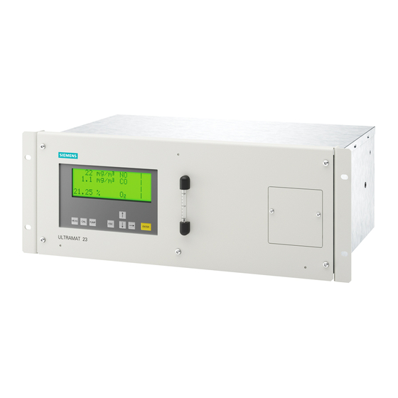
Siemens ULTRAMAT 23 Operating Instructions Manual
Gas analyzer for ir-absorbing gases and oxygen
Hide thumbs
Also See for ULTRAMAT 23:
- Manual (244 pages) ,
- Product information (22 pages) ,
- Compact operating instructions (37 pages)

Related Manuals for Siemens ULTRAMAT 23


Summary of Contents for Siemens ULTRAMAT 23
- Page 1 ULTRAMAT 23 Gas analyzer for IR-absorbing gases and oxygen 7MB2335, 7MB2337, 7MB2338 Operating Instructions 09/2009 • Continuous Gas Analysis...
- Page 3 ULTRAMAT 23 Gas Analyzer For IR-absorbing Gases And Oxygen 7MB2335, 7MB2337, 7MB2338 Operating Instructions Order No.: C79000-B5276-C216 Version 09/2009...
- Page 4 Messwesen” nur für den Export. ULTRAMAT, OXYMAT, SIPAN Toute communication ou reproduction de ce document, toute exploitation sont des marques déposées de Siemens. ou communication de son contenu sont interdites, sauf autorisation D’autres dénominations utilisées dans ce document peuvent également expresse.
-
Page 5: Table Of Contents
........... 4.3.3 System Setup with Several Analyzers in Parallel ....Operating Instructions ULTRAMAT 23 Gas Analyzer C79000-B5276-C216-03... - Page 6 ....5-35 5.10.1.3 Configuration: Inputs/Outputs/Pump: Binary/Sync Inputs ... 5-38 Operating Instructions ULTRAMAT 23 Gas Analyzer C79000-B5276-C216-03...
- Page 7 ........... 9-13 Operating Instructions ULTRAMAT 23 Gas Analyzer C79000-B5276-C216-03...
- Page 8 Operating Instructions ULTRAMAT 23 Gas Analyzer C79000-B5276-C216-03...
- Page 9 ......Conformity with European Guidelines ....Operating instructions ULTRAMAT 23 Gas Analyzer C79000-B5276-C216-03...
-
Page 10: Information For The User
Should you require further information, or should particular problems occur which are not handled in sufficient depth in this instructions, help can be requested through your local Siemens office or representative. Operating instructions ULTRAMAT 23 Gas Analyzer... -
Page 11: Notes On Using This Instructions
Notice is important information on the product itself, the handling of the product or the respective part of the instructions to which particular attention should be paid. Operating instructions ULTRAMAT 23 Gas Analyzer C79000-B5276-C216-03... -
Page 12: Approved Use
Technical Description (see also Chapter 3 of this instructions) and only in conjunction with other devices and components which have been recommended or approved of by Siemens. The product described in this instructions has been developed, manufactured, tested and documented taking into account the appropriate safety standards. -
Page 13: Qualified Personnel
All commitments on the part of Siemens are contained in the respective sales contract which also contains the complete and solely applicable warranty conditions. These warranty conditions in the contract are neither extended nor limited by the contents of this instructions. -
Page 14: Standards And Regulations
Conformity with European Guidelines symbol EMC guideline The ULTRAMAT 23 gas analyzer complies with the requirements of the EU guideline 89/336/EEC ”Electromagnetic compatibility”. Observation of this EU guideline has been checked according to DIN EN 61326-1 2006. -
Page 15: Installation Guidelines
........Operating instructions ULTRAMAT 23 gas analyzer... -
Page 16: Safety Information
Exposure to some chemicals may degrade the sealing properties of materials used in the following devices: - Relais on mainboard: W79052-K5001-C5; manufacturer: Axicom, part V23026-A1001-B20 - IR-Radiation Source: C79451-A3468-B205 or 206; manufacturer: Siemens AG Operating instructions ULTRAMAT 23 gas analyzer C79000-B5276-C216-03... -
Page 17: Assembly Instructions
The permissible ambient temperature must be observed during operation. The ULTRAMAT 23 must be placed on supporting rails if it is to be fitted in a cabinet or benchtop housing. Assembly only at the front is insufficient because the weight of the analyzer would place too great a load on the chassis. -
Page 18: Gas Connections And Internal Gas Paths
(e.g. when using analyzer cabinets or houses) such that it is guaranteed that only changes in atmospheric pressure are recorded. Gas connections Refer to the Technical Description (Chapter 3) in this Manual. and gas paths Operating instructions ULTRAMAT 23 gas analyzer C79000-B5276-C216-03... -
Page 19: Gas Conditioning
Installation Guidelines Gas Conditioning The sample gas must be sufficiently conditioned to prevent contamination of the parts through which it flows. The ULTRAMAT 23 is usually preceded by a gas sampling device with filter, a sample gas cooler, an analysis filter (1-2 μm) and an external gas suction pump (with sample gas lines >... -
Page 20: Electric Connection
70 °C. When positioning the analyzer, make sure that the power switch on the rear is accessible at all times. Check that the local mains voltage agrees with that specified on the rating plate on the analyzer. Operating instructions ULTRAMAT 23 gas analyzer C79000-B5276-C216-03... -
Page 21: Connection Of Signal Cables
The cables (apart from the mains cable) must be screened, and their screen must be screen connected at both ends to ground. The 24 V/1A power supply must be a power-limited safety extra-low voltage with safe electrical isolation (SELV). Operating instructions ULTRAMAT 23 gas analyzer C79000-B5276-C216-03... - Page 22 Installation Guidelines Operating instructions ULTRAMAT 23 gas analyzer C79000-B5276-C216-03...
-
Page 23: Technical Description
......... 3-15 Circuit diagrams (electric and gas connections) ....3-17 Operating instructions ULTRAMAT 23 gas analyzer C79000-G5276-C216-03... -
Page 24: 3.1 General
Application areas .1.1 • Optimization of small firing systems The ULTRAMAT 23 gas analyzer can measure up to 4 gas com- • Monitoring of exhaust gas concentration from firing systems ponents at once: A maximum of three infrared sensitive gases... -
Page 25: 3.2 Design
N ↑↓ → Keys for menu control; or air without CO increasing/decreasing numerical values Switch internal pump on and off; Scroll back in menu or pump flowrate adjustable via menu cancel an input Operating instructions ULTRAMAT 23 gas analyzer C79000-B5276-C216-03... - Page 26 SS, type No. 1.4571 Pipes SS, type No. 1.4571 Sample cell • Body Aluminium • Cell lining Aluminium • Stub SS, type No. 1.4571 • Window CaF2 • Adhesive E353 • O-ring FPM (Viton) Operating instructions ULTRAMAT 23 gas analyzer C79000-B5276-C216-03...
- Page 27 Technical Description ULTRAMAT 23 also available as bench-top unit: ● 2 handles on top cover ● 4 rubber feet for setting up ● No mounting frame 80-digit display Dust-tight and washable (4 lines/20 characters) membrane keypad Flowmeter in conjunction with...
- Page 28 N 2 ) with O without O Enclosure flushing Chopper compartment flushing ULTRAMAT 23, portable, in sheet-steel housing with internal sample gas pump, condensation trap with safety filter on front panel, optional oxygen measurement Operating instructions ULTRAMAT 23 gas analyzer C79000-B5276-C216-03...
- Page 29 Zero gas not used Enclosure flushing Atmospheric pressure sensor Chopper purge with O without O ULTRAMAT 23, 19“ unit with internal sample gas pump, optional oxygen measurement Gas inlet Gas outlet not used not used Enclosure flushing Atmospheric pressure sensor Chopper...
- Page 30 Atmospheric pressure sensor Chopper purge ULTRAMAT 23, 19“ unit without internal sample gas pump, with separate gas path for the second component or for the 2nd and 3rd components, optional oxygen measurement Gas inlet 1 Gas outlet 1 Gas inlet 2...
-
Page 31: 3.3 Function
6 Oxygen diffusion resistor for temperature membrane made compensation of FEP ULTRAMAT 23, mode of operation of oxygen measuring cell Sample gas Essential characteristics outlet • Practically maintenance-free as a result of AUTOCAL with am- bient air (or with N , devices without oxygen sensor);... -
Page 32: 3.4 Integration
Data bits The gas analyzers of series 6 (ULTRAMAT 6, Stop bit ULTRAMAT/OXYMAT 6, OXYMAT 6/61/64, FIDAMAT 6 and Start bit CALOMAT 6/62), as well as the ULTRAMAT 23 offer the following communications facilities: Parity None • RS 485 interface No echo mode •... - Page 33 There navigate to the ’Entry list’ tab and select ’Download’ as en- complex parameter structure of the analyzers, permitting opera- try type. tion to be carried out simply by clicking. Example of a PROFIBUS system structure Operating instructions ULTRAMAT 23 gas analyzer 3-11 C79000-B5276-C216-03...
- Page 34 ULTRAMAT/OXYMAT 6, OXYMAT 6, OXYMAT 61, FIDAMAT 6 a profile is a prerequisite for the uniform response of devices and CALOMAT 6), as well as the ULTRAMAT 23 are suitable for from different vendors, the so-called interoperability.The profile PROFIBUS when fitted with the optional plug-in card.
-
Page 35: 3.5 Technical Data
0 (1) to 24 hours Options Supplementary electronics with 8 additional binary inputs and relay outputs, e.g. for external auto- matic calibration and for PROFI- BUS PA or PROFIBUS DP Operating instructions ULTRAMAT 23 gas analyzer 3-13 C79000-B5276-C216-03... - Page 36 1% change in pressure Power supply < 0.1% of output signal span with a variation of ± 10% ± 2% of full-scale value with a fre- Power frequency quency variation of ± 5% 3-14 Operating instructions ULTRAMAT 23 gas analyzer C79000-B5276-C216-03...
-
Page 37: 3.6 Dimensional Drawings
3.6 Dimensional drawings 338.5 14.5 ∅ Gas connections: stubs 6 mm or ¼ Caution: always install on supporting rails when mounted in bench-top housing or in cabinet ULTRAMAT 23, 19“ unit, dimensions in mm Operating instructions ULTRAMAT 23 gas analyzer 3-15 C79000-B5276-C216-03... - Page 38 Technical Description ∅ Gas connections: stubs 6 mm ULTRAMAT 23, desktop unit, dimensions in mm 3-16 Operating instructions ULTRAMAT 23 gas analyzer C79000-B5276-C216-03...
-
Page 39: Circuit Diagrams (Electric And Gas Connections)
P 20 Pump On/Off Safety extra-low voltage (SELV) with save N (2, 20, 21) electrical isolation. Note: Cable and connectors must be shielded and connected to chassis potential. ULTRAMAT 23, pin assignment (standard) Operating instructions ULTRAMAT 23 gas analyzer 3-17 C79000-B5276-C216-03... - Page 40 Connector SUB-D 9M -X90 Connector SUB-D 9F -X90 optional PROFIBUS-PA PROFIBUS-DP DGND CNTR-N CNTR-P/direction control RxD/TxD-N (A) Pa-N(-) RxD/TxD-P (B) PA-P(+) VP /+ 5 V ULTRAMAT 23, pin assignment of the optional PROFIBUS interface board Operating instructions ULTRAMAT 23 gas analyzer C79000-B5276-C216-03 3-18...
- Page 41 Gas connections: stubs 6 mm or ¼" relay outputs (front gas inlet) When installing in a cabinet, mount only on support rails. ULTRAMAT 23 portable unit, in sheet-steel housing, gas and electrical connections Operating instructions ULTRAMAT 23 gas analyzer 3-19 C79000-B5276-C216-03...
- Page 42 19” rack unit 19” rack unit 19” rack unit housing with sample gas pump without sample gas pump with two separate gas paths or pipe version ULTRAMAT 23, designation of the different Operating instructions ULTRAMAT 23 gas analyzer C79000-B5276-C216-03 3-20...
-
Page 43: Start-Up
........... 4.3.3 System Setup with Several Analyzers in Parallel ....Operating instructions ULTRAMAT 23 gas analyzer C79000-B5276-C216-03... -
Page 44: Safety Information
Do not remove or replace lamps or fuses unless power has been disconnected or when a flammable or combustible atmosphere is present. Failure to observe these safety instructions may result in death, severe personal injuries and or substantial damage to property and environment. Operating instructions ULTRAMAT 23 gas analyzer C79000-B5276-C216-03... -
Page 45: Preparations For Start-Up
Start-up ATEX Zone 2 ULTRAMAT 23 Type 7MB2335, 7MB2337 and 7MB2338 must be installed in a suitable enclosure in accordance with EN 60079-15, taking into account the environmental conditions under which the equipment will be used. When the temperature under rated conditions exceeds 70 °C at the cable or conduit entry point, or 80 °C at the branching point of the... - Page 46 You can manually trigger an AUTOCAL during operation by pressing the CAL key. The ULTRAMAT 23 can also execute an AUTOCAL cyclically, i.e. at adjustable, regular intervals (see below). The duration of the AUTOCAL depends on various factors. It takes Duration approx.
- Page 47 (99 % value). The compensation of the temperature influence is stored in the Compensation of temperature EEPROM in the ULTRAMAT 23. Modifications can only be made in the factory. influence Noise suppression Any noise which may occur can be suppressed by adjusting various time constants (see Section 5.9).
- Page 48 Zero gas for AUTOCAL DC 24 V power supply SYNC ULTRAMAT 23 slave SYNC Digital input Fig. 4-1 Example with internal pump and solenoid valve switching Protective extra-low voltage with safe electrical isolation (SELV) Operating instructions ULTRAMAT 23 gas analyzer C79000-B5276-C216-03...
- Page 49 Set the AUTOCAL cycle time to ”0” to prevent a cyclic AUTOCAL from being triggered (see Section 5.8.4). Assign the function ”Sync.” to a relay (see Section 5.10.1.2). Assign the function ”AUTOCAL” to the digital input SYNC (see Section 5.10.1.3). Operating instructions ULTRAMAT 23 gas analyzer C79000-B5276-C216-03...
- Page 50 DC 24 V power Zero gas for supply AUTOCAL SYNC ULTRAMAT slave SYNC Digital input Fig. 4-2 Example without internal pump and solenoid valve switching Protective extra-low voltage with safe electrical isolation (SELV) Operating instructions ULTRAMAT 23 gas analyzer C79000-B5276-C216-03...
-
Page 51: Operation
... . . 5-22 5.8.2.2 Calibration: Calibrate O2 Sensor: O2 Zero Cal....5-23 Operating instructions ULTRAMAT 23 gas analyzer C79000-B5276-C216-03... - Page 52 ........... . 5-47 Operating instructions ULTRAMAT 23 gas analyzer C79000-B5276-C216-03...
-
Page 53: General
User prompting In the next sections, operation of the ULTRAMAT 23 is explained according to the following scheme: _____________________________________________________________________________ Example menu 1: Example menu 2: Example menu 3 Example text. -
Page 54: Display And Input Panel
Fault logged which is no longer present R: Remote control C: Function Control (analyzer uncoded, or access via RS485 serial interface, or AUTOCAL, or in approx. 30 min warm-up mode) P: Pump running U: Uncoded Operating instructions ULTRAMAT 23 gas analyzer C79000-B5276-C216-03... - Page 55 Operation User desktop The ULTRAMAT 23 has a menu-based user desktop. The menu structures can always be represented as follows: MAIN MENU → Submenu 1 → Submenu 2 → Submenu 3 → Submenu 4. Fig. Fig. 5-2 shows a diagram of the basic configuration of the user desktop.
- Page 56 Operation Key assignments Eight keys are available for operating the ULTRAMAT 23. These keys have the following meanings: Table 5-1 Input keys Designation Meaning Function MEAS Measure Measure; abort input operations; leave input mode (from any menu level); switch from input mode to measuring mode and code analyzer again (cf.
-
Page 57: Warm-Up Mode
Configuration Fig. 5-3 Warm-up mode, measuring mode and input mode Immediately following switching-on, the ULTRAMAT 23 tests the display elements. During this test, all elements light up simultaneously for approx. five seconds. The adjacent display subsequently appears with the remaining... -
Page 58: Measuring Mode
Analyzer status main menu which displays four menu items. You can use these to Calibration Parameters select the individual input functions of the ULTRAMAT 23: Configuration Analyzer status You can call submenus which provide information on the analyzer status, e.g. entries in the logbook, diagnostics data and factory data (see Fig. -
Page 59: Code Levels
5.5.1 Code Levels The ULTRAMAT 23 is provided with two code levels to protect against unauthorized or unintentional inputs. As soon as you call a protected function for the first time, you will be requested to enter the defined three-digit code number. -
Page 60: Key Operations Step-By-Step
Limit values Time constants Pump/LCD contrast Now select components 1 to 4 for which the subsequently set Choose component ranges are to apply. Up to four components can be present. : NO 5-10 Operating instructions ULTRAMAT 23 gas analyzer C79000-B5276-C216-03... - Page 61 : No, go to meas. Once you have carried out the above sequence on the analyzer, you are already acquainted with a number of important points for operation of the ULTRAMAT 23. 5-11 Operating instructions ULTRAMAT 23 gas analyzer C79000-B5276-C216-03...
-
Page 62: Using The Esc Key
Pump/LCD contrast Press the ESC key twice, you are back in measuring mode again. 403.8 vpm 1875 936.4 vpm 5-12 Operating instructions ULTRAMAT 23 gas analyzer C79000-B5276-C216-03... -
Page 63: Recoding The Analyzer
Following input of the code, inputs are possible until the analyzer is recoded. Notice In order to code the analyzer again when the input procedures have been finished (to protect against unauthorized and unintentional interventions), press the MEAS key in measuring mode. 5-13 Operating instructions ULTRAMAT 23 gas analyzer C79000-B5276-C216-03... - Page 64 Operation Fig. 5-4 Menu sequence for ”Analyzer status” 5-14 Operating instructions ULTRAMAT 23 gas analyzer C79000-B5276-C216-03...
-
Page 65: Analyzer Status: Status
The arrows lead by one menu item to the next lower menu/dialog level which is called by this menu item. 5.7.1 Analyzer Status: Status In this menu you can call the status messages of the ULTRAMAT 23 Logbook/faults via further menu items. Maintenance request... -
Page 66: Analyzer Status: Status: Maintenance Request
6.0 mV (maintenance request). 5714 Reading is the current voltage of O measuring cell Maint. req and Fault are the two minimum values which output a maintenance request or a fault message when fallen below. 5-16 Operating instructions ULTRAMAT 23 gas analyzer C79000-B5276-C216-03... -
Page 67: Analyzer Status: Diagnostic Values
Negative 20.93 % values are also displayed (live zero). The current measuring range 5721d is output on this display in the last two columns. 5-17 Operating instructions ULTRAMAT 23 gas analyzer C79000-B5276-C216-03... -
Page 68: Analyzer Status: Diagnostic Values: O2 Diagnostic Values
Bridge: The supply voltage to the measuring bridge. LCD temperature LCD temp. : 34.9°C The temperature which determines the display contrast. Refer to Section 5.9.4.2 for adjustment of the LCD contrast. 5724c 5-18 Operating instructions ULTRAMAT 23 gas analyzer C79000-B5276-C216-03... -
Page 69: Analyzer Status: Factory Settings Hardware
Factory settings are parameters which are already set on delivery and Firmware No.: which cannot be modified by the user, such as the software/firmware Software version: release version. The software release version can be read here. date 5-19 Operating instructions ULTRAMAT 23 gas analyzer C79000-B5276-C216-03... - Page 70 Correct with ENTER 5822 AUTOCAL Thermo-AUTOCAL: OFF Cycle time: XX hours Cycle time AUTOCAL Purge time Time left: XX.XX h 5841 Purge time XXXX seconds 5842 Fig. 5-5 Menu sequence for ”Calibration” 5-20 Operating instructions ULTRAMAT 23 gas analyzer C79000-B5276-C216-03...
-
Page 71: Calibration
Calibration Using this function it is possible to calibrate the IR channels of the ULTRAMAT 23 using one or more calibration gases, and to reset the sensitivity. In addition, you can calibrate the oxygen sensor and the pressure sensor and also define the AUTOCAL parameters. Fig. 5-5 shows the associated menu sequence (see Section 5.7 for description... -
Page 72: Calibration: Calibrate Ir Channels: Start With Range Mr 1/2
A check is carried out during this procedure to establish whether the sensor voltage is greater than 9 mV. If this is not the case, a fault message ”Sensor voltage too low”. 5-22 Operating instructions ULTRAMAT 23 gas analyzer C79000-B5276-C216-03... -
Page 73: Calibration: Calibrate O2 Sensor: O2 Zero Cal
In the first line of this dialog, you can re-enter the setpoint of the Set value: 1000 mbar pressure sensor. Measure a value e.g. using an accurate barometer, Reading: 1007 mbar Enter new set value and change the setpoint in the first line if necessary. 5-23 Operating instructions ULTRAMAT 23 gas analyzer C79000-B5276-C216-03... -
Page 74: Calibration: Autocal
60 to 300 s, otherwise 0 to 300 s. There are minimum purge times depending on the measured components, and shorter times should not be used. 80 seconds has been selected in our example. 5-24 Operating instructions ULTRAMAT 23 gas analyzer C79000-B5276-C216-03... - Page 75 : XX.X % 5941 Adjsut pump / flow Adjust LCD contrast Adjust LCD contrast Use -> to adjust ENTER: Save new val. ESC: Keep old val. 5942 Fig. 5-6 Menu sequence for ”Parameters” 5-25 Operating instructions ULTRAMAT 23 gas analyzer C79000-B5276-C216-03...
-
Page 76: Parameters
AR: The analyzer switches over automatically from one range to the other (AR = autorange). Refer to Section 5.9.1.3 for how to set the switch over criteria. 5-26 Operating instructions ULTRAMAT 23 gas analyzer C79000-B5276-C216-03... -
Page 77: Parameters: Measuring Ranges: Change Ranges
If your analyzer is working in the larger range (MR2), it switches over to the smaller range (MR1) when a value less than 360 mg/m is measured (= 90 % of 400 mg/m 5-27 Operating instructions ULTRAMAT 23 gas analyzer C79000-B5276-C216-03... -
Page 78: Parameters: Limit Values
(Alarm at conc.:): 592a High: with upward violation Low: with downward violation - - - - -: no signal; see Fig. 5-28 Operating instructions ULTRAMAT 23 gas analyzer C79000-B5276-C216-03... -
Page 79: Parameters: Time Constants
5.9.4 Parameters: Pump/LCD Contrast You can use this menu to select two dialogs via which the pump Adjust pump/flow capacity and the contrast of the LCD can be changed. Adjust LCD contrast 5-29 Operating instructions ULTRAMAT 23 gas analyzer C79000-B5276-C216-03... -
Page 80: Parameters: Pump/Lcd Contrast: Adjust Pump
Store the set contrast using the ENTER key Cancel the input using the ESC key. Notice Press the three keys ↑ , ↓ and → simultaneously to set an average contrast again. 5-30 Operating instructions ULTRAMAT 23 gas analyzer C79000-B5276-C216-03... - Page 81 Operation Fig. 5-9 Menu sequence for ”Configuration” 5-31 Operating instructions ULTRAMAT 23 gas analyzer C79000-B5276-C216-03...
- Page 82 Operation Fig. 5-10 Menu sequence for ”Configuration” (continued) 5-32 Operating instructions ULTRAMAT 23 gas analyzer C79000-B5276-C216-03...
-
Page 83: 5.10 Configuration
4 mA. Set value : Range 4 / 20 mA Meas.value neg. OFF The following tables represent the correlation between analog current outputs and measuring range limits. 51011a 5-33 Operating instructions ULTRAMAT 23 gas analyzer C79000-B5276-C216-03... - Page 84 Hold: The value measured directly prior to commencement is output unchanged. This also applies to the limits which are output (see section 5.9.2) Actual: The measured value is continuously updated. Zero: see following table: 5-34 Operating instructions ULTRAMAT 23 gas analyzer C79000-B5276-C216-03...
- Page 85 1) If measuring range 2 is set to the maximum possible value, the limiting value of range 2 ... 20 mA is at 20.9 mA and of range 4 ... 20 mA at 20.8 mA. 5-35 Operating instructions ULTRAMAT 23 gas analyzer C79000-B5276-C216-03...
- Page 86 The upper and lower limits can be defined as events for triggering Limit 2: Relay 2 relays. Select the desired relay number in the second and third lines. 51012a This function is specific to the component. 5-36 Operating instructions ULTRAMAT 23 gas analyzer C79000-B5276-C216-03...
- Page 87 Span gas: The calibration gas supply (assigned to relay 7 in Fig.; see Section 5.10.3.2) Sync: The synchronization of an AUTOCAL with other devices within a system (assigned to relay 8 in Fig.; see Section 4.3.3). 5-37 Operating instructions ULTRAMAT 23 gas analyzer C79000-B5276-C216-03...
-
Page 88: Configuration: Inputs/Outputs/Pump: Binary/Sync Inputs
Using a submenu for the 8 inputs, you can switch over 7 different messages for faults/maintenance requests or switch over 4 different messages for function check or switch over measuring ranges or delete the logbook. 5-38 Operating instructions ULTRAMAT 23 gas analyzer C79000-B5276-C216-03... - Page 89 In the first two lines of this dialog, you can change the codes of the two Code 1: 111 code levels 1 and 2 (see also Section 5.5.1). The factory settings are: Code 2: 222 Language: English Code 1: 111; 51021 Code 2: 222. 5-39 Operating instructions ULTRAMAT 23 gas analyzer C79000-B5276-C216-03...
-
Page 90: Configuration: Special Functions: Autocal Drift
You can also reduce the number of code levels by assigning the same code to both levels. The new values are saved when you subsequently switch off the ULTRAMAT 23; you should therefore make a note of the changed code numbers and keep this at a safe place. -
Page 91: Configuration: Special Functions: Elan/Profibus
For further details on the ELAN, please refer to the ELAN interface description (C79000-B5274-C176 German/English) ELAN ext. Interfer. Parameterization with two analyzers is used as an example. Analyzer 1 delivers measured values, analyzer 2 uses these values for a correction calculation. 5-41 Operating instructions ULTRAMAT 23 gas analyzer C79000-B5276-C216-03... - Page 92 -2.4000e-1 = corr. interference of +6 vpm CO for 25 % CO2, i.e. -6/25 Neither analyzer is capable of measurements during the AUTOCAL process -> Evaluate function check (see Section 5.10.1.2)! Fig. 5-1 ELAN external interferences 5-42 Operating instructions ULTRAMAT 23 gas analyzer C79000-B5276-C216-03...
- Page 93 Example: A constant interference of +10 ppm is detected. You enter -10 ppm as correction value. Thus the measured value will be modified from +10 ppm to 0 ppm. 5-43 Operating instructions ULTRAMAT 23 gas analyzer C79000-B5276-C216-03...
-
Page 94: Configuration: Special Functions: Fact. Data/Res/Units
You can use this test to check the selected components of the Test:Displ/Keys/Flow analyzer. These include the front panel keys, the LCD, inputs and Inputs/Outputs Chopper/IR source outputs and a number of internal analyzer components. RAM monitor 5103 5-44 Operating instructions ULTRAMAT 23 gas analyzer C79000-B5276-C216-03... -
Page 95: Configuration: Tests: Display/Keys/Flow
The electric inputs and outputs of the analyzer are tested here. You Test analog outputs require the following equipment to carry out these tests: Test of relays Test ext. sol. valve Test of inputs Ammeter, 51032 Ohmmeter, Power supply and/or Test plugs. 5-45 Operating instructions ULTRAMAT 23 gas analyzer C79000-B5276-C216-03... - Page 96 ”Pump ON/OFF”, ”CAL” or ”SYNC”. The result is displayed in the fourth line (no input in this case). 51032d The external binary inputs of analyzers with option module can be tested in the menu ”Binary inputs” (see Section 5.10.1.3). 5-46 Operating instructions ULTRAMAT 23 gas analyzer C79000-B5276-C216-03...
-
Page 97: Configuration: Tests: Chopper/Ir Source
Please enter special code: 0000 analyzer, access to these factory settings is only possible by servicing engineers using a special access code. 5104 5-47 Operating instructions ULTRAMAT 23 gas analyzer C79000-B5276-C216-03... -
Page 98: Other Inputs
ESC key. In addition to the CAL key, an AUTOCAL can also be triggered via the binary input. The binary input has priority ober the key. 5-48 Operating instructions ULTRAMAT 23 gas analyzer C79000-B5276-C216-03... -
Page 99: Maintenance
......... Operating instructions ULTRAMAT 23 gas analyzer... -
Page 100: Messages
Maintenance Messages The ULTRAMAT 23 can detect and display various fault statuses. The fault statuses are divided into maintenance requests and fault messages. 6.1.1 Maintenance Requests Maintenance requests are references to certain changes in the analyzer which - at the time they are made - have no influence on the analyzer measurements. -
Page 101: Fault Messages
Temp. of analyzer beyond Ambient temperature too high or Provide sufficient ventilation or air tolerance too low conditioning. Temperature sensor of a detector faulty Pressure of amb. air beyond Pressure sensor faulty tolerance Operating instructions ULTRAMAT 23 gas analyzer C79000-B5276-C216-03... - Page 102 OK The cable of the detector has no Check that the plug is correctly contact connected to the detector (the plug must latch in twice). Cable of detector faulty Operating instructions ULTRAMAT 23 gas analyzer C79000-B5276-C216-03...
- Page 103 Sensitivity of O sensor too low sensor faulty or old Replace the O sensor as described in Section 6.2.1 . Overflow of AD converter Electronics faulty External fault Signaling of an external fault Operating instructions ULTRAMAT 23 gas analyzer C79000-B5276-C216-03...
-
Page 104: Maintenance Work
Comprehensive measures must therefore be made to protect them wherever they are manufactured, tested, transported and installed. Warning Before opening the analyzer, disconnect all poles from the mains sup• ply. Operating instructions ULTRAMAT 23 gas analyzer C79000-B5276-C216-03... -
Page 105: Replacement Of O Sensor
Reconnect the plug. Enter the date of installation in the menu item ”O cal. after install” as described in Section 5.8.2.1. Calibrate the O zero as described in Section 5.8.2.2. Operating instructions ULTRAMAT 23 gas analyzer C79000-B5276-C216-03... -
Page 106: Replacement Of Fuse
Find the contaminated filter according to its type (see Section 7, spare parts list, page 7-18, pos. 14 and 15). Remove the hoses from the filter. Replace the contaminated filter. The filter must be disposed of as residual waste! Operating instructions ULTRAMAT 23 gas analyzer C79000-B5276-C216-03... -
Page 107: Emptying The Condensation Trap
Push the condensation trap on again from below. Maintenance of Gas Path Depending on the corrosivity of the sample gas, check the state of the gas path at regular intervals. Servicing may be necessary. Operating instructions ULTRAMAT 23 gas analyzer C79000-B5276-C216-03... -
Page 108: Cleaning The Analyzer
Maintenance Cleaning the Analyzer Wipe the outer surfaces of the analyzer using a soft cloth dampened with a solution of mild cleaning agent. 6-10 Operating instructions ULTRAMAT 23 gas analyzer C79000-B5276-C216-03... - Page 109 ..... Measures for Scrapping the Analyzer ......Operating instructions ULTRAMAT 23 gas analyzer C79000-B5276-C216-03...
- Page 110 Shut-down It may be necessary to shut down the ULTRAMAT 23 for the following reasons: Repair New location of use Scrapping Measures for Repair or Changing of Location If the ULTRAMAT 23 is shut down for repair or for changing the location of use, proceed as follows: 19”...
- Page 111 Disposal of the The analyzer must be disposed of as electronic waste with the code analyzer number 160213 ”Equipment containing dangerous components”. It must therefore be disposed of in a correct and environmentally safe manner. Operating instructions ULTRAMAT 23 gas analyzer C79000-B5276-C216-03...
- Page 112 Shut-down Operating instructions ULTRAMAT 23 gas analyzer C79000-B5276-C216-03...
- Page 113 Spare Parts List Operating instructions ULTRAMAT 23 gas analyzer C79000-B5276-C216-03...
- Page 114 éditions suivantes. Nous vous remercions pour toutes propositions visant à améliorer la qualité de ce document. E Copyright Siemens AG - 2005, 2008, 2009 - All Rights reserved Technical data subject to change Technische Änderungen vorbehalten Sous réserve de modifications techniques...
- Page 115 4. Gerätename, MLFB- und Fab.-Nr. des Gasanalysengerätes, zu dem das Ersatzteil gehört. Bestelladresse: Siemens AG CSC (Centre Service Client) 1, chemin de la Sandlach F-67506 Haguenau/Frankreich Tel.: +33 3 6906 5555 Fax: +33 3 6906 6688 Operating instructions ULTRAMAT 23 Gas analyzer C79000-B5276-C216-03...
- Page 116 ULTRAMAT 23 type 7MB2337-2AF10-3PH1 Serial No. J2-111 Bestellbeispiel: 1 Sauerstoffsensor C79451-A3458-B55 für ULTRAMAT 23 Typ 7MB2337-2AF10-3PH0 Fab.-Nr. J2-111 Exemple de commande: 1 capteur d’oxygène C79451-A3458-B55 pour ULTRAMAT 23 type 7MB2337-2AF10-3PH2 Nº de fab. J2-111 Operating instructions ULTRAMAT 23 Gas analyzer C79000-B5276-C216-03...
- Page 117 Le remplacement de pièces, en particulier au bloc d’analyse ne peut être effectué qu’au CSC de Haguenau ou par du personnel qualifié. Une intervention inappropriée peut réduire la précicion de mesure ou entraver le bon fonctionnement de l’appareil. Operating instructions ULTRAMAT 23 Gas analyzer C79000-B5276-C216-03...
- Page 118 Spare parts list Note of the measuring accuracy To maintain the measuring accuracy of the ULTRAMAT 23 it may be necessary to perform temperature compensation after changing parts. The appropriate parts are marked by *). This is particularly the case when brief temperature fluctuations >5 °C occur at the erection site.
- Page 119 Spare parts list Gray: Analyzer section Gris:. Partie analyse Grau: Analysierteil Weiß: Elektronikteil White: Electronics section Blanc: Partie électronique Operating instructions ULTRAMAT 23 Gas analyzer C79000-B5276-C216-03...
- Page 120 Variante rack 19” avec des circuits de gaz séparés 19-Zoll-Ausführung in Rohr 19” rack version, pipe variante rack 19”, tube Bezeichnungen s. Seite 8-10 Designations see page 8-10 Désignations voir page 8-10 Operating instructions ULTRAMAT 23 Gas analyzer C79000-B5276-C216-03...
- Page 121 GASWEG/HOSING SYSTEM FOR GAS/CIRCUIT DE GAZ 19-Zoll-Ausführung, Rohr mit getrennten Gaswegen 19” rack version, pipe with separate gas paths Variante rack 19”, tube avec des circuits de gaz séparés Tischausführung Bench-top version Variante portable Operating instructions ULTRAMAT 23 Gas analyzer C79000-B5276-C216-03...
- Page 122 Filtre de sécurité pour gaz de à l’ìntérieur mesure Sicherheitsfilter Nullgas/ A5E00059149 innenliegend Chopperraumbespülung inside Safety filter zero gas/ à l’ìntérieur chopper purge Filtre de sécurité pour gaz de zéro/ balayage de l’obturateur Operating instructions ULTRAMAT 23 Gas analyzer 8-10 C79000-B5276-C216-03...
- Page 123 Spare parts list 19-Zoll-Ausführung 19” rack version Variante rack 19” 12, 12.1 Tischausführung Bench-top version Variante portable Bezeichnungen s. Seite 8-12 Designations see page 8-12 Désignations voir page 8-12 Operating instructions ULTRAMAT 23 Gas analyzer 8-11 C79000-B5276-C216-03...
- Page 124 12.1 Filter C79451- - A3008- - B60 im Kondensatbehälter, Packungseinheit: 3 Stück Filter in the condensation trap, Filtre package size: 3 units dans le pot de condensation, Paquet de 3 pcs. Operating instructions ULTRAMAT 23 Gas analyzer 8-12 C79000-B5276-C216-03...
- Page 125 Spare parts list ELEKTRONIK/ELECTRONICS/ELECTRONIQUE 5.1 / 5.2 19-Zoll-Ausführung 19” rack version Variante rack 19” 5.1 / 5.2 Tischausführung Bench-top version Variante portable Bezeichnungen s. Seite 8-14 Designations see page 8-14 Désignations voir page 8-14 Operating instructions ULTRAMAT 23 Gas analyzer 8-13 C79000-B5276-C216-03...
- Page 126 W79054- - L1011- - T125 100 V/120 V; T 1,25/250 V Fuse s. Aufschrift Geräterückseite/see rear of Fusible device/voir au dos de l’appareil Netzschalter W75050- - T1201- - U101 Power switch Interrupteur de mise sous tension Operating instructions ULTRAMAT 23 Gas analyzer 8-14 C79000-B5276-C216-03...
- Page 127 PUMPE/PUMP/POMPE Dichtung Gasket Joint d’étanchéité 8.1 / 8.2 Ventilplättchen Valve reed Lame de soupape Membran Diaphragm Membrane 3.1/2 2.1 (2) Bezeichnungen s. Seite 8-16 Designations see page 8-16 Désignations voir page 8-16 Operating instructions ULTRAMAT 23 Gas analyzer 8-15 C79000-B5276-C216-03...
- Page 128 Des travaux particuliers comme p. ex. la compensation de température, le réglage de base électrique etc., ne pouvant être exécutés que par du personnel qualifié sont à effectuer après un remplacement de pièces. Operating instructions ULTRAMAT 23 Gas analyzer 8-16 C79000-B5276-C216-03...
- Page 129 Analysierteil/Analyzer section/Partie analytique - Übersicht/summary/sommaire 8-17...
- Page 130 Spare parts list ANALYSIERTEIL/ANALYZER SECTION/PARTIE ANALYSE Analysierteil 7MB2335- Analyzer Section 7MB2335- Partie analyse 7MB2335- Bezeichnungen s. Seiten 8-19, 8-20 Designations see pages 8-19, 8-20 Désignations voir pages 8-19, 8-20 Operating instructions ULTRAMAT 23 Gas analyzer 8-18 C79000-B5276-C216-03...
- Page 131 , étendue min. < 2 % Gasfilter C79451- - A3468- - B543 für C Gas filter for C Filtre de gaz pour C *), **) siehe Folgeseite, see following page, voir page suivante 8-19 Operating instructions ULTRAMAT 23 Gas analyzer C79000-B5276-C216-03...
- Page 132 électrique etc., ne pouvant être exécutés que par du personnel qualifié sont à effectuer après un remplacement de pièces. Bitte nach Austausch die Wasserdampfquerempfindlichkeiten überprüfen. Following replacement, please check the water vapor interference. Après le remplacement, veuillez contrôler l’influence de la vapeur d’eau. Operating instructions ULTRAMAT 23 Gas analyzer 8-20 C79000-B5276-C216-03...
- Page 133 Spare parts list 8-21 Operating instructions ULTRAMAT 23 Gas analyzer C79000-B5276-C216-03...
- Page 134 Spare parts list ANALYSIERTEIL/ANALYZER SECTION/PARTIE ANALYSE Analysierteil 7MB2337- Analyzer Section 7MB2337- Partie analyse 7MB2337- Bezeichnungen s. Seite 8-23 Designations see page 8-23 Désignations voir page 8-23 Operating instructions ULTRAMAT 23 Gas analyzer 8-22 C79000-B5276-C216-03...
- Page 135 C79451- - A3468- - B543 für C O 500/5000 vpm Gas filter for C O 500/5000 vpm Filtre de gaz pour C O 500/5000 vpm *), **) siehe Folgeseite, see following page, voir page suivante 8-23 Operating instructions ULTRAMAT 23 Gas analyzer C79000-B5276-C216-03...
- Page 136 électrique etc., ne pouvant être exécutés que par du personnel qualifié sont à effectuer après un remplacement de pièces. Bitte nach Austausch die Wasserdampfquerempfindlichkeiten überprüfen. Following replacement, please check the water vapor interference. Après le remplacement, veuillez contrôler l’influence de la vapeur d’eau. Operating instructions ULTRAMAT 23 Gas analyzer 8-24 C79000-B5276-C216-03...
- Page 137 Spare parts list 8-25 Operating instructions ULTRAMAT 23 Gas analyzer C79000-B5276-C216-03...
- Page 138 Partie analyse 7MB2338-.AA..-, -.AK..-, -.AB..-, -.AC..- partie 1: configuration pour CO/NO dritte Komponente siehe S.8-33 third component see p. 8-33 troisième constituant voir p. 8-33 Bezeichnungen s. Seite 8-27 Designations see page 8-27 Désignations voir page 8-27 Operating instructions ULTRAMAT 23 Gas analyzer 8-26 C79000-B5276-C216-03...
- Page 139 électrique etc., ne pouvant être exécutés que par du personnel qualifié sont à effectuer après un remplacement de pièces. Bitte nach Austausch die Wasserdampfquerempfindlichkeiten überprüfen. Following replacement, please check the water vapor interference. Après le remplacement, veuillez contrôler l’influence de la vapeur d’eau. 8-27 Operating instructions ULTRAMAT 23 Gas analyzer C79000-B5276-C216-03...
- Page 140 1: configuration pour CO/NO dritte Komponente siehe Seite 8-33 third component see page 8-33 troisième constituant voir page 8-33 5.2.1 5.2.1 Bezeichnungen s. Seite 8-29 Designations see page 8-29 Désignations voir page 8-29 Operating instructions ULTRAMAT 23 Gas analyzer 8-28 C79000-B5276-C216-03...
- Page 141 électrique etc., ne pouvant être exécutés que par du personnel qualifié sont à effectuer après un remplacement de pièces. Bitte nach Austausch die Wasserdampfquerempfindlichkeiten überprüfen. Following replacement, please check the water vapor interference. Après le remplacement, veuillez contrôler l’influence de la vapeur d’eau. 8-29 Operating instructions ULTRAMAT 23 Gas analyzer C79000-B5276-C216-03...
- Page 142 Analyzer Section 7MB2338-.DC..- Partie analyse 7MB2338-.DC.. dritte Komponente siehe Seite 8-33 third component see page 8-33 troisième constituant voir page 8-33 Bezeichnungen s. Seite 8-31 Designations see page 8-31 Désignations voir page 8-31 Operating instructions ULTRAMAT 23 Gas analyzer 8-30 C79000-B5276-C216-03...
- Page 143 Des travaux particuliers comme p. ex. la compensation de température, le réglage de base électrique etc., ne pouvant être exécutés que par du personnel qualifié sont à effectuer après un remplacement de pièces. 8-31 Operating instructions ULTRAMAT 23 Gas analyzer C79000-B5276-C216-03...
- Page 144 1: configuration pour CO/CO dritte Komponente siehe Seite 8-33 third component see page 8-33 troisième constituant voir page 8-33 Bezeichnungen s. Seite 8-33 Designations see page 8-33 Désignations voir page 8-33 Operating instructions ULTRAMAT 23 Gas analyzer 8-32 C79000-B5276-C216-03...
- Page 145 Des travaux particuliers comme p. ex. la compensation de température, le réglage de base électrique etc., ne pouvant être exécutés que par du personnel qualifié sont à effectuer après un remplacement de pièces. 8-33 Operating instructions ULTRAMAT 23 Gas analyzer C79000-B5276-C216-03...
- Page 146 Komponente siehe S. 8-33 third component see p. 8-33 troisième constituant voir p. 8-33 nur 7MB2338-BB only 7MB2338-BB seulement 7MB2338-BB Bezeichnungen s. Seite 8-35 Designations see page 8-35 Désignations voir page 8-35 Operating instructions ULTRAMAT 23 Gas analyzer 8-34 C79000-B5276-C216-03...
- Page 147 Des travaux particuliers comme p. ex. la compensation de température, le réglage de base électrique etc., ne pouvant être exécutés que par du personnel qualifié sont à effectuer après un remplacement de pièces. 8-35 Operating instructions ULTRAMAT 23 Gas analyzer C79000-B5276-C216-03...
- Page 148 1: configuration pour CO dritte Komponente siehe S. 8-33 third component see p. 8-33 troisième constituant voir p. 8-33 Bezeichnungen s. Seite 8-37 Designations see page 8-37 Désignations voir page 8-37 Operating instructions ULTRAMAT 23 Gas analyzer 8-36 C79000-B5276-C216-03...
- Page 149 Filtre de gaz pour CO 9 *) Empfängerkammer C79451- - A3468- - B525 für CO Detector for CO Cellule de détection pour CO s. Fußnote Seite 7-37 see footnote page 7-37 voir page 7-37 8-37 Operating instructions ULTRAMAT 23 Gas analyzer C79000-B5276-C216-03...
- Page 150 Parties analyse 7MB2338-..0-. partie 2: troisième constituant Graue Bauteile: Teil 1 (Beispiel) Gray parts: part 1 (example) Pièces grises: partie 1 (exemple) Bezeichnungen s. Seiten 8-39/8-40 Designations see pages 8-39/8-40 Désignations voir pages 8-39/8-40 Operating instructions ULTRAMAT 23 Gas analyzer 8-38 C79000-B5276-C216-03...
- Page 151 *) siehe Folgeseite, see following page, voir page suivante Bitte nach Austausch die Wasserdampfquerempfindlichkeiten überprüfen. Following replacement, please check the water vapor interference. Après le remplacement, veuillez contrôler l’influence de la vapeur d’eau. 8-39 Operating instructions ULTRAMAT 23 Gas analyzer C79000-B5276-C216-03...
- Page 152 Des travaux particuliers comme p. ex. la compensation de température, le réglage de base électrique etc., ne pouvant être exécutés que par du personnel qualifié sont à effectuer après un remplacement de pièces. Operating instructions ULTRAMAT 23 Gas analyzer 8-40 C79000-B5276-C216-03...
-
Page 153: Appendix
........... 9-13 Operating instructions ULTRAMAT 23 gas analyzer C79000-B5276-C216-03... -
Page 154: Returned Deliveries
To enable fast detection and elimination of faults, please return the analyzers to the following address: - SIEMENS CSC (Centre Service Client) Tel.: +33 3 6906 5555 Fax: +33 3 6906 6688 1, chemin de la Sandlach F-67506 Haguenau Operating instructions ULTRAMAT 23 gas analyzer C79000-B5276-C216-03... - Page 155 Operating temperature Operating pressure Composition of sample gas Duration of use/ date put into service Repair report RH No.: Incoming date: Outgoing date: Technician: Do not fill in this block; for internal use Operating instructions ULTRAMAT 23 gas analyzer C79000-B5276-C216-03...
- Page 156 Appendix Your comments please Operating instructions ULTRAMAT 23 gas analyzer C79000-B5276-C216-03...
- Page 157 To avoid danger to the life or health of users or service engineers, and to avoid damage to property, certain sections of text in this Manual are identified by warning symbols (pictograms). General indication of danger It is essential to observe the operating instructions Operating instructions ULTRAMAT 23 gas analyzer C79000-B5276-C216-03...
- Page 158 Error correction in display ”O Check time constant cal after install date” (see Section 5.8.2.1) In dialog ”Parameters: Time constants” T90 instead of Tau (T63) (see Section 5.9.3) Company name ”SIEMENS” removed Internal corrections Operating instructions ULTRAMAT 23 gas analyzer C79000-B5276-C216-03...
- Page 159 Display of current measuring ranges in ”Analyzer status: Diagnostic values: IR diagnostic values: Not corrected conc.” (see Section 5.7.2.1) 2.01_ 3/98 Error correction: texts in menu ”O2 zero calibration” in English, French, Spanish, Italian Operating instructions ULTRAMAT 23 gas analyzer C79000-B5276-C216-03...
- Page 160 Check ELAN parameters completed 2.04_ 11/98 Error correction: sporadic measured-value spikes with ambient temperatures > 40 ˚C. 2.05_ 3/99 Error correction: display of parameters following acknowledgment of ”Accept modifications” by NO not always updated. Operating instructions ULTRAMAT 23 gas analyzer C79000-B5276-C216-03...
- Page 161 ”Load factory data”. versions <= 2.05. The current status is now always displayed in the menu ”IR source ON/OFF”. Pressure sensor can measure up to 600 mbar without error message (previously 700 mbar). Operating instructions ULTRAMAT 23 gas analyzer C79000-B5276-C216-03...
- Page 162 Extension in menu ”Range calibration” Extension of factory settings 2.14_ 02/06 Extension of communication via RS485/ELAN Extension for PROFIBUS menu: error correction Optimization of function ”Correction of cross- interference” 9-10 Operating instructions ULTRAMAT 23 gas analyzer C79000-B5276-C216-03...
- Page 163 Appendix Certificates TÜV Test certificate BB-EG1 - KAR Gr01 X for measurement of flammable gases Operating instructions ULTRAMAT 23 gas analyzer 9-11 C79000-B5276-C216-03...
- Page 164 Appendix 9-12 Operating instructions ULTRAMAT 23 gas analyzer C79000-B5276-C216-03...
- Page 165 : +5°C ... +45°C EN 61000-6-2, EN 61000-6-4 (replaces EN 50081-2) ATEX Zone 2 EN 60079-15 : 2005, EN 60079-0 : 2006 II 3 G Ex nA II T4 KEMA 09 ATEX 0027X Operating instructions ULTRAMAT 23 gas analyzer 9-13 C79000-B5276-C216-03...
- Page 166 Appendix 9-14 Operating instructions ULTRAMAT 23 gas analyzer C79000-B5276-C216-03...
- Page 168 Siemens AG Subject to change without prior notice C79000B5276C216 Industry Automation (IA) C79000-B5276-C216-03 Sensors and Communication © Siemens AG 2009 Process Analytics 76181 KARLSRUHE C79000B5276C216 GERMANY www.siemens.com/processautomation 4 019169 141222...