Table of Contents
Advertisement
Advertisement
Table of Contents
Troubleshooting

Related Manuals for Siemens RAPIDLAB 248


Summary of Contents for Siemens RAPIDLAB 248
- Page 1 Operator’s Manual 248 91 001N Rev. T, 2008-04...
- Page 2 No part of this manual or the products it describes may be reproduced by any means or in any form without prior consent in writing from Siemens Healthcare Diagnostics Inc. The 248 pH/Blood Gas Analyzer is for In Vitro Diagnostic Use.
-
Page 3: Intended Use
There are no user replaceable parts within the instrument. Do not remove the rear cover from the 248. Siemens Healthcare Diagnostics and its authorized Distributors and Agents consider themselves responsible for the effects of safety, reliability and performance of the 248 only if: •... -
Page 4: Conventions Used In This Manual
248 Operator’s Manual Conventions Used in this Manual This manual uses the following text and symbol conventions. Convention Description Bold type within text indicates either: B o l d A screen name For example, if the word ‘Ready’ appears as ‘Ready’, this indicates that ‘Ready’... - Page 5 248 Operator’s Manual Understanding the Symbols Symbol Description Advises you to consult the instructions for use to obtain safety related information Indicates that the analyzer is classed as IEC Type B equipment (Class 1 equipment providing an adequate degree of protection against electric shocks particularly regarding allowable leakage currents and reliability of the protective earth connection) Indicates that the system is listed by Underwriters Laboratories as meeting...
- Page 6 248 Operator’s Manual Understanding the Symbols Symbol Description Batch code Serial Number Use by Control Indicates maximum fill level Do not re-use Do not stack Do not use if package is damaged Keep this way up Please recycle this packaging Printed on recycled materials Indicates compliance with Green Dot packaging standards Indicates compliance with RESY packaging standards...
-
Page 7: Table Of Contents
Contents Page Intended Use Conventions Used in this Manual Understanding the Symbols Understanding the System 248 pH/Blood Gas Analyzer Overview The Front Panel The Rear Panel The 248 Software Setup Options Sample Information Reagents 1-10 Waste Disposal 1-11 Calibration 1-12 1-13 Operating the System Ready Screen... - Page 8 248 Operator’s Manual Contents Maintaining the System Daily Maintenance Weekly Maintenance Quarterly Maintenance Maintenance Schedule Six-Monthly Maintenance Emptying the Waste Bottle Changing the Reagents Deproteinizing the Sensors Conditioning the Sensors Using the Disinfect Routine Stopping the 248 System Using the Prime Routine Checking the Gas Pressure and Changing the Cylinders 3-10 Checking the Gas Flow Rate...
- Page 9 Contents Contents Troubleshooting the System Calibration Failures Calibration or Slope Drift Calibration or Slope No Endpoint Calibration or Slope Outside Range Fluidics Failure, Insufficient 7.3/6.8/Wash Suspect Results Sample Not Detected or Sampling Fault Printer Problems Hydraulic Problems Heater Problems 4-10 Using the Troubleshooting Routines 4-10 Measurement Block Routine...
- Page 10 viii 248 Operator’s Manual Contents Configuring the System Adjusting Correlation System Setup Changing Date and Time Setting the Maintenance Prompts Selecting Parameters Changing Beeper Option Changing Communication Options Setting Security Printing Setup Report Service Setup Entering System Information Changing Language Service and Supplies Ordering Information Spares...
-
Page 11: Understanding The System
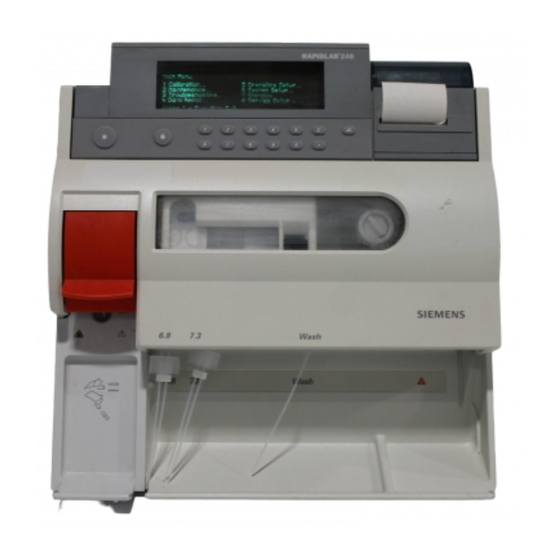
Page 1-1 1 Understanding the System 248 pH/Blood Gas Analyzer Overview Figure 1-1. Overview of 248 Analyzer Front Cover (raised) Printer Paper Paper Advance Control Controls Measurement Block Cover Sensors Measurement Pre-heater Block Catch and Tensioner Probe Lever Reagent Pump Tubing Probe Sleeve Sample Pump Tubing... -
Page 12: The Rear Panel
Page 1-2 248 Operator’s Manual The Rear Panel Figure 1-3. The Rear Panel Memory Card Slot Power Connector, Cal Gas Slope Gas Voltage Selector Connector Connector and Fuses Tubing Tubing These symbols appear on the rear of the instrument. Symbol Description Port 1 Data Port 1, 9-way D-line... - Page 13 Understanding the System Page 1-3 The Rear Panel Symbol Description Authorized Representative Serial Number Alerts you to important information about the fuses Indicates that the system is listed by Underwriters Laboratories as meeting U.S. and Canadian requirements for safety Indicates that the system meets the requirements of the European Union Indicates that the analyzer is classed as IEC Type B equipment (Class 1 equipment providing an adequate degree of protection against electric shocks particularly regarding allowable leakage currents and reliability of...
-
Page 14: The 248 Software
Page 1-4 248 Operator’s Manual The 248 Software The 248 is very easy to use, and the display leads you through the necessary steps to analyze samples, or to use any of the other functions. The 248 will normally display the Ready screen. (Full details of how to measure samples are in Section 2, Operating the System.) Ready 10:55:12... - Page 15 Understanding the System Page 1-5 Choosing Options The selected menu (Calibration) is highlighted briefly, confirming the keypress. The display shows the Calibration menu. Main Menu → Calibration 1 Full 1 Point 5 pH 1 Point 2 Full 2 Point 6 pH 2 Point 3 Gas 1 Point 7 Barometer 4 Gas 2 Point...
- Page 16 Page 1-6 248 Operator’s Manual Entering Data If you choose an option where you can enter data, the area (or field) for the data is highlighted. To see an example of data entry fields: From Ready press # for menu, 6 to select System Setup and 2 to select Maintenance Prompt.
-
Page 17: Setup Options
Understanding the System Page 1-7 Setup Options You can configure the 248 by choosing units of measurement, setting reference ranges and so on. This is covered in Section 5, Configuring the System. Section 5 also gives recommended settings where applicable. You can, of course, use the 248 using the default (factory set) options and values. - Page 18 Page 1-8 248 Operator’s Manual System Setup Date/Time Maintenance Prompt empty waste every day deproteinize/condition every 7 days Parameters measured pH, pCO and pO selected calculated none selected Beeper beeper Communications Port 1 CMSI Port 2 CMSI Security menu password not set Service Setup System Information...
-
Page 19: Sample Information
Capillary Tubes Capillary blood should be collected using Siemens capillary tubes. The minimum sample volume from a capillary is 60 μL. The capillary tube should be completely filled and the ends securely capped. The samples must be mixed thoroughly. -
Page 20: Reagents
Wear safety glasses, gloves and a laboratory coat when WARNING handling the reagents. The reagents described in this section are for in vitro diagnostic use only. Siemens cannot guarantee the performance of the system in any of the following situations: • Reagents other than those recommended are used. -
Page 21: Waste Disposal
Understanding the System Page 1-11 Active Ingredients Material Safety Data Sheets for the 248 reagents are supplied by your local distributor. Intended Use 7.382 buffer provides the calibration point for 1 and 2 point pH calibrations. 7.382 buffer is buffered to a pH of 7.382 at 37°C and is NIST traceable. -
Page 22: Calibration
Page 1-12 248 Operator’s Manual Calibration Gases Two gas standards are used to calibrate the pCO and pO sensors. Cal Gas provides the calibration point for 1 and 2 point pCO calibrations. Cal Gas contains 5.00 ± 0.05% carbon dioxide and 12.00 ± 0.05% oxygen, balanced with nitrogen and is NBS traceable. - Page 23 Users should follow local regulatory guidelines to establish a QC program. Use only Siemens approved QC materials. If you report your results to a quality control statistical program, make sure they are informed of the analyzer - Siemens 248 pH/Blood Gas Analyzer.
-
Page 25: Operating The System
Page 2-1 2 Operating the System Ready Screen The Ready screen shows either syringe, capillary or QC in the main message, depending on the last sample measured. If you want to measure a different type of sample press 1 or 2 to select the appropriate sample type. For example, from the following screen: to measure a syringe sample lift the probe to measure a capillary sample press 1... -
Page 26: Analyzing Syringe Samples
Page 2-2 248 Operator’s Manual Analyzing Syringe Samples BIOHAZARD: See Appendix A, Protecting Yourself From Biohazards. 1. If the main message shows capillary or QC sample press 1 to select syringe. 11:03:48 Ready Lift probe to analyze syringe sample or press 1 capillary 2 QC press... - Page 27 Operating the System Page 2-3 Analyzing Syringe Samples If a bubble or short sample is detected the 248 will alert you. See Page 2-8 for detalis. Measuring 7.392 mmHg = 41.7 mmHg = 78.4 press to enter patient data 6. Press # if you want to enter patient data. Enter Patient Data Operator ID - - - - - - - - - - - - Temp - - .
- Page 28 Page 2-4 248 Operator’s Manual Analyzing Syringe Samples 7. Press # if you want to see the calculated parameters. Up to 8 parameters are shown on screen 2; all the parameters selected will be printed. Results - Screen 2 act = 24.8 mmol/L ctCO 26.1 mmol/L BE(ecf) = –0.1 mmol/L pO...
-
Page 29: Analyzing Capillary Samples
Operating the System Page 2-5 Analyzing Capillary Samples BIOHAZARD: See Appendix A, Protecting Yourself From Biohazards. The minimum sample volume for a capillary sample is 60 μL. 1. If the main message shows syringe sample press 1 to select capillary, if the main message shows QC sample press 2 to select capillary. - Page 30 Page 2-6 248 Operator’s Manual Analyzing Capillary Samples If a bubble or short sample is detected the 248 will alert you. See page 2-8 for details. Measuring 7.392 mmHg = 41.7 mmHg = 78.4 press to enter patient data 6. Press # if you want to enter patient data. Enter Patient Data Operator ID - - - - - - - - - - - - Temp - - .
- Page 31 Operating the System Page 2-7 Analyzing Capillary Samples 7. Press # if you want to see the calculated parameters. Up to 8 parameters are shown on screen 2; all the parameters selected will be printed. Results - Screen 2 act = 24.8 mmol/L ctCO 26.1 mmol/L BE(ecf) = –0.1 mmol/L pO...
-
Page 32: Measuring A Short Sample Or A Sample With A Bubble
Page 2-8 248 Operator’s Manual Measuring a Short Sample or a Sample with a Bubble The 248 detects short samples or bubbles in samples and gives you 2 options: • reposition the sample so there are no air bubbles under the sensors and then continue with the analysis, or •... -
Page 33: Requesting An Additional Calibration
Operating the System Page 2-9 Measuring a Short Sample or a Sample with a Bubble Special care must be taken to make sure that the sample is CAUTION: repositioned directly beneath the sensors for which results are required. For example, for pO and pCO results, the sample must be positioned under the pO... -
Page 34: Recalling Last Sample Data
Page 2-10 248 Operator’s Manual Calibrating the Barometer → Calibration → Barometer Enter atmospheric pressure mmHg press * to Exit The adjustment range for the barometer is the displayed value ± 20 mmHg. Recalling Last Sample Data The 248 retains the data for the last sample measured. The Data Recall menu allows: •... -
Page 35: Analyzing Qc Samples
Operating the System Page 2-11 Analyzing QC Samples BIOHAZARD: See Appendix A, Protecting Yourself From Biohazards. 1. If the main message shows syringe or capillary sample press 2 to select QC. 11:03:48 Ready Lift probe to analyze QC sample or press 1 syringe 2 capillary press... - Page 36 Page 2-12 248 Operator’s Manual Analyzing QC Samples Measuring Select QC Level Level 1 7.392 Level 2 mmHg = 41.7 Level 3 mmHg = 78.4 Level X press 1 – 4 press * to cancel 6. Press 1 - 4 to select the QC level. This makes sure the result is compared to the appropriate QC reference range, and reported correctly on the printer and DMS systems.
-
Page 37: Recalling The Last Qc Data
Operating the System Page 2-13 Analyzing QC Samples QC Handling Significant errors in QC measurements may be caused by: • improper storage and temperature equilibration of the QC sample, • improper mixing of the QC sample, • contamination of the QC sample by room air. Always follow the manufacturer’s instructions for use carefully, especially regarding the temperature of the QC before sampling. -
Page 38: Entering Standby Mode
Page 2-14 248 Operator’s Manual Entering Standby Mode This routine conserves reagents. During Standby the sensors are kept wet and the pump tubes moved from time to time to keep them in good condition. The 248 does not calibrate while in standby mode, but automatically calibrates as required when restarted, before allowing sample measurements. -
Page 39: Maintaining The System
Page 3-1 3 Maintaining the System The 248 has been designed to reduce the need for maintenance to an absolute minimum. However, careful attention to the few regular preventative maintenance routines which are required will be more than repaid by reliable, troublefree performance. To help with this, a maintenance schedule is provided (see example on Page 3-3, working copies are inside the front cover of this manual). -
Page 40: Weekly Maintenance
Page 3-2 248 Operator’s Manual Daily Maintenance Do not use any cleaning material containing alcohol as this NOTE: could cause certain components to crack. 4. Clean the drip tray. Check it is located properly and the connector is fitted (Page 3-22). 5. - Page 41 Maintaining the System Page 3-3 ✔ Start Date ....when maintenance has been carried out. Daily • check calibrant levels and ‘change by’ date, shake buffer pack • wipe sample area, drip tray and external surfaces •...
-
Page 42: Six-Monthly Maintenance
Page 3-4 248 Operator’s Manual Six Monthly Maintenance Equipment: As for daily/weekly/quarterly maintenance, plus Bottle tubing kit (Cat. 673250). Carry out daily/weekly/quarterly maintenance and: 1. Replace the bottle tubing. Emptying the Waste Bottle BIOHAZARD: see Appendix A, Protecting Yourself from Biohazards. Equipment: Disinfectant or sodium hypochlorite. -
Page 43: Changing The Reagents
Maintaining the System Page 3-5 Emptying the Waste Bottle Siemens Healthcare Diagnostics recommends that NOTE: approximately 10 mL of disinfectant or sodium hypochlorite is put into the waste bottle before placing it in position. 5. Replace the waste bottle: a. Tilt the top of the bottle away from you and slide the bottle into position. - Page 44 Page 3-6 248 Operator’s Manual Changing the Reagents 5. Tilt the top of the bottle slightly away from you and slide into position. Figure 3-3. Positioning the Reagents 6. Press the cap firmly onto the neck of the bottle. 7. If you are changing the buffer bottles, date the label 30 days ahead. Figure 3-4.
-
Page 45: Deproteinizing The Sensors
Maintaining the System Page 3-7 Deproteinizing the Sensors Equipment: Deproteinizer/Conditioner pack or Deproteinizer (Cat. 105610). 1. Activate the Deproteinizer by mixing D1a and D1b. a. Tap the vial (D1b) before opening to return all the pepsin powder to the bottom of the vial. b. -
Page 46: Using The Disinfect Routine
10 minutes in 10% v/v bleach. Always observe good laboratory practices when handling any CAUTION: component of the 248 under biohazardous conditions. Siemens is unable to accept responsibility for the effectiveness of the disinfectant used or of the Disinfect routine. -
Page 47: Using The Prime Routine
Maintaining the System Page 3-9 Stopping the 248 System 1. From Ready press # for menu, 2 for Maintenance and 5 for Stop System. System stopped Press * to restart 2. Carry out the maintenance task. 3. Press * to restart the 248 system. The 248 calibrates on return to the Ready screen. -
Page 48: Checking The Gas Pressure And Changing The Cylinders
If it is and the pressure is low, the cylinder is empty. Change the cylinder. Changing the Cylinders The instructions given are for Siemens gas cylinders and CAUTION: regulators and we recommend the use of these at all times. If you use... - Page 49 Maintaining the System Page 3-11 Changing the Cylinders Compressed gas cylinders require careful handling. To WARNING prevent damage and possible personal injury, observe the following precautions: • Never drop cylinders, allow them to strike each other or subject them to other strong shocks. •...
-
Page 50: Checking The Gas Flow Rate
Remove the capillary adaptor and close the probe. 3. Repeat for the slope gas: a. When the slope gas values appear on the display lift the probe and repeat steps 2b to 2d. 4. If either of the gas flow rates is incorrect contact your Siemens distributor. -
Page 51: Changing The Pump Tubing, And Cleaning And Lubricating The Rollers
Maintaining the System Page 3-13 Changing the Pump Tubing, and Cleaning and Lubricating the Rollers See Appendix A, Protecting Yourself from Biohazards BIOHAZARD: Equipment: Pump tubing kits (Cat. 673254 and 673257 or 673358); screwdriver, supplied in the Spares Kit; mild detergent; disinfectant (for example, Cat. - Page 52 Page 3-14 248 Operator’s Manual Reagent Pump Figure 3-9. Removing the Reagent Pump Tubing Rubber Connector Cleaning and Lubricating the Rollers 1. Remove the finger screw holding the pump rotor in place and slide the rotor off the moulding. The drive pin may drop out - if you lose it there is a spare in NOTE: the Spares box.
- Page 53 Maintaining the System Page 3-15 Cleaning and Lubricating the Rollers 3. With the grease supplied, lightly lubricate each roller at the points shown. Re-assemble the rotor using the new pump rotor mouldings. Figure 3-12. Lubricating the Rollers Lubrication Points 4. Replace the pump rotor. Make sure the drive pin is located correctly.
- Page 54 Page 3-16 248 Operator’s Manual Reagent Pump c. Connect the rubber connector to the manifold. Push firmly into position. d. Refer to Figure 3-14 to make sure the tubes are fitted correctly. Figure 3-14. Reagent Pump Tubing Correctly Installed ✗ ✔...
-
Page 55: Refilling Or Replacing The Measurement Sensors
Maintaining the System Page 3-17 Refilling or Replacing the Measurement Sensors BIOHAZARD: See Appendix A, Protecting Yourself From Biohazards. Equipment: pH fill solution (Cat. 478533) as required; replacement sensors, as required; disinfectant (for example, Cat. 673390). Although the pCO and pO sensors contain fill solution they NOTE: cannot be refilled. - Page 56 8. Press * to restart the 248 system. The 248 calibrates on return to the Ready screen. Siemens recommends that you use the condition routine after NOTE: refilling or replacing a pH sensor. If a new sensor is installed we recommend waiting up to 90 minutes for the system to stabilize.
-
Page 57: Replacing The Reference Sensor Cassette
Maintaining the System Page 3-19 Replacing the Reference Sensor Cassette See Appendix A, Protecting Yourself from Biohazards. BIOHAZARD: Equipment: Reference sensor cassette (Cat. 478498) as required; Reference inner (Cat. 478509) as required; disinfectant (for example, Cat. 673390); clot removal line (Cat. 478645). 1. - Page 58 Page 3-20 248 Operator’s Manual Replacing the Reference Sensor Cassette Figure 3-21. Filling the Internal Reference Compartment New Cassette Use the hex tool supplied to remove the reference electrode inner NOTE: and reservoir cap. Do not touch the reference electrode inner as it is fragile and CAUTION: easily damaged.
-
Page 59: Replacing The Bottle Tubing
Maintaining the System Page 3-21 Replacing the Reference Sensor Cassette f. Carefully clean off any excess fill solution using clean, lint-free tissue and deionized water. Push the clot removal line through the vent hole to clear any fill solution crystals. 6. -
Page 60: Cleaning Or Replacing The Drip Tray
Page 3-22 248 Operator’s Manual Cleaning or Replacing the Drip Tray BIOHAZARD: See Appendix A, Protecting Yourself from Biohazards. Equipment: Drip tray (Cat. 673255); disinfectant 1. Stop the 248 system, Page 3-8. 2. Raise the front cover. 3. Lift the probe lever to the second position. 4. -
Page 61: Replacing The Printer Paper
Maintaining the System Page 3-23 Replacing the Printer Paper Equipment: Printer paper (Cat. 673252). Only use Siemens printer paper. Other paper may affect CAUTION: print quality or damage the printer. Replace the printer paper when the red stripe appears or when prompted by the display. -
Page 62: Replacing The Probe And Tubing And Probe Housing
Page 3-24 248 Operator’s Manual Replacing the Probe and Tubing and Probe Housing See Appendix A, Protecting Yourself from Biohazards. BIOHAZARD: Equipment: Probe and tubing kit (Cat. 673251) or Probe and housing kit (Cat. 673253), as required; disinfectant (for example, Cat. 673390). 1. - Page 63 Maintaining the System Page 3-25 Replacing the Probe and Tubing and Probe Housing 6. Carefully hold the probe sleeve and pull firmly to remove the probe housing. Release the probe lever. Figure 3-30. Removing the Probe Housing 7. If you are replacing both the probe and the housing go to step 12. If not continue with step 8.
- Page 64 Page 3-26 248 Operator’s Manual Replacing the Probe and Tubing and Probe Housing Figure 3-32. Disconnecting the Probe Tubing from the Probe Housing Figure 3-33. Removing the Probe from the Probe Housing 10. Using replacement parts as required, feed the probe down through the hole in the probe sleeve.
- Page 65 Maintaining the System Page 3-27 Replacing the Probe and Tubing and Probe Housing Figure 3-35. Replacing the Probe Housing 14. If necessary, fit ‘O’ rings to the probe connector. (Spare ‘O’ rings are in the Spares box.) 15. Slide the probe connector back into the reagent inlet connector. 16.
-
Page 66: Replacing The Probe Protector
Page 3-28 248 Operator’s Manual Replacing the Probe and Tubing and Probe Housing Take care when handling the measurement block tube as the CAUTION: residue from some protective gloves can adhere to the tube and therefore affect the fluid detector (FD2). 20. -
Page 67: Replacing The Pre-Heater Tube
Maintaining the System Page 3-29 Replacing the Pre-heater Tube See Appendix A, Protecting Yourself from Biohazards. BIOHAZARD: Equipment: Pre-heater tube kit (Cat. 673256); cross-headed screwdriver; disinfectant (for example, Cat. 673390). 1. Use the Disinfect routine and then stop the 248 system, Page 3-8. 2. - Page 68 Page 3-30 248 Operator’s Manual Replacing the Pre-heater Tube Figure 3-41. Removing the Pre-heater Tube Pre-heater Tube Plastic Moulding Reagent Inlet Block Connector Connector 9. Ease the pre-heater tube under the plastic moulding. 10. Re-assemble using the new pre-heater tube assembly. Make sure that: •...
-
Page 69: Clearing Blockages
Always wear protective gloves when carrying out this procedure, and avoid spray contamination when clearing blockages with water. Equipment: Clot removal line (Cat. 478645); 1 mL syringe, as required. Only use Siemens clot removal line as other materials may CAUTION: damage the 248. - Page 70 Page 3-32 248 Operator’s Manual Clearing Blockages Clearing a Blockage in the Sensors 6. Remove the sensors, Page 3-17 steps 3 and 4. 7. Use the syringe filled with deionized water to carefully inject water through the sensors but apply only very gentle pressure. Figure 3-44.
- Page 71 Maintaining the System Page 3-33 Clearing Blockages Clearing a Blockage in the Measurement Block Tube 11. Disconnect the measurement block tube from the sample pump tubing connector. Figure 3-47. Disconnecting the Measurement Block Tube 12. Thread the clot removal line up the measurement block tube until it appears in the measurement block.
-
Page 72: Replacing A Fuse
Page 3-34 248 Operator’s Manual Clearing Blockages Clearing a Blockage in the Manifold 15. Disconnect the waste tube from the manifold. Figure 3-50. Clearing a Blockage in the Manifold Drip Tray Drain Hole 16. Gently inject water into the waste tube port until it appears at the drip tray drain hole. -
Page 73: Shutting Down The 248
BIOHAZARD: Wear gloves while carrying out the following procedures. Siemens recommends that the 248 is connected to the a.c. supply at all times so it is always ready for immediate use. However, if it is necessary to disconnect the a.c. supply this procedure should be followed to prevent damage to the instrument. - Page 74 Page 3-36 248 Operator’s Manual Shutting Down the 248 3. Disinfect the manifold and bottle tubing, and drain the system. To prevent damaging the reference sensor if you use CAUTION: Virkon or 10% v/v bleach, you must remove the sensor and replace it with an old sensor, or a test blank sensor - ref (TB5) Cat.
-
Page 75: Troubleshooting The System
Page 4-1 Page 4-1 4 Troubleshooting the System The 248 continually performs self-diagnostic tests to maintain integrity of results. If the instrument detects an abnormality, setup options may be reset to default and the 248 will display Check Setup. You can still use the 248 but the data relating to the result will be default (factory set) values. -
Page 76: Calibration Or Slope No Endpoint
Page 4-2 248 Operator’s Manual Calibration or Slope Drift pH Sensor Sensor needs deproteinizing/conditioning Deproteinize/condition sensor, Page 3-7. Bubbles in fill solution, or insufficient or concentrated fill solution Debubble sensor, or empty and refill, Page 3-17. The problem may also be caused by the reference sensor. Sensor Sensor needs deproteinizing Deproteinize sensor, Page 3-7. - Page 77 Troubleshooting the System Page 4-3 Calibration or Slope No Endpoint pH Sensor Sensor needs deproteinizing/conditioning Deproteinize/condition sensor, Page 3-7. Bubbles in fill solution, or insufficient or concentrated fill solution Debubble sensor, or empty and refill, Page 3-17. The problem may also be caused by the reference sensor. Sensor Sensor needs deproteinizing Deproteinize sensor, Page 3-7.
-
Page 78: Calibration Or Slope Outside Range
Page 4-4 248 Operator’s Manual Calibration or Slope Outside Range Reference Sensor (pH outside range) Bubble in reference sensor Debubble sensor. Nafion inner is dry due to a large bubble, or not screwed down properly, or poorly fitting Replace Nafion inner if dry, or refit correctly. Sensor is clogged with crystals caused by poor filling, or bubbles creating crystal growth Empty sensor cassette and refill carefully with reference sensor fill... -
Page 79: Fluidics Failure, Insufficient 7.3/6.8/Wash
Remove pump rollers, clean, grease and re-assemble, Page 3-13. Probe is misaligned Realign or replace probe. Solenoid(s) inoperative Contact your Siemens Healthcare Diagnostics distributor. Fluid Detector Sample detector cover not fitted Fit cover, Page 3-29. Ambient light affecting fluid detector Position 248 out of direct sunlight. -
Page 80: Suspect Results
Page 4-6 248 Operator’s Manual ‘Suspect Results’ Patient Results ‘Suspect results’ may be caused by a poorly maintained reference sensor, for example, protein build up on the reference sensor membrane, bubbles in the fill solution, or crystal growth. Under these conditions aqueous solutions (for example, QC material) diffuse across the reference sensor membrane at a different rate to non-aqueous solutions (for example, patient samples), and therefore QC results may... -
Page 81: Sample Not Detected Or Sampling Fault
Troubleshooting the System Page 4-7 ‘Suspect Results’ Capillary Samples Small bubbles which are not detected Take care when aspirating capillary samples. Sample Not Detected or Sampling Fault Pump Tubing No “pull” on sample line Check pump tubing is tensioned. Check measurement block tube is connected to the pump tubing. Replace pump tubing. -
Page 82: Printer Problems
Select printer on in Print Options routine, Page 5-3. Paper loaded wrong way round Load paper correctly, Page 3-23. Printer failure - confirm by Roll Printer routine, Page 4-13 Contact your Siemens distributor. Paper Jammed Equipment: Screwdriver, supplied in Spares box. 1. Tilt the paper cover backwards. -
Page 83: Hydraulic Problems
Toubleshooting the System Page 4-9 Paper Jammed Figure 4-3. Turning the Printer Mechanism Wheel 8. Reload the paper roll following the instructions on Page 3-23. Hydraulic Problems There are six solenoid valves in the 248 analyzer. Failure of any one solenoid will affect system performance. -
Page 84: Heater Problems
If the pre-heater fails the display shows Heater Failed and the 248 does not allow calibrations or sample measurement. Use the Heater routine, Page 4-13, to determine which heater has failed, and contact your Siemens distributor. Using the Troubleshooting Routines From Ready press # for menu and 3 for Troubleshooting. - Page 85 Troubleshooting the System Page 4-11 Measurement Block Routine Cal Gas pCO (mV) Slope Gas pCO (mV) Nominal mV –170.0 –151.0 Total pull in range -300.0 to +100.0 12.8 to 21.1 above cal gas mV value Action limits < -270.0 or >+80.0 <13.5 or >20.2 above cal gas mV value Cal Gas pO...
-
Page 86: Sample Flow Routine
Page 4-12 248 Operator’s Manual Sample Flow Routine This routine checks the sample pathway from probe to waste bottle. It also checks the fluid detectors. 1. From Ready (or Not Ready) press # for menu and 3 for Troubleshooting. From Troubleshooting press 2 for Sample Flow. 2. -
Page 87: Heater Routine
When the 248 completes this routine it confirms that the testing was successful. If any of the tests fail, testing stops, and the test name is displayed with a failed message. Contact your Siemens distributor. Roll Printer Routine The Roll Printer routine checks the internal printer. -
Page 88: Using The Status Indicators
(refer to fitting instructions). If LED 1 still does not flash contact your Siemens distributor. Other Problems Clock appears as dashes Clock has failed. Contact your Siemens distributor. -
Page 89: Configuring The System
Page 5-1 5 Configuring the System The 248 can be used with the default (factory set) options and values, but there are several setup options available on the 248 which allow you to customize the 248 for your laboratory. Where applicable, we have recommended settings. -
Page 90: Setting Reference Ranges
248 calibrates and select the maximum time interval between calibrations (see Page 1-10 for details). Siemens Healthcare Diagnostics recommends that the calibration interval is set to 30 minutes. • enter non-Siemens gas values (see Page 3-10 for specifications of the gas). -
Page 91: Setting Printer Options
Configuring the System Page 5-3 Selecting Calibration Method and Entering Gas Values To select calibration option: from Ready press # for menu, 5 for Operating Setup and 4 for Calibration. To choose calibration method and interval press 1. selected not selected To enter gas values press 2. -
Page 92: System Setup
Page 5-4 248 Operator’s Manual Adjusting Correlation 6. Perform a linear regression analysis. We recommend the Deming method, which accounts for errors on both axes. The linear regression should be performed using a regression program on a calculator or computer. The 248 should be treated as the dependent variable (Y-axis), or the variable on the left hand side of the equation. -
Page 93: Setting The Maintenance Prompts
Configuring the System Page 5-5 Setting the Maintenance Prompts The 248 displays prompts on the Ready screen to empty the waste bottle and to deproteinize and condition the sensors. The prompts appear at approximately 6.00 am at the intervals you select. To set the maintenance prompts: from Ready press # for menu, 6 for System Setup and 2 for Maintenance Prompt. -
Page 94: Changing Beeper Option
Page 5-6 248 Operator’s Manual Changing Beeper Option You can turn the system beeper on or off. To change the beeper: from Ready press # for menu, 6 for System Setup and 4 for Beeper. Select beeper on or off. selected not selected Default settings: beeper on. -
Page 95: Printing Setup Report
Configuring the System Page 5-7 Printing Setup Report If you select this option the 248 prints out all the setup options. To print the Setup Report: from Ready press # for menu, 6 for System Setup and 7 for Print Setup Report. Service Setup From Ready press # for menu and 8 for Service Setup. -
Page 97: Service And Supplies
This section gives a list of supplies for the 248, the Siemens Healthcare Diagnostics addresses for obtaining service and technical information, and warranty information. Ordering Information Please give the following information to your Siemens distributor when ordering supplies: 1. 248 serial number 2. article number of part 3. - Page 98 Page 6-2 248 Operator’s Manual Spares Description Quantity Catalog Article Number Number Test blank sensor - ref (TB5) 673396000 08053446 Grounding block 673272 06405809 Pre-heater tube kit 673256 08721783 Fluid detector 1 673266 00659477 Fluid detector 2 673359 06864900 Fuse, 1A, slo-blo 478648 03934185 Fuse, 1A, time delay...
-
Page 99: Reagents
Service and Supplies Page 6-3 Spares Description Quantity Catalog Article Number Number Calibration gas cylinder, 40 cu. ft. (5% CO , 12%O (contact distributor for local equivalent) 1 001 84 146E 09361861 Cal calibration gas (5% CO , 12%O (USA only) 477434000 04934960 Slope gas cylinder, 40 cu. -
Page 100: Addresses
For customer service or additional information contact your local authorized distributor. Authorized Representative: Siemens Healthcare Diagnostics Ltd. Sir William Siemens Square, Frimley, Camberley, GU16 8QD, UK Manufactured by: Siemens Healthcare Diagnostics Inc. Tarrytown, NY 10591-5097 USA Siemens Healthcare Diagnostics Pty Ltd... -
Page 101: Warranty
The customer may obtain warranty service for instruments during normal business hours by contacting the Siemens location or authorized distributor. Refer to the list of Siemens locations in this section. Extent of a Warranty Service Call During the warranty period, Siemens (or an authorized distributor) will repair the instrument during normal business hours, at their expense, subject to the exclusions listed below. - Page 102 Design Changes and Retrofitting of Instruments During the warranty period, Siemens reserves the right to change the design or construction of specific models of instruments without incurring any obligation to make such changes available to an individual instrument.
- Page 103 Limitations of Siemens Original Warranty Siemens warrants to all customers that service will be performed in a professional manner consistent with the industry. If the instrument is not performing according to its specifications, Siemens will, at its option, repair or replace the instrument.
-
Page 105: Appendix A Protecting Yourself From Biohazards
Page A-1 Appendix A Protecting Yourself From Biohazards This appendix summarizes the established guidelines for handling laboratory biohazards. The summary is based on the guidelines developed by the National Institute of Health (NIH) and Centers for Disease Control (CDC), the guidelines for NCCLS Document M29, Protection of Laboratory Workers from Infectious Disease Transmitted by Blood and Tissue and Document I17, Protection of Laboratory Workers from Instrument Biohazards... - Page 106 Page A-2 248 Operator’s Manual Appendix A Protecting Yourself From Biohazards • Do not eat, drink, smoke, or apply cosmetics while in the laboratory. • Do not mouth pipet any liquid, including water. • Do not place tools or any other items in your mouth. •...
-
Page 107: Appendix B Precautions And Hazards
• Use only Siemens approved QC materials. • Only Siemens reagents and supplies should be used with the 248 (with the possible exception of gas/regulator, Page 3-10). Do not use reagents after the expiry date shown on the label. Do not use 7.382 and 6.838 buffer for longer than 30 days once opened. - Page 108 Maintaining the System. Gloves should always be worn when carrying out any maintenance to the 248. • Siemens Conditioner contains 0.1M ammonium bifluoride (ammonium hydrogen difluoride) which is toxic if swallowed and will cause burns if it comes into contact with the skin. In case of contact with eyes rinse immediately with plenty of water and seek expert medical advice.
-
Page 109: Appendix C References
Page C-1 Appendix C References 1. National Committee for Clinical Laboratory Standards. Blood gas preanalytical considerations: specimen collection, calibration, and controls. NCCLS Document C27–A. Villanova (PA): NCCLS; 1993. 2. Moran RF, Bradley F. Blood gas systems - major determinants of performance. - Page 110 Page C-2 248 Operator’s Manual Appendix C References 18. National Committee for Clinical Laboratory Standards. Fractional oxyhemoglobin, oxygen content and saturation, and related quantities in blood: terminology, measurement, and reporting; tentative standard. NCCLS Document C25–T. Villanova (PA): NCCLS; 1992. 19. Martin L. Abbreviating the alveolar gas equation: an argument for simplicity.
-
Page 111: Appendix D Interfacing To External Devices
Page D-1 Appendix D Interfacing to External Devices The 248 has two data ports – Port 1 and Port 2. Figure D-1. Port 1 (Female) Figure D-2. Port 2 (Male) Pin 1 Not used Pin 1 Not used Pin 2 Tx data (transmitted) Pin 2 Tx data (transmitted) Pin 3 Rx data (received) Pin 3 Rx data (received) - Page 112 Page D-2 248 Operator’s Manual LIS 1 LIS 1 allows communication to external printers, for example the 800 series ticket printer, or to data collection systems which accept asynchronous, unidirectional data transmission. Data Format Baud rate 9600 Start bit Stop bit Data bits Parity The transmitted data will have the same format as the data sent to the...
-
Page 113: Appendix E Specifications
Page E-1 Appendix E Specifications Measurement Range Measured Parameters 6.001 - 8.000 (10.0 - 997.7 nmol/L H 5.0 - 250.0 mmHg (0.67 - 33.33 kPa) 0.0 - 749.0 mmHg (0.00 - 99.86 kPa) pAtm 400 - 825 mmHg (53.3 - 110.0 kPa) Calculated Parameters –... - Page 114 Page E-2 248 Operator’s Manual Precision and Recovery on Whole Blood Whole blood was tonometered at 37°C and run on four 248 pH/Blood Gas Analyzers. Analyte n WRSD Expected Observed %Recovery %CV Level 1 0.008 7.502 7.491 99.9 0.10 0.435 21.3 21.7 102.0...
- Page 115 Whole blood, properly collected, refer to Page 1-7. Free from hemolysis, and if not analyzed immediately, stored as stated on Page 1-8. Fresh samples can be analyzed at a temperature of up to 40°C. QC material, Siemens Healthcare Diagnostics recommended. Calibration verification material, Siemens recommended. Sample Volume...
- Page 116 Page E-4 248 Operator’s Manual Display and Printer Display 256 x 64 pixel vacuum fluorescent display. Printer 32 character thermal printer. Warm Up The 248 is designed to be connected to an a.c. supply at all times, and, when used as recommended will not require a warm-up period. However, if the analyzer must be disconnected from the a.c.
- Page 117 Specifications Page E-5 Size Width 386 mm (15 1/4 inches) Depth 321 mm (12 5/8 inches) Height 371 mm (14 5/8 inches) Weight 9.1 kg (20 lb) 248 only Reagents Please refer to Section 6 for a complete list of reagents for use with the 248. Solutions should be stored at 4 to 25°C away from direct sunlight.
-
Page 119: Appendix F Installation
Page F-1 Appendix F Installation Your 248 pH/Blood Gas Analyzer should be installed by an authorized Siemens Healthcare Diagnostics representative. Environmental Specifications The 248 requires the following location: 248 Dimensions Width: 386 mm (15 1/4 inches) Depth: 321 mm (12 5/8 inches) Height: 371 mm (14 5/8 inches) Weight: 9.1 kg (20 lb) - Page 120 248 Operator’s Manual Installation Procedure Use the following procedure to install your 248 only if you are located in a region where Siemens Field Service Representatives do not perform installation. For detailed information on the operating system, refer to Section 1, Understanding the System, and Section 2, Operating the System.
- Page 121 Installation Page F-3 Installing the pH, pCO and pO Sensors 1. Check the level of solution in the pH sensor. It should be full, with a small air space at the top. If necessary, empty and refill using pH sensor fill solution. Follow the instructions on the fill solution pack.
- Page 122 The waste cap spout should be inside the neck of the waste bottle. Installing the Gas Cylinders The instructions given are for Siemens gas cylinders and CAUTION: regulators and we recommend the use of these at all times. If you use...
- Page 123 Installation Page F-5 Installing the Gas Cylinders Compressed gas cylinders require careful handling. To prevent WARNING damage and possible personal injury, observe the following precautions: Compressed gas cylinders require careful handling. To prevent damage and possible personal injury, observe the following precautions: •...
- Page 124 Page F-6 248 Operator’s Manual Powering-Up the 248 1. Connect the power supply cord to the power supply. The 248 begins the power-up sequence: a. The 248 checks the RAM, ADC, voltage reference buffer, voltage offset DAC, motor DACs, comparitor port, RTC, battery backed RAM, probe, printer hardware and fluid detectors and then displays Warming Up.
-
Page 125: Appendix G Operating Principles
Page G-1 Appendix G Operating Principles The 248 measurement technology is based on electrochemistry. Electrochemistry is the measurement of current, or voltage, occurring in an electrochemical cell, between a chemical and an electrical system. Each electrode, or sensor, is designed to selectively measure the activity of a specific substance. - Page 126 Page G-2 248 Operator’s Manual Potentiometry Using an established convention, the activity of ions as measured by the sensors can be expressed as concentration. Ionic strength is the primary variable affecting the activity coefficient of ions in solution. The normal ionic strength of blood plasma water is 160 mmol/kg .
- Page 127 Operating Principles Page G-3 Reference Sensor Figure G-1. Reference sensor (cutaway view) Vent Hole Reservoir Sensor Contact Inner Electrode O-Rings Sample Path pH Sensor The pH sensor is based on ion selective electrode (ISE) technology and is a half-cell that forms a complete cell with the external reference sensor.
- Page 128 Page G-4 248 Operator’s Manual Sensor The pCO sensor is based on the electrode described by Severinghaus and Bradley and consists of a measuring electrode and an internal reference electrode. The measuring electrode, which is a pH electrode, is surrounded by a chloride-bicarbonate solution.
- Page 129 Operating Principles Page G-5 Sensor Figure G-4. pO2 sensor (cutaway view) Sensor Contacts Sample Path O-Ring Measuring pH and Blood Gases pH expresses the hydrogen ion activity in a solution as the negative logarithm of the hydrogen ion concentration: pH = –logcH where cH is the molar concentration of hydrogen ions.
- Page 130 Page G-6 248 Operator’s Manual Carbon dioxide (CO ) is produced during normal cell metabolism and is released into the blood stream where it is transported to the kidneys and lungs for excretion. CO is transported through the blood as bicarbonate (HCO –...
- Page 131 Operating Principles Page G-7 Complete laboratory evaluation of oxygenation requires much more than simple blood gas measurements. Assessment of ventilatory system and acid-base status is essential to properly interpret clinical significance of arterial oxygenation status. However, many patients can be evaluated and treated successfully using blood gases alone if clinical observations and patient history are taken into account The measurement of pO...
- Page 132 Page G-8 248 Operator’s Manual Base Excess Base excess is an empirical expression that approximates the amount of acid or base required to titrate one litre of blood back to a normal pH of 7.4. The base excess in blood with a pH of 7.4, pCO of 40 mm Hg (5.33 KPa), total haemoglobin of 15 g/dL and a temperature of 37°C is zero.
- Page 133 Operating Principles Page G-9 Oxygen Saturation (Estimated) Oxygen saturation (O SAT) is a ratio, expressed as a percentage of the volume of oxygen carried to the maximum volume that can be carried. Knowledge of oxygen saturation is useful for predicting the amount of oxygen actually available for the tissues and can be used to determine the effectiveness of oxygen therapy.
- Page 134 Page G-10 248 Operator’s Manual Gas Exchange Indices Gas exchange indices are a quick way to estimate the relationship between pulmonary dysfunction and hypoxia, and to quantitatively determine the degree of pulmonary shunting. However, they do not have a high level of correlation with the actual measurement of arterial and mixed venous blood and should be used with discretion.
- Page 135 248 Operator’s Manual Page G-11 The algorithms used for Calculated Parameters are those currently recommended by NCCLS. Algorithms used in our earlier instruments are given here for reference: – Actual Bicarbonate (HCO act) – (pH - 6.1) = 0.031 x pCO x 10 –...