Siemens SENTRON PAC3200T Product Manual
7km power monitoring device
Hide thumbs
Also See for SENTRON PAC3200T:
- Product manual (90 pages) ,
- Operating instructions manual (6 pages) ,
- Product manual (110 pages)
Table of Contents
Advertisement
Quick Links
Advertisement
Table of Contents

Related Manuals for Siemens SENTRON PAC3200T


Summary of Contents for Siemens SENTRON PAC3200T
- Page 3 Introduction Description Mounting Connection Operation Commissioning Equipment Manual Service and maintenance Technical data Dimensional drawings Appendix 09/2022 L1V30415168B-03...
- Page 4 Note the following: WARNING Siemens products may only be used for the applications described in the catalog and in the relevant technical documentation. If products and components from other manufacturers are used, these must be recommended or approved by Siemens. Proper transport, storage, installation, assembly, commissioning, operation and maintenance are required to ensure that the products operate safely and without any problems.
-
Page 5: Table Of Contents
Table of contents Introduction ............................7 Components ........................7 Latest information ....................... 8 Security information ......................9 Open Source Software ....................... 10 Advanced training courses ....................11 Description ............................13 Features ..........................13 Measuring inputs ....................... 15 Averaging measured values ....................20 Power demands and counters .................... - Page 6 Table of contents Operation ............................. 45 Device interface ......................... 45 5.1.1 Displays and operator controls ................... 45 5.1.2 SW button ......................... 46 Supporting software ......................46 5.2.1 powermanager ........................47 5.2.2 powerconfig ........................48 5.2.3 Web server ........................49 Protection against manipulation..................49 5.3.1 Introduction ........................
- Page 7 Table of contents Appendix ............................. 89 Modbus TCP ........................89 A.1.1 Function codes ........................89 A.1.2 Modubs exception codes ....................90 A.1.3 Modbus measured variables with the function codes 0x03 and 0x04 ........91 A.1.4 Modbus measured variables with function code 0x14 ............101 A.1.5 Active energy history with Modbus function code 0x14 ............
-
Page 9: Introduction
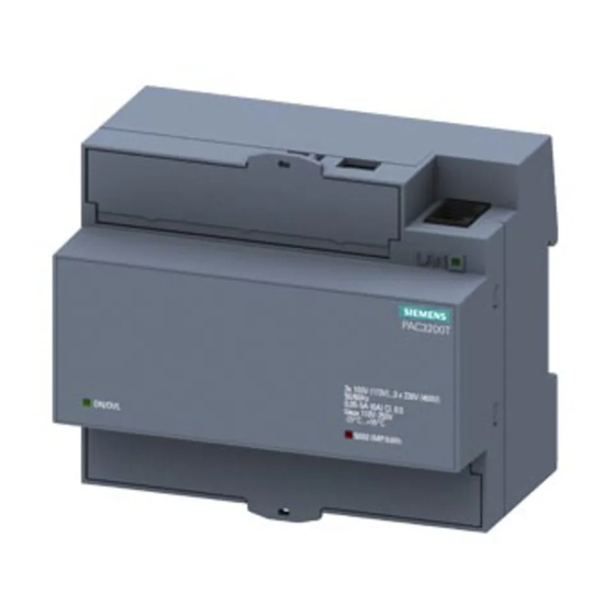
Introduction Components The package includes: • PAC3200T • PAC3200T operating instructions Available accessories • SENTRON powerconfig (https://sie.ag/3x7KffS) software • SENTRON powermanager (https://sie.ag/3NAGreg) software • External Display DSP800. The display shows values of up to 8x PAC3200T. MLFB 3VA9987-0TD10 3VA9977-0TD10 Equipment Manual, 09/2022, L1V30415168B-03... -
Page 10: Latest Information
Should additional information be desired, or should particular problems arise that are not discussed in enough detail in the operating instructions, please contact Technical Support (https://www.siemens.com/lowvoltage/technical-support) for the information you require. Equipment Manual, 09/2022, L1V30415168B-03... -
Page 11: Security Information
To keep up to date with all the latest product updates, subscribe to the Siemens Industrial Security RSS Feed at (https://www.siemens.com/industrialsecurity). Equipment Manual, 09/2022, L1V30415168B-03... -
Page 12: Open Source Software
93009 Regensburg Germany You will find Technical Support under. Keyword: Open Source Request (please specify Product name and version, if applicable) SIEMENS may charge a handling fee of up to 5 EUR to fulfil the request. Equipment Manual, 09/2022, L1V30415168B-03... -
Page 13: Advanced Training Courses
Product or any OSS components contained in it if they are modified or used in any manner not specified by SIEMENS. The license conditions may contain disclaimers that apply between you and the respective licensor. -
Page 15: Description
Description Features The PAC3200T is a measuring device for measuring the basic electrical variables in low- voltage power distribution. The device is capable of single-phase, two-phase, or three-phase measurement and can be used in three- or four-wire TN, TT and IT networks. The PAC3200T is mounted on a DIN rail. - Page 16 Description 2.1 Features Interfaces • Ethernet interface • Digital Input • Digital output A description of the inputs and outputs can be found in section "Digital inputs and outputs (Page 23)". Security • Hardware write protection • Access protection IP filter •...
-
Page 17: Measuring Inputs
Description 2.2 Measuring inputs Measuring inputs Current measurement NOTICE AC current measurement only. The device is not suitable for measuring DC current. PAC3200T is designed for: • Measuring current of 5 A for connecting standard current transformers. Each current measuring input can take a continuous load of 10 A. A momentary overcurrent of up to 100 A and a duration of 1 s is possible. - Page 18 Description 2.2 Measuring inputs Connection types Five connection types have been provided. The device can measure in single-phase, two- phase, or three-phase mode and can be used in three- or four-wire TN, TT and IT networks. Table 2- 1 Available connection types Short code Connection type 3P4W (factory setting)
- Page 19 Description 2.2 Measuring inputs Connection type Avail. Avail. Avail. Avail. Avail. 3P4W 3P3W 3P4WB 3P3WB 1P2W Measured variable Apparent power L ✓ — — — — Apparent power L ✓ — — — — Active power L ✓ — ✓ —...
- Page 20 Description 2.2 Measuring inputs Connection type Avail. Avail. Avail. Avail. Avail. 3P4W 3P3W 3P4WB 3P3WB 1P2W Measured variable Date/time ✓ ✓ ✓ ✓ ✓ Total active energy import (tariff 1) ✓ ✓ ✓ ✓ ✓ Total active energy import (tariff 2) ✓...
- Page 21 Description 2.2 Measuring inputs Connection type Avail. Avail. Avail. Avail. Avail. 3P4W 3P3W 3P4WB 3P3WB 1P2W Measured variable Total active energy import (tariff 1) ✓ ✓ ✓ ✓ ✓ Total active energy import (tariff 2) ✓ ✓ ✓ ✓ ✓ Total active energy export (tariff 1) ✓...
-
Page 22: Averaging Measured Values
Description 2.3 Averaging measured values Averaging measured values Instantaneous values are averaged over defined time periods in order to generate measured value profiles. The average values can be read out and stored for this purpose. This reduces the communication load and the storage requirements on downstream servers. The PAC3200T device has two average value generators, which can be parameterized independently. - Page 23 Description 2.4 Power demands and counters In addition to the possibility of a complete readout, the measured values of the last completed period can also be read out. These are only available during the demand period that is currently running. (See Modbus map, register 545 ff) This entry comprises: •...
-
Page 24: Energy Counters
Description 2.4 Power demands and counters 2.4.2 Energy counters Energy counter Available energy counters of the PAC3200T measuring device: Tariff 1 Tariff 2 Total (T1 + T2) Active energy Import Total Secondary value Export Total Secondary value Reactive energy Import Total kvarh Export... -
Page 25: History Of Active Energy Consumption
Description 2.5 History of active energy consumption History of active energy consumption Based on selected recordings of energy consumption over time, users can perform a targeted analysis of their energy consumption for the purpose of optimizing their energy usage. The power monitoring devices have a daily energy counter and a monthly energy counter. •... -
Page 26: Digital Input
Description 2.6 Digital inputs and outputs 2.6.1 Digital Input The following functions can be assigned to the digital input: • Status monitoring: Capturing statuses of connected signal encoders • Tariff switching for two-tariff counters • Synchronization of the measuring period by means of the synchronization pulse of a system control center or other device. -
Page 27: Digital Output
Description 2.6 Digital inputs and outputs 2.6.2 Digital output The following functions can be assigned to the digital output: • Not used: The digital output is deactivated. • Device ready for operation: With the device ready for operation the digital output is ON. •... - Page 28 Description 2.6 Digital inputs and outputs Wiring The digital output is passive and implemented exclusively as a switch. Implementation of the pulse function corresponds to the IEC 62053-31 standard. Pulse length, turn-off time ① Pulse length ② Turn-off time Figure 2-3 Pulse length and turn-off time •...
-
Page 29: Communication
Description 2.7 Communication Communication The device is equipped with the Ethernet interface. The Ethernet interface facilitates communication via the following protocols: • Modbus TCP The device can be configured via Modbus TCP and measured data read out. • Web server (HTTP) This protocol can only be used to read out the measured values via the web browser. -
Page 31: Mounting
Mounting Introduction WARNING The use of damaged devices may result in death, serious injury, or property damage. Do not install or start up damaged devices. Installation location The PAC3200T device is mounted on a TH35 rail (complying with EN 60715) and is intended for installation in permanently installed systems within closed rooms. -
Page 32: Installation Steps
Mounting 3.2 Installation steps Installation steps Proceed as follows to install the PAC3200T on the DIN rail: Procedure Removal Tools You require the following tools to remove the device: • Slotted screwdriver Procedure Equipment Manual, 09/2022, L1V30415168B-03... -
Page 33: Connection
Connection Safety notes DANGER Hazardous voltage. Will cause death, serious personal injury, or equipment damage. Turn off and lock out all power supplying this equipment before working on this device. DANGER Open transformer circuits will result in electric shock and arc flash hazards. Will cause death, serious personal injury, or equipment damage. - Page 34 Connection 4.1 Safety notes CAUTION Voltage input conductors may be damaged. The fuses in the voltage measuring inputs are only used for cable protection. Selection of the fuse depends on the supply cable dimensioning. All commercially available fuses and automatic circuit breakers up to 16 A (C) or 20 A (B) can be used. Observe the applicable regulations when selecting the fuse.
- Page 35 Connection 4.1 Safety notes Note Only qualified personnel are allowed to install, commission or service this device. • Wear the prescribed protective clothing. Observe the general equipment regulations and safety regulations for working with high-voltage installations (e.g. DIN VDE, NFPA 70E, as well as national or international regulations).
-
Page 36: Connections
Connection 4.2 Connections Connections All terminals are fitted with sealable terminal covers. Figure 4-1 Pin assignment Connection Function ① ↑k Current transformer connection I , input ° ② IL1 l↓ Current transformer connection I , output ③ ↑k Current transformer connection I , input °... -
Page 37: Connection Examples
Connection 4.3 Connection examples Connection examples Some connection examples for the following types of connection are listed below: • 3P4W - 3 phases, 4 conductors • 3P3W - 3 phases, 3 conductors • 3P4WB - 3 phases, 4 conductors with balanced load •... - Page 38 Connection 4.3 Connection examples Connection examples (1) Three-phase measurement, four conductors, unbalanced load, without voltage transformer, with three current transformers Connection type 3P4W The fuses are only used for cable protection. All commercially available fuses and automatic circuit breakers up to 16 A (C) or 20 A (B) can be used. Install a short-circuit device.
- Page 39 Connection 4.3 Connection examples (3) Three-phase measurement, four conductors, balanced load, without voltage transformer, with one current transformer Connection type 3P4WB The fuses are only used for cable protection. All commercially available fuses and automatic circuit breakers up to 16 A (C) or 20 A (B) can be used. Install a short-circuit device.
- Page 40 Connection 4.3 Connection examples (5) Three-phase measurement, three conductors, unbalanced load, without voltage transformer, with three current transformers Connection type 3P3W The fuses are only used for cable protection. All commercially available fuses and automatic circuit breakers up to 16 A (C) or 20 A (B) can be used. Install a short-circuit device.
- Page 41 Connection 4.3 Connection examples (7) Three-phase measurement, three conductors, unbalanced load, without voltage transformer, with two current transformers Connection type 3P3W The fuses are only used for cable protection. All commercially available fuses and automatic circuit breakers up to 16 A (C) or 20 A (B) can be used. Install a short-circuit device.
- Page 42 Connection 4.3 Connection examples (9) Three-phase measurement, three conductors, balanced load, without voltage transformer, with one current transformer Connection type 3P3WB The fuses are only used for cable protection. All commercially available fuses and automatic circuit breakers up to 16 A (C) or 20 A (B) can be used. Install a short-circuit device.
- Page 43 Connection 4.3 Connection examples (11) Two-phase measurement, three conductors, unbalanced load, without voltage transformer, with two current transformers Connection type 3P4W The fuses are only used for cable protection. All commercially available fuses and automatic circuit breakers up to 16 A (C) or 20 A (B) can be used. Install a short-circuit device.
-
Page 44: Connecting The Ethernet Communication Cable
Connection 4.4 Connecting the Ethernet communication cable Connecting the Ethernet communication cable Always use a shielded cable for the Ethernet data cable. 1. Plug the RJ45 cable connector into the RJ45 device socket until the connector engages in the socket. 2. - Page 45 Connection 4.4 Connecting the Ethernet communication cable Version Ground the Ethernet cable. To do this, expose the foil shield of the cable. Connect the exposed shield to a suitable grounding point on the control cabinet, preferably a shielding bus. • Be careful not to damage the foil shield of the cable when removing the cable jacket. •...
-
Page 47: Operation
Operation Device interface 5.1.1 Displays and operator controls The front of the PAC3200T contains the following displays and operator elements. ① SW button ② LED for Ethernet: Link / Activity • LED is illuminated: Data connection available • LED flashes: Data is being transferred •... -
Page 48: Sw Button
In addition to cost savings through optimized consumption, you ensure increased resilience with the monitoring of power supply systems and network quality in infrastructure and industrial plants. You can find more information on the internet. • Website (https://support.industry.siemens.com/cs/ww/en/view/109764480) • powerconfig software (https://sie.ag/3x7KffS) • powermanager software (https://sie.ag/3NAGreg) Equipment Manual, 09/2022, L1V30415168B-03... -
Page 49: Powermanager
Operation 5.2 Supporting software 5.2.1 powermanager Using the powermanager energy management software energy data of the PAC3200T power monitoring device can be acquired, monitored, evaluated, displayed and archived. powermanager offers the following functions for this: • Tree view of the customer's system (project tree) •... -
Page 50: Powerconfig
Operation 5.2 Supporting software 5.2.2 powerconfig The powerconfig software is the combined commissioning and service tool for communication-capable measuring devices and circuit breakers from the SENTRON family. The PC-based tool facilitates parameterization of the devices, resulting in substantial time savings, particularly when several devices have to be set up. Using powerconfig, measuring devices from the 7KM PAC series can be parameterized and operated via various communication interfaces, and measured values can be documented and monitored. -
Page 51: Web Server
Operation 5.3 Protection against manipulation 5.2.3 Web server The device can be read out with a PC/notebook via a website using the web server integrated in the device. Communication takes place via HTTP. The web server provides the following functions: •... -
Page 52: Password Protection
Operation 5.3 Protection against manipulation 5.3.2 Password protection Password protection prevents write access via the communication interfaces, in particular: • Changing of device settings, including password. • Changing and deletion of values/parameters. • Deletion of data and memory content. • Resetting to factory settings. Activation/deactivation of the password function is possible via the "powerconfig"... -
Page 53: Housing Seal And Sealing
Operation 5.3 Protection against manipulation 5.3.6 Housing seal and sealing Seal label The seal label protects the device from unauthorized access and possible manipulation inside the device. The device has two seal labels. The seal is multilayered. After removing or damaging the sticker, the word "Void"... -
Page 55: Commissioning
Commissioning Overview Prerequisites • The device has been installed. • The device has been connected in accordance with the possible connection methods. • Ethernet connection has been established. Steps for starting up the device 1. Apply the supply voltage 2. Parameterize the device using the powerconfig software 3. -
Page 56: Applying The Supply Voltage
Commissioning 6.2 Applying the supply voltage Applying the supply voltage A supply voltage is required to operate the device. Please consult the technical data or the rating plate for the type and level of the possible supply voltage. Refer also to the diagram Connections (Page 34) and Safety instructions NOTICE The wrong system connection can damage the device. -
Page 57: Setting Basic Parameters With Powerconfig
Commissioning 6.3 Parameterizing the device 6.3.1 Setting basic parameters with powerconfig 6.3.1.1 Establish connection to the device (via Ethernet) In order to establish a connection to the PAC3200T via Ethernet, proceed as follows: 1. Connect the device to the PC or network via the Ethernet interface. 2. -
Page 58: Communication Parameters
Commissioning 6.3 Parameterizing the device 6.3.1.2 Communication parameters Communication parameters Setting the communication parameters in powerconfig: 1. In menu item "Views", select the sub-menu "Communication". The "Communication" window opens. 2. Move the "Locked" slider in the "Communication" window. After it has been moved, the text of the slider changes to "Unlocked". 3. -
Page 59: Setting Basic Parameters
Commissioning 6.3 Parameterizing the device 6.3.1.4 Setting basic parameters Basic parameters are all those settings concerning the measuring inputs. "Connection type" parameter The "Connection type" parameter limits the total number of measured variables. The input circuit of the device must correspond to the parameterized connection type. Inform the device of the connection type used by entering the connection type code in the device settings. - Page 60 Commissioning 6.3 Parameterizing the device "Voltage Input" parameter The "voltage input" parameter specifies the values for the voltage input. Which values have to be set depends on the type of measurement. Selection Range Factory setting Voltage transformers Is voltage measurement performed via the voltage transformer? Yes: •...
-
Page 61: Extended (Further Parameters)
Commissioning 6.3 Parameterizing the device Selection Range Factory setting Minimum current The minimum current indicates the percentage of the upper measuring range limit from which the current measurement will start. Invert current The device interprets the current direction opposite to the wiring. - Page 62 Commissioning 6.3 Parameterizing the device "Security" parameter With the following parameters, write access to the device settings of the PAC3200T is blocked. The protection intervenes in case of the following actions: • Load to device • Reset maximum • Reset minimum •...
- Page 63 Commissioning 6.3 Parameterizing the device "Password protection" parameter Write access is only possible if password information is used. The password is only required when the "Password Protection" parameter is activated. As soon as the password has been entered once for the device, it is not requested again. The set password can be deleted from the memory in menu item "Password management".
- Page 64 Commissioning 6.3 Parameterizing the device "Hardware write-protection" parameter The hardware write protection prevents write access to the device. In order to gain write access, the hardware write protection must be deactivated directly on the device. Selection Range Factory setting Hardware write OFF: Hardware write protection is deactivated.
- Page 65 Commissioning 6.3 Parameterizing the device "Limits" parameter With the "Limits" parameter the monitoring of up to 6 limit values (Limit 0 to Limit 5) can be set. The "Result Logic Array" limit value comprises limits 0 to 5. Selection Range Factory setting Monitoring...
- Page 66 Commissioning 6.3 Parameterizing the device Figure 6-1 Effect of delay and hysteresis in case of limit violation See also Setting basic parameters (Page 57) Equipment Manual, 09/2022, L1V30415168B-03...
- Page 67 Commissioning 6.3 Parameterizing the device "Result Logic Array" parameter The device can be used to monitor the violation of up to 6 limit values. If a limit value is violated, specific actions can be triggered. In addition, the limit values can be combined with each other using a logic operation.
- Page 68 Commissioning 6.3 Parameterizing the device Example: LIM0, LIM1, LIM3 and LIM5 are to be linked to one another with the following logic: Selection of the operators: op0: AND (Λ) op1: AND (Λ) op2: ---- op3: AND (Λ) op4: ---- op5: OR (V) Formula: (((((AND LIM0 AND LIM1) ---- LIM2) AND LIM3) ---- LIM4) OR LIM5) = RLO Simplified representation: ((LIM0 Λ...
- Page 69 Commissioning 6.3 Parameterizing the device "Average value" parameter With appropriate aggregated average values, consumers can carry out a targeted optimization of their energy consumption. Instantaneous values are averaged over defined time periods in order to generate aggregated average values. For this purpose, measured values are read out via the communication and stored.
- Page 70 Commissioning 6.3 Parameterizing the device Selection Range Factory setting Usage type Not used: Not used Digital input is deactivated. Input pulse count: Counting of input pulses. Note: The universal counter must also be parameterized for pulse counting. Set the parameter "Advanced > Universal Counter" to "Digital Input".
- Page 71 Commissioning 6.3 Parameterizing the device "Digital output" parameter The following functions can be assigned to the "Digital output" parameter: • Energy pulse output; can be programmed for active or reactive energy pulses • Indication of the direction of rotation • Operating state display of the device •...
- Page 72 Commissioning 6.3 Parameterizing the device Selection Range Factory setting Pulses per unit Number of pulses, energy unit (kWh/kvarh), that are exported. (only for: energy pulse) Range: 1 to 4000 Output pulse Range: 1; 10; 100; 1000 divider (only for: energy pulse) Pulse duration Duration of the energy pulses...
- Page 73 Commissioning 6.3 Parameterizing the device "Power demand" parameter The "power demand" parameter permits the following device settings: Selection Range Factory setting Time period The time period records the duration of the period in minutes. Range: 1 min to 60 min Synchronization Setting of the synchronization mode: mode...
-
Page 75: Service And Maintenance
For an update, the write protection and password protection must be temporarily disabled. Please ensure that the environment is safe. The last devices settings made remain unchanged. The current firmware can be downloaded via the Siemens homepage (https://sie.ag/3Q8I2tn). Equipment Manual, 09/2022, L1V30415168B-03... -
Page 76: Troubleshooting Guide
If the device fault cannot be remedied by the measures given above, the device is probably defective. More help can be found on the Internet. (https://www.siemens.de/lowvoltage/technical- assistance) If the device is defective, please proceed as follows: • See chapter Warranty (Page 75) if the device has become defective within the warranty period. -
Page 77: Warranty
Procedure Note Loss of warranty. If you open the device, you will invalidate the Siemens warranty. Return faulty or damaged devices to Siemens. If the device is faulty or damaged, proceed as follows (only during the warranty period): 1. Remove the device; refer to section Removal (Page 30). - Page 78 Service and maintenance 7.5 Warranty Disposal of waste electronic equipment Waste electronic equipment must not be disposed of as unsorted municipal waste, e.g. household waste. When disposing of waste electronic equipment, the current local national/international regulations must be observed. Equipment Manual, 09/2022, L1V30415168B-03...
-
Page 79: Technical Data
Technical data Technical data Device configuration • 1 optically isolated digital input • 1 optically isolated digital output • 1 Ethernet interface for connecting to the PC or network Measurement Only for connection to AC voltage systems Measuring method For voltage measurement True root-mean-square measurement (TRMS) For current measurement True root-mean-square measurement (TRMS) - Page 80 Technical data 8.1 Technical data Measuring inputs for voltage Measuring inputs Voltage U 100 V / 173 V AC, 50 / 60 Hz n L-N / L-L 230 V / 400 V AC, 50 / 60 Hz Max. measurable voltage Voltage L-N 230 V 3AC (+20%) Voltage L-L...
- Page 81 Technical data 8.1 Technical data Measuring accuracy Applicable standards: • IEC 61557-12 • IEC 62053-22 • IEC 62053-23 Measured variable Accuracy class Voltage 0.5 (IEC 61557-12) Current 0.5 (IEC 61557-12) Neutral conductor current (calculated) 1 (IEC 61557-12) Total apparent power 0.5 (IEC 61557-12) Total active power 0.5 (IEC 61557-12)
- Page 82 Technical data 8.1 Technical data Digital output Digital output Number Type Passive Design/function Switching output or pulse output Maximum switching voltage 30 V Output current For signal "1" Depends on the load and the external power supply Continuous load ≤50 mA (thermal overload protection) Transient overload ≤130 mA for 100 ms For signal "0"...
- Page 83 Technical data 8.1 Technical data Voltage and supply connection: V1; V2; V3; VN; L+; N- Rigid 1 x 0.2 ... 6.0 1 x 24 ... 10 2 x 0.2 ... 1.5 2 x 24 ... 16 Flexible 1 x 0.2 ... 4.0 1 x 24 ...
- Page 84 Technical data 8.1 Technical data Degree of protection and protection class Degree of protection and protection class Protection class Safety class II Degree of protection according to IEC 60529 Front area IP40 Termination area IP20 If higher degree of protection requirements are placed on the application engineering, the customer must take suitable measures.
- Page 85 Technical data 8.1 Technical data Relative humidity in relation to ambient temperature The maximum relative humidity is 80% at temperatures up to 31 °C, decreasing linearly down to 50% relative humidity at 40 °C. Equipment Manual, 09/2022, L1V30415168B-03...
- Page 86 (https://support.industry.siemens.com/cs/ww/en/ps/7KM3200-0CA01-1AA0/cert). • Approval for Great Britain • Approvals for Australia and New Zealand RCM (Regulatory Compliance Mark) • Approval for Eurasian Economic Union • Approvals for UL and CSA market See also Siemens Support website (https://sie.ag/39jLm4r) Equipment Manual, 09/2022, L1V30415168B-03...
-
Page 87: Labeling
Technical data 8.2 Labeling Labeling Labels on the housing of the PAC3200T CE marking (Europe) UL marking (USA) Electrical installation and maintenance by qualified personnel only EAC marking (Eurasian Economic Union) Protective insulation – device of class II General warning symbol Risk of electric shock RCM test symbol (Australia / New Zealand) The device must not be disposed of with general domestic waste. -
Page 89: Dimensional Drawings
Dimensional drawings Frame dimensions Equipment Manual, 09/2022, L1V30415168B-03... -
Page 91: Appendix
Appendix Modbus TCP Detailed information about Modbus TCP can be found on the Modbus website (http://www.modbus.org). A.1.1 Function codes Function codes control the data exchange. In doing so, a function code tells the slave which action it is to take. If an error occurs, the most significant bit (MSB) is set in the FC byte of the response frame. -
Page 92: Modubs Exception Codes
Appendix A.1 Modbus TCP A.1.2 Modubs exception codes Overview Table A- 2 Modubs exception codes Exception codes Name Meaning Remedy Illegal Illegal function: Check which function Function codes are supported. • The function code in the request is not a permissible action for the slave. -
Page 93: Modbus Measured Variables With The Function Codes 0X03 And 0X04
Appendix A.1 Modbus TCP A.1.3 Modbus measured variables with the function codes 0x03 and 0x04 Addressing the measured variables You can use the Modbus function codes 0x03 and 0x04 on all the measured variables listed below. Note Error in the case of inconsistent access to measured values. Please ensure the start offset of the register is correct when making read accesses. - Page 94 Appendix A.1 Modbus TCP Offset Number Name Format Unit Value range Access registers Reactive power L3 Float — Power factor L1 Float — 0 ... 1 Power factor L2 Float — 0 ... 1 Power factor L3 Float — 0 ... 1 THD-R voltage L1 Float 0 ...
- Page 95 Appendix A.1 Modbus TCP Offset Number Name Format Unit Value range Access registers Max. THD-R voltage L2 Float 0 ... 100 Max. THD-R voltage L3 Float 0 ... 100 Max. THD-R current L1 Float 0 ... 100 Max. THD-R current L2 Float 0 ...
- Page 96 Appendix A.1 Modbus TCP Offset Number Name Format Unit Value range Access registers Limit violations * Unsigned — Byte 3 long Bit 0 = Limit 0 Byte 3 Bit 1 = Limit 1 Byte 3 Bit 2 = Limit 2 Byte 3 Bit 3 = Limit 3 Byte 3...
- Page 97 Appendix A.1 Modbus TCP Offset Number Name Format Unit Value range Access registers Max. displacement angle L3 Float — — (COS phi) Max. displacement angle Float — — SUM (COS phi) Min. displacement angle L1 Float — — (COS phi) Min.
- Page 98 Appendix A.1 Modbus TCP Offset Number Name Format Unit Value range Access registers Reactive energy import Float varh — current period Active energy export current Float — period Reactive energy export Float varh — current period Length of demand period Unsigned —...
- Page 99 Appendix A.1 Modbus TCP Offset Number Name Format Unit Value range Access registers Active energy import tariff 2 Double — Active energy export tariff 1 Double — Active energy export tariff 2 Double — Reactive energy import Double varh — tariff 1 Reactive energy import Double...
- Page 100 Appendix A.1 Modbus TCP Offset Number Name Format Unit Value range Access registers L3 active energy import Double — tariff 1 L3 active energy import Double — tariff 2 L3 active energy export Double — tariff 1 L3 active energy export Double —...
- Page 101 Appendix A.1 Modbus TCP Offset Number Name Format Unit Value range Access registers 2827 L1 active energy - export Float varh — tariff 2 2829 L1 reactive energy - import Float — tariff 1 2831 L1 reactive energy - import Float —...
- Page 102 Appendix A.1 Modbus TCP Offset Number Name Format Unit Value range Access registers 2883 Secondary total active energy Float — - export 2885 Total active energy import Float — 2887 Total active energy export Float — The following tables contain further details of all measured variables indicated by a *. Equipment Manual, 09/2022, L1V30415168B-03...
-
Page 103: Modbus Measured Variables With Function Code 0X14
Appendix A.1 Modbus TCP A.1.4 Modbus measured variables with function code 0x14 Addressing the measured variables The measured variables listed below can be read out via Modbus function code 0x14 "Read File Record" in two steps. These are the average values calculated by the device. The device can calculate the average values in two steps: •... - Page 104 Appendix A.1 Modbus TCP File Offset Address Number of Name Format Access (FC0x14) address FC: 0x03 0x04 registers 30021 I_L3 Float 30023 VA_L1 Float 30025 VA_L2 Float 30027 VA_L3 Float 30029 P_L1 Float 30031 P_L2 Float 30033 P_L3 Float 30035 VARQ1_L1 Float 30037...
- Page 105 Appendix A.1 Modbus TCP File Offset Address Number of Name Format Access (FC0x14) address FC: 0x03 0x04 registers 30259 Flags Aggregation Stage n Uint32 30261 max_V_L1 Float 30263 max_V_L2 Float 30265 max_V_L3 Float 30267 max_V_L12 Float 30269 max_V_L23 Float 30271 max_V_L31 Float 30273...
- Page 106 Appendix A.1 Modbus TCP File Offset Address Number of Name Format Access (FC0x14) address FC: 0x03 0x04 registers 30349 reserved Float 30351 reserved Float 30353 reserved Float 30355 reserved Float 30357 max_THDV_L12 Float 30359 max_THDV_L23 Float 30361 max_THDV_L31 Float 30363 reserved 30513 Time stamp Aggregation Stage n...
- Page 107 Appendix A.1 Modbus TCP File Offset Address Number of Name Format Access (FC0x14) address FC: 0x03 0x04 registers 30605 reserved Float 30607 reserved Float 30609 reserved Float 30611 reserved Float 30613 min_THDV_L12 Float 30615 min_THDV_L23 Float 30617 min_THDV_L31 Float 30619 reserved File Offset...
- Page 108 Appendix A.1 Modbus TCP File Offset Address Number of Name Format Access (FC0x14) address FC: 0x03 0x04 registers 31067 VA_SUM Float 31069 P_SUM Float 31071 VARQ1_SUM Float 31073 PF_SUM Float 31075 V_BAL Float 31077 I_BAL Float 31079 Float 31081 COS1_L1 Float 31083 COS1_L2...
- Page 109 Appendix A.1 Modbus TCP File Offset Address Number of Name Format Access (FC0x14) address FC: 0x03 0x04 registers 31305 max_THDV_L2 Float 31307 max_THDV_L3 Float 31309 max_THDI_L1 Float 31311 max_THDI_L2 Float 31313 max_THDI_L3 Float 31315 max_FREQ Float 31317 max_V_LN_AVG Float 31319 max_V_LL_AVG Float 31321...
- Page 110 Appendix A.1 Modbus TCP File Offset Address Number of Name Format Access (FC0x14) address FC: 0x03 0x04 registers 31543 min_P_L2 Float 31545 min_P_L3 Float 31547 min_VARQ1_L1 Float 31549 min_VARQ1_L2 Float 31551 min_VARQ1_L3 Float 31553 min_PF_L1 Float 31555 min_PF_L2 Float 31557 min_PF_L3 Float 31559...
-
Page 111: Active Energy History With Modbus Function Code 0X14
Appendix A.1 Modbus TCP A.1.5 Active energy history with Modbus function code 0x14 The active energy counters listed below can be read out via Modbus function code 0x14 "Read File Record". • The daily energy counter (file number 90) records the active energy for each day of the preceding two months. - Page 112 Appendix A.1 Modbus TCP File Offset Address Length Name Format Access (FC0x14) address FC0x03 FC0x04 32057 TS of day – 9 UNIX_TS (UTC) R 32059 Work portion Tariff 1 Float 32061 Work portion Tariff 2 Float 32063 TS of day – 10 UNIX_TS (UTC) R 32065 Work portion Tariff 1...
- Page 113 Appendix A.1 Modbus TCP File Offset Address Length Name Format Access (FC0x14) address FC0x03 FC0x04 32147 TS of day – 24 UNIX_TS (UTC) R 32149 Work portion Tariff 1 Float 32151 Work portion Tariff 2 Float 32153 TS of day – 25 UNIX_TS (UTC) R 32155 Work portion Tariff 1...
- Page 114 Appendix A.1 Modbus TCP File Offset Address Length Name Format Access (FC0x14) address FC0x03 FC0x04 32237 TS of day – 39 UNIX_TS (UTC) R 32239 Work portion Tariff 1 Float 32241 Work portion Tariff 2 Float 32243 TS of day – 40 UNIX_TS (UTC) R 32245 Work portion Tariff 1...
- Page 115 Appendix A.1 Modbus TCP File Offset Address Length Name Format Access (FC0x14) address FC0x03 FC0x04 32327 TS of day – 54 UNIX_TS (UTC) R 32329 Work portion Tariff 1 Float 32331 Work portion Tariff 2 Float 32333 TS of day – 55 UNIX_TS (UTC) R 32335 Work portion Tariff 1...
- Page 116 Appendix A.1 Modbus TCP File Offset Address Length Name Format Access (FC0x14) address FC0x03 FC0x04 32401 Error state Bool 32403 TS actual period UNIX_TS (UTC) R 32405 Work portion this month Tariff 1 Float 32407 Work portion this month Tariff 2 Float 32409 TS of month –...
- Page 117 Appendix A.1 Modbus TCP File Offset Address Length Name Format Access (FC0x14) address FC0x03 FC0x04 32491 Work portion Tariff 2 Float 32493 TS of month – 15 UNIX_TS (UTC) R 32495 Work portion Tariff 1 Float 32497 Work portion Tariff 2 Float 32499 TS of month –...
-
Page 118: Structure - Digital Input Status And Digital Output Status With The Function Codes 0X03 And 0X04
Appendix A.1 Modbus TCP A.1.6 Structure - Digital input status and digital output status with the function codes 0x03 and 0x04 The following are available via Modbus: • "Status of the digital input" • "Status of the digital output" Input status and output status of the PAC3200T Table A- 4 Structure - Status of the digital inputs and outputs, Modbus offset 207 and 209 Name... - Page 119 Appendix A.1 Modbus TCP Measuring channel 2: Active energy or active power export Description Number Can be used on " Data Log Identifier" Measuring channels 1 and 2 (energy 0x69 0x04, 0x05, 0x06 quantity) Measuring channel 1 (energy quantity) 0x6A 0x04, 0x05, 0x06 Measuring channel 2 (energy quantity) 0x6B...
- Page 120 Appendix A.1 Modbus TCP Reading out the profile data memory (load profile, daily profile, monthly profile, annual profile) Each of the profile data memories contains 2 measuring channels: • Measuring channel 1: Active energy or active power import • Measuring channel 2: Active energy or active power export A special feature of the load profile memory (demand period duration of 15 minutes) is that these channels are also available as •...
- Page 121 Appendix A.1 Modbus TCP Example of response frame Bytes in hex Description 00 00 00 00 00 64 01 MBAP Header Modbus user defined function code payload length in bytes (starting with the following byte to the end, excluding CRC) Data log identifier ->...
-
Page 122: Structure - Device Diagnostics And Device Status With The Function Codes 0X03 And 0X04
Appendix A.1 Modbus TCP A.1.8 Structure - Device diagnostics and device status with the function codes 0x03 and 0x04 Structure Table A- 5 Modbus offset 205, register 2: Structure device status and device diagnostics Byte Device status Type Bit mask Value range Access No synchronization pulse... -
Page 123: Modbus Status Parameters With The Function Code 0X02
Appendix A.1 Modbus TCP A.1.9 Modbus status parameters with the function code 0x02 Status parameters You can use the Modbus function code 0x02 on all the status parameters listed below. Table A- 6 Status parameters Offset Number of Name Format Value range Access registers... -
Page 124: Modbus Settings With The Function Codes 0X03, 0X04 And 0X10
Appendix A.1 Modbus TCP A.1.10 Modbus settings with the function codes 0x03, 0x04 and 0x10 Addressing the settings You can use the Modbus function codes 0x03 and 0x04 for read accesses and 0x10 for write accesses on all the settings parameters listed below. Table A- 7 Settings parameters Offset... - Page 125 Appendix A.1 Modbus TCP Table A- 8 Settings parameter for the digital input Offset Number of Name Unit Format Value range Access registers 50025 Digital input "Action" — Unsigned long Status only Pulse input On-peak/off-peak tariff switching Synchronization 50029 "Pulse input" mode —...
- Page 126 Appendix A.1 Modbus TCP Table A- 9 Settings parameter for the digital output Offset Number of Name Unit Format Value range Access registers 50033 Switching function — Unsigned long 0 ... 99 assignment to a vector group 50035 Digital output "Action" — Unsigned long Device ON Switching output...
- Page 127 Appendix A.1 Modbus TCP Table A- 10 Settings parameters for the universal counter source Offset Number of Name Unit Format Value range Access registers 50051 Universal counter — Unsigned long Digital input source Digital output Limit logic Limit 0 Limit 1 Limit 2 Limit 3 Limit 4...
- Page 128 Appendix A.1 Modbus TCP Offset Number of Name Unit Format Value range Access registers 23 = THDV_L3 24 = THDI_L1 25 = THDI_L2 26 = THDI_L3 27 = THDV_L12 28 = THDV_L23 29 = THDV_L31 30 = COS1_L1 31 = COS1_L2 32 = COS1_L3...
-
Page 129: Modbus Communication Parameters With The Function Codes 0X03, 0X04 And 0X10
Appendix A.1 Modbus TCP A.1.11 Modbus communication parameters with the function codes 0x03, 0x04 and 0x10 Addressing the communication parameters Table A- 13 Communication parameters Offset Number of Name Unit Format Applicable Value range Access registers Modbus function codes 62997 IP filter —... -
Page 130: Modbus Device Information With The Function Codes 0X03, 0X04 And 0X10
3A00 ... F6FF [64025] Specific Profile ID unsigned short [64026] Version of the I&M data 2 unsigned char 0.0 ... 255.255 [64027] Supported I&M data unsigned short 00 ... FF *) 42 stands for Siemens AG Equipment Manual, 09/2022, L1V30415168B-03... - Page 131 Appendix A.1 Modbus TCP Table A- 15 I&M 1-4 parameters with the function codes 0x03, 0x04 and 0x10 Offset Total Number of Name Format Value range Access registers registers per parameter Start offset [16] Plant identifier Char 32 ASCII 64028 [64044] [11] Location identifier...
-
Page 132: Modbus Command Parameters
Appendix A.1 Modbus TCP A.1.13 Modbus command parameters Addressing the command parameters You can apply the Modbus function code 0x06 to the command parameters. Table A- 16 Command parameters Offset Number Name Unit Format Value range Access registers 60000 Reset the device to the factory —... -
Page 133: Modbus Standard Device Identification With The Function Code 0X02
Appendix A.1 Modbus TCP Offset Number Name Unit Format Value range Access registers 60008 Switching outputs (if — unsigned short 0ffh ... 1ffh parameterized) Byte 0 Digital output 0.0 Byte 1 Byte 1 60009 Switching command for vector — unsigned short High 0 ... - Page 134 Equipment Manual, 09/2022, L1V30415168B-03...