Table of Contents
Advertisement
Quick Links
Advertisement
Table of Contents

Related Manuals for Siemens SENTRON PAC2200CLP


Summary of Contents for Siemens SENTRON PAC2200CLP
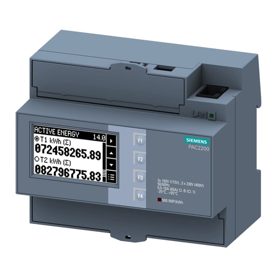
- Page 3 PAC2200CLP Introduction Description SENTRON Installation Connection 7KM power monitoring device PAC2200CLP Operation Commissioning Equipment Manual Service and maintenance Technical specifications Dimension drawings Appendix 06/2021 L1V30820585B-02...
- Page 4 Note the following: WARNING Siemens products may only be used for the applications described in the catalog and in the relevant technical documentation. If products and components from other manufacturers are used, these must be recommended or approved by Siemens. Proper transport, storage, installation, assembly, commissioning, operation and maintenance are required to ensure that the products operate safely and without any problems.
-
Page 5: Table Of Contents
Table of contents Introduction ............................7 Components of the product ....................7 Latest information ....................... 7 Security information ......................9 Open Source Software ......................9 Advanced training courses ....................10 Risk of manipulation ......................11 Description ............................13 Performance features ......................13 Measuring inputs ....................... - Page 6 Table of contents Removal ..........................38 Connection ............................39 Safety notes ........................39 Connections ........................41 Connection examples ......................43 Connecting the communication cable ................46 4.4.1 Ethernet communication cable ..................46 4.4.2 Grounding of the Ethernet cable ..................46 Operation .............................
- Page 7 Table of contents Labeling ..........................89 Dimension drawings ..........................91 Dimensional drawings ....................... 91 Appendix ............................. 93 Modbus TCP ........................93 A.1.1 Function codes ........................93 A.1.2 Modbus exception codes ....................94 A.1.3 Modbus measured variables with the function codes 0x03 and 0x04 ........95 A.1.4 Modbus measured variables with function codes 0x14, 0x03 and 0x04 ......
- Page 8 Table of contents PAC2200CLP Equipment Manual, 06/2021, L1V30820585B-02...
-
Page 9: Introduction
Introduction Components of the product The package includes: • PAC2200CLP power monitoring device • PAC2200CLP operating instructions Available accessories • powerconfig software (https://support.industry.siemens.com/cs/ww/en/view/63452759) • powermanager software (https://support.industry.siemens.com/cs/ww/en/view/109771760) Latest information Up-to-the-minute information You can find further assistance: on the Internet: Website (https://support.industry.siemens.com/my/ww/en/requests) - Page 10 Should additional information be desired, or should particular problems arise that are not discussed in enough detail in the operating instructions, please contact Technical Support (https://www.siemens.com/lowvoltage/technical-support) for the information you require. Safety-related symbols on the device...
-
Page 11: Security Information
To keep up to date with all the latest product updates, subscribe to the Siemens Industrial Security RSS Feed at (https://www.siemens.com/industrialsecurity). Open Source Software This product, solution or service ("Product") contains third-party software components. -
Page 12: Advanced Training Courses
Product or any OSS components contained in it if they are modified or used in any manner not specified by SIEMENS. The license conditions may contain disclaimers that apply between you and the respective licensor. -
Page 13: Risk Of Manipulation
Introduction 1.6 Risk of manipulation Risk of manipulation Note Risk of manipulation Several protective mechanisms can be activated in the device. In order to reduce the risk of manipulation occurring on the device, it is recommended that the protective mechanisms available in the device are activated: •... - Page 14 Introduction 1.6 Risk of manipulation PAC2200CLP Equipment Manual, 06/2021, L1V30820585B-02...
-
Page 15: Description
Description Performance features The PAC2200CLP is a power monitoring device for measuring the basic electrical variables in low-voltage power distribution. All the measured variables are shown on the PAC2200CLP display. The device is capable of single-phase, two-phase or three-phase measurement and can be used in TN, TT and IT systems. - Page 16 Description 2.1 Performance features • With load profile measurement conforming to statutory calibration regulations and national approval according to PTB-A 50.7 • Integrated 15-minute load profile memory with a storage depth for all billing-relevant data over 2 years • Daily, monthly and annual consumption of active energy for import and export over 10 years •...
- Page 17 Description 2.1 Performance features Security • Hardware write protection If you want to use the device for billing purposes, please refer to the notes at the end of this chapter. • Password protection • Access protection IP filter • Modbus TCP port, configurable •...
- Page 18 Description 2.1 Performance features MID-approved The devices have MID approval and national approval according to PTB-A50.7 for Germany. They are therefore suitable for the measurement and delimitation of power consumption quantities in conformance with statutory metering and calibration regulations according to Renewable Energy Act §62b.
-
Page 19: Measuring Inputs
Description 2.2 Measuring inputs Measuring inputs Current measurement NOTICE AC current measurement only The device is not suitable for measuring DC current. The 5 A device is designed for: • Measuring current of 5 A for connecting standard current transformers. Each current measuring input can take a continuous load of 10 A. - Page 20 Description 2.2 Measuring inputs Note Use of connection type 1P2W In order to obtain accurate measured values, phase L1 must be used for single-phase operation (1P2W). NOTICE Connection to the wrong supply voltage can cause irreparable damage to the device. Before connecting PAC2200CLP, it must be ensured that the local power supply conditions match the specifications on the nameplate.
-
Page 21: Functions For Delimiting Third-Party Quantities According To §62B Par. 1 Of The Renewable Energy Act
Description 2.3 Functions for delimiting third-party quantities according to §62b Par. 1 of the Renewable Energy Act Measured variable Display Apparent energy tariff T2 L1,L2,L3, ∑ ✓ ✓ 15-minute active energy profile import ✓ ✓ 15-minute active energy profile export ✓... -
Page 22: Navigating To Main Menu, Settings, Date/Time
Description 2.3 Functions for delimiting third-party quantities according to §62b Par. 1 of the Renewable Energy Act 2.3.1.1 Navigating to main menu, settings, date/time 2.3.1.2 Parameterization PAC2200CLP Equipment Manual, 06/2021, L1V30820585B-02... - Page 23 Description 2.3 Functions for delimiting third-party quantities according to §62b Par. 1 of the Renewable Energy Act Date: Shows the date currently set in the device. Format: Format used for display. Time: Shows the time currently set in the device. Time zone: This must be set correctly here based on the geographical time zone.
-
Page 24: Synchronization Errors
Description 2.3 Functions for delimiting third-party quantities according to §62b Par. 1 of the Renewable Energy Act SNTP status OK: The symbol of a filled circle is displayed if the last synchronization was successful. It changes to an empty circle as soon as a synchronization operation fails. 2.3.1.3 Synchronization errors If the time cannot be synchronized successfully, a flashing warning symbol is displayed on... - Page 25 Description 2.3 Functions for delimiting third-party quantities according to §62b Par. 1 of the Renewable Energy Act Scenario Effects Time in the event of a power failure As the device is supplied by the measuring voltage, it ceases to operate in this case.
-
Page 26: Logbook
Description 2.3 Functions for delimiting third-party quantities according to §62b Par. 1 of the Renewable Energy Act 2.3.2 Logbook Important changes which could influence the measurement or the storage of data in the load profile are recorded in this logbook. The reason, time and the OID of the affected demand period are stored for every entry along with the counter readings for import and export at the time of the event. -
Page 27: Examples Of Logbook Entries
Description 2.3 Functions for delimiting third-party quantities according to §62b Par. 1 of the Renewable Energy Act 2.3.2.2 Examples of logbook entries Detailed view of "Time zone" entry Detailed view of "Parameter" entry PAC2200CLP Equipment Manual, 06/2021, L1V30820585B-02... -
Page 28: Load Profile
Description 2.3 Functions for delimiting third-party quantities according to §62b Par. 1 of the Renewable Energy Act 2.3.3 Load profile The consumption values for active energy import (kWh) and active energy export (kWh) are stored in the device at 15-minute intervals, where they are retained for a period of 24 months. -
Page 29: Load Profile Overview
Description 2.3 Functions for delimiting third-party quantities according to §62b Par. 1 of the Renewable Energy Act 2.3.3.2 Load profile overview The "Load profile" menu shows the 15-minute load profile in conformance with PTB-A 50.7 as well as the daily, monthly and annual values for information. Line Value Description... - Page 30 Description 2.3 Functions for delimiting third-party quantities according to §62b Par. 1 of the Renewable Energy Act Detailed view of a single entry Detailed view line 2 with daily values Detailed view of a single entry Detailed view line 3 with monthly values Similar to detailed view of daily values, but with monthly values.
-
Page 31: Display With Invalid Values
Description 2.3 Functions for delimiting third-party quantities according to §62b Par. 1 of the Renewable Energy Act 2.3.3.4 Display with invalid values Invalid entries are marked with a "!" in front of the entry. Details about the reason can be found in the detailed view. PAC2200CLP Equipment Manual, 06/2021, L1V30820585B-02... -
Page 32: Averaging Measured Values
Description 2.4 Averaging measured values Averaging measured values 2.4.1 Averaging measured values Instantaneous values are averaged over defined time periods in order to generate measured value profiles. The average values can be read out and stored for this purpose. This reduces the communication load and the storage requirements on downstream servers. -
Page 33: Energy Counters
Description 2.4 Averaging measured values This entry comprises: • Time stamp at the end of the completed demand period (UTC) according to PTB-A50.7 • Unique ID • Real length of period (measurement duration) • Total active energy for import and export according to PTB-A50.7 •... - Page 34 Description 2.4 Averaging measured values Secondary value Apparent energy kVAh Total Secondary value Secondary values: Energy counter which does not take the transformer ratio into account during calculation. MID: MID registers are indicated in the menu by the MID mark. Marked registers are suitable for billing purposes.
-
Page 35: Digital Inputs And Outputs
Description 2.5 Digital inputs and outputs Digital inputs and outputs 2.5.1 Digital inputs and outputs The PAC2200CLP features the following inputs/outputs: • 1 digital input • 1 digital output 2.5.2 Digital input The following functions can be assigned to the digital input: •... -
Page 36: Digital Output
Description 2.5 Digital inputs and outputs 2.5.3 Digital output The following functions can be assigned to the digital output: • Not used Digital output is deactivated. • Device is ready for operation. The digital output is ON. • Remote control The digital input is remotely controlled. - Page 37 Description 2.5 Digital inputs and outputs Wiring The digital output is passive and implemented exclusively as a switch. Implementation of the pulse function corresponds to the IEC 62053-31 standard. Pulse length Turn-off time Figure 2-3 Pulse length and turn-off time •...
-
Page 38: Communication
Description 2.6 Communication Communication 2.6.1 Ethernet Permits communication via the following protocols: • Modbus TCP The device can be configured via Modbus TCP • Web server (HTTP) Protocol can be used to read out the measured values via web browser. •... -
Page 39: Installation
Installation Introduction WARNING The use of damaged devices may result in death, serious injury, or property damage. Do not install or start up damaged devices. Installation location The PAC2200CLP is installed on a TH35 standard mounting rail (acc. to EN 60715) and is designed for installation in permanently installed systems, switchgear cabinets or fuse boxes. -
Page 40: Installation Steps
Installation 3.2 Installation steps Installation steps Procedure Removal Tools You require the following tools to uninstall the device: • Slotted screwdriver Procedure PAC2200CLP Equipment Manual, 06/2021, L1V30820585B-02... -
Page 41: Connection
Connection Safety notes Notes DANGER Hazardous voltage Will cause death, serious personal injury, or equipment damage. Turn off and lock out all power supplying this equipment before working on this device. DANGER Open transformer circuits will result in electric shock and arc flash hazards Will cause death, serious personal injury, or equipment damage. - Page 42 Connection 4.1 Safety notes CAUTION Voltage input conductors may be damaged. The fuses in the voltage measuring inputs are only used for cable protection. Selection of the fuse depends on the supply cable dimensioning. All commercially available fuses and automatic circuit breakers up to 16 A (C) or 20 A (B) can be used. The relevant applicable regulations must be complied with when selecting the fuse.
-
Page 43: Connections
Connection 4.2 Connections Connections All terminals are fitted with sealable terminal covers Figure 4-1 PAC2200CLP (5A) connector pin assignments Connection Function IL1↑k , input IL1 l↓ , output IL2↑k , input IL2 l↓ , output IL3↑k , input IL3 l↓ , output Voltage V L1-N... - Page 44 Connection 4.2 Connections Figure 4-2 PAC2200CLP (65A) connector pin assignments Connection Function L1 ↑ L1 conductor input L1 ↓ L1 conductor output L2 ↑ L2 conductor input L2 ↓ L2 conductor output L3 ↑ L3 conductor input L3↓ L3 conductor output N↑...
-
Page 45: Connection Examples
Connection 4.3 Connection examples Connection examples Some connection examples for the following types of connection are listed below: • 1P2W - 1 phase, 2 conductors • 3P4W - 3 phases, 4 conductors The selection of the connection types in the device can differ according to the device version. For the 5 A device, it is only possible to measure the current with current transformers. - Page 46 Connection 4.3 Connection examples Connection examples for the 5 A device CAUTION Protection of the voltage measuring inputs On the 5 A device, the fuses in the voltage measuring inputs are only used for cable protection. Selection of the fuse depends on the supply cable dimensioning. All commercially available fuses and automatic circuit breakers up to 16 A (C) or 20 A (B) can be used.
- Page 47 Connection 4.3 Connection examples Connection example for the 65 A device (1) Single-phase measuring, two conductors, unbalanced load, with two current transformers Connection type 1P2W Figure 4-5 Direct connection to the low-voltage network. (2) Three-phase measurement, four conductors, direct connection to the low-voltage network Connection type 3P4W Figure 4-6...
-
Page 48: Connecting The Communication Cable
Connection 4.4 Connecting the communication cable Connecting the communication cable 4.4.1 Ethernet communication cable Always use a shielded cable for the Ethernet data cable. 1. Plug the RJ45 cable connector into the RJ45 device socket until the connector engages in the socket. - Page 49 Connection 4.4 Connecting the communication cable • Be careful not to damage the foil shield of the cable when removing the cable jacket. Fasten the exposed shield with a metal cable clamp or alternatively with a hose tie. The clamp must clasp around a large portion of the shield and provide good contact. •...
- Page 50 Connection 4.4 Connecting the communication cable PAC2200CLP Equipment Manual, 06/2021, L1V30820585B-02...
-
Page 51: Operation
Operation Device interface 5.1.1 Displays and operator controls The front of the PAC2200CLP device features the following displays and operator controls: ① Software pushbutton ② LED for Ethernet: Link / Activity • LED is illuminated: Data connection available • LED flashes: Data is being transferred •... -
Page 52: Sw Button
Operation 5.1 Device interface 5.1.2 SW button Devices connected to a network are to be protected against unauthorized remote access and possible manipulation. The physical access of the user to the device is confirmed with the SW button. In the following cases, the user is prompted to press the button: •... -
Page 53: Menu Navigation
Operation 5.2 Menu navigation Menu navigation The menu-based navigation is intuitive and self-explanatory. Only the basic structure of the menu-based navigation will be explained for this reason. To simplify the overview, menu screenshots are not included in the manual. The description and function of the individual parameters can be found in chapter Device parameterization (Page 60). -
Page 54: Setting Level
Operation 5.2 Menu navigation Using the keys you can scroll through the measured variables. key confirms the required selection and takes the device to the measured value level. In the "SETTINGS" menu option, the device is set to the "Setting level" by actuating the key. -
Page 55: Supporting Software
You can find more information on the internet. Website (https://support.industry.siemens.com/cs/ww/en/view/109764480) 5.3.1 powermanager Energy data of the PAC2200CLP power monitoring device can be measured, monitored, evaluated, displayed and archived using the powermanager energy management software. -
Page 56: Web Server
Operation 5.3 Supporting software • Display of the available device statuses and measured values in standardized views • Project-oriented storage of device data • Consistent operation and usability • Support of the various communication interfaces (Modbus RTU, Modbus TCP, PROFIBUS, PROFINET) •... -
Page 57: Advanced Training Courses
5.3.4 Advanced training courses Find out about training courses on offer on the following link. Training for Industry (https://www.sitrain-learning.siemens.com/DE/en/rw73138/Low- Voltage-Power-Distribution) Here you can choose from: • Web-based training courses (online, informative, free) • Classroom training courses (course attendance, comprehensive, subject to fee) •... -
Page 58: Password Protection
Operation 5.4 Protection against manipulation 5.4.2 Password protection Password protection prevents write access via the device interface and the communication interfaces, in particular: • Changing of device settings, including password. • Changing and deletion of values/parameters. • Deletion of data and memory content. •... -
Page 59: Hardware Write Protection
Operation 5.4 Protection against manipulation 5.4.3 Hardware write protection The hardware write protection prevents write access to the device, both via the communication interface and on the display. In order to gain write access, the hardware write protection must be deactivated directly on the device. - Page 60 Operation 5.4 Protection against manipulation PAC2200CLP Equipment Manual, 06/2021, L1V30820585B-02...
-
Page 61: Commissioning
Commissioning Overview Prerequisites • The device has been installed. • The device has been connected in accordance with the possible connection methods. Steps for starting up the device 1. Apply the measuring voltage 2. Parameterize the device 3. Check measured values Note Check the connections Incorrect connection can result in malfunctions and failure of the device. -
Page 62: Parameterizing The Device
Parameterizing with powerconfig You can download the powerconfig configuration software from the Industry Online Support Website ((https://support.industry.siemens.com/cs/ww/en/view/63452759) herunterladen.). Information and notes on how to use powerconfig can be found in the Online Help of the configuration software or by contacting Technical Support. - Page 63 Commissioning 6.3 Parameterizing the device 8. In menu item "Views", select the sub-menu "Parameters". The "Parameter" window is displayed. 9. In the "Properties" window, click on the "Load to PC" button. The configuration is loaded from the device to the PC. Parameterizing the device The parameters are entered and changed in offline mode.
- Page 64 Commissioning 6.3 Parameterizing the device "Security" parameter Activate security with powerconfig: 1. In menu item "Views", select the sub-menu "Security". The "Security" window is displayed. 2. In the menu item "Options", select "Activate online view". The "Security" window is refreshed. The following degrees of protection can be activated/deactivated –...
-
Page 65: Parameterization Via The Device Menu
Commissioning 6.3 Parameterizing the device Every repeated incorrect password entry results in an extension of the delay period between entry possibilities. Note If you have forgotten the password, please contact Technical Support. You will receive a new password from them. "Hardware write-protection"... - Page 66 Commissioning 6.3 Parameterizing the device "Basic settings" parameter Not available for 65 A devices. "Current input" parameter The "Current input" parameter specifies the values for the current input. When measuring via current transformer, the device must know the current conversion ratio. For this purpose, the primary and secondary current must be specified in the fields "PRIMARY CURRENT"...
- Page 67 Commissioning 6.3 Parameterizing the device "Date/Time" parameter The date and time can be set by using the "Date/time" option in the "Settings" menu. Selection Range Factory setting DATE Current date – The date format is defined in the FORMAT field. FORMAT DD.MM.YYYY (day –...
- Page 68 Commissioning 6.3 Parameterizing the device Selection Range Factory setting SNTP Protocol is used for transmitting and synchronizing the time. • OFF: SNTP function not active • ACTIVE: The device automatically requests the time from the NTP server. • BCST client: The device receives time telegrams which are sent from an NTP server.
- Page 69 Commissioning 6.3 Parameterizing the device )* Formula: Example: Pulses per unit: 50 Pulse divider: 100 Unit: kWh "Digital output" parameter The following functions can be assigned to the "Digital output" parameter: • Energy pulse output; can be programmed for active or reactive energy pulses •...
- Page 70 Commissioning 6.3 Parameterizing the device Selection Range Factory setting UNIT Selects the type of cumulative power and the import Counter Import value that triggers the pulse when that value is Active Energy reached. (kWh) • Counter Import Active Energy (kWh) •...
- Page 71 Commissioning 6.3 Parameterizing the device Selection Range Factory setting IP FILTER • OFF: IP filter deactivated • ON: Write access is rejected if the remote station is in another subnet. The IP filter, also called subnet firewall protection, is a configurable protection on the device.
- Page 72 Commissioning 6.3 Parameterizing the device Write access to the device settings can be prevented by means of a password. After the password has been entered once for the device, it is not requested again while the device is still at the "Settings" level. Password protection prevents the following actions: •...
- Page 73 Commissioning 6.3 Parameterizing the device "Write protection" parameter Selection Range Factory setting WRITE PROTECTION • Not active Yes: • Active PRESS SW The physical access of the user to the device is con- – firmed with the SW button. When activating or deactivating the write protection, the request "PRESS SW"...
- Page 74 Commissioning 6.3 Parameterizing the device The hardware write protection cannot be deactivated via a communications interface. The user must press the SW button directly on the device to activate or deactivate the hardware write protection function. Note After the PAC2200CLP has started up, check that it is functioning correctly. If you are capturing data for billing purposes, the hardware write protection must be activated and the terminal cover must be sealed.
-
Page 75: Service And Maintenance
Service and maintenance The device requires no maintenance. Cleaning Clean the device as required. Use a dry cloth for this. NOTICE Damage may result from use of detergents. Detergents can damage the device. Do not use detergents. Calibration The device has been calibrated by the manufacturer before shipping. Recalibration is not required provided the environmental conditions are maintained. - Page 76 If the device fault cannot be remedied by the measures given above, the device is probably defective. More help can be found on the Internet. Technical Assistance (https://www.siemens.com/support-request) If the device is defective, please proceed as follows: • See chapter Warranty (Page 75) if the device has become defective within the warranty period.
-
Page 77: Warranty
Loss of warranty If you open the device, you will invalidate the Siemens warranty. Only the manufacturer is permitted to carry out repairs to the devices. Return faulty or damaged devices to Siemens for repair or replacement. If the device is faulty or damaged, proceed as follows (only during the warranty period): 1. - Page 78 Service and maintenance 7.4 Warranty PAC2200CLP Equipment Manual, 06/2021, L1V30820585B-02...
-
Page 79: Technical Specifications
Technical specifications Technical specifications Device configuration • 1 optically isolated digital input • 1 optically isolated digital output • 1 Ethernet interface for connection to and configuring on the PC or network Measurement Only for connection to AC voltage systems Measuring method For voltage measurement True root-mean-square measurement (TRMS) - Page 80 Technical specifications 8.1 Technical specifications Measuring inputs Measuring category CAT III (acc. to IEC 61010-2-030) Input resistance (L-N) 1 MΩ Measuring inputs for current (5 A device) Only for connection to AC power systems via external current transformers (5 A device) Measuring inputs Rated current In I 1 A / 5 A...
- Page 81 Technical specifications 8.1 Technical specifications Measuring accuracy Applied standards: • IEC 61557-12 • IEC 62053-21 • IEC 62053-22 • IEC 62053-23 • EN 50470-3: Measured variable Accuracy class acc. to IEC 61557-12 (K55) Voltage Class 0.5 Current Class 0.5 Apparent power Class 1 Active power Class 1...
- Page 82 Technical specifications 8.1 Technical specifications Digital output Digital output Number Type Passive Design/function Switching output or pulse output Rated voltage 0 ... 30 V DC, typical 24 V DC (SELV or PELV sup- ply) Output current For signal "1" Depends on the load and the external power sup- Continuous load ≤50 mA (thermal overload protection) Transient overload...
- Page 83 Technical specifications 8.1 Technical specifications Connection elements The specified conductor cross-sections describe the capacity of the connection terminals. When selecting the conduction cross-sections, always pay attention to the possible current load and ensure adequate cable protection. Current, power supply 5 A device 65 A device Conductor cross-section for copper cable (Cu) Rigid...
- Page 84 Technical specifications 8.1 Technical specifications Communication ports Conductor cross-section for copper cable (Cu) Rigid 0.14 ... 1.5 mm² [AWG 26 ... 16] Flexible 0.14 ... 1.5 mm² [AWG 26 ... 16] Flexible with end sleeve, without plastic 0.25 ... 1.0 mm² sleeve [AWG 24 ...
- Page 85 Technical specifications 8.1 Technical specifications Dimensions and weights 5 A device with packaging 375 g 65 A device without packaging 415 g 65 A device with packaging 480 g Degree of protection and protection class Degree of protection and protection class Protection class Safety class II Degree of protection according to IEC 60529...
- Page 86 Technical specifications 8.1 Technical specifications PAC2200CLP Equipment Manual, 06/2021, L1V30820585B-02...
- Page 87 The PAC2200CLP conforms to the regulations of the European directives. • CE conformity Applied directives and standards can be found in the EU Declaration of Conformity (https://support.industry.siemens.com/cs/ww/en/ps/7KM2200-2EA00-1JB1/cert). • MID conformity (optional) DE MTP 17 B 008 MI-003 Only devices with the following MLFB numbers have MID approval:...
- Page 88 – Transformer factor settings • Applied directives and standards can be found in the EU Declaration of Conformity (https://support.industry.siemens.com/cs/ww/en/ps/7KM2200-2EA00-1JB1/cert). You can download the relevant certificates from the Siemens Support website (https://support.industry.siemens.com/cs/ww/en/ps). • DE Declaration of Conformity DE MTP 20 B 003 M National approval of the load profile according to PTB-A50.7.
- Page 89 Technical specifications 8.1 Technical specifications • Transparency of use The measured value user must provide transparency for the electricity customers for whom the devices are used by clarifying how the energy and power values which are being billed have been obtained. "Providing transparency" means furnishing information which will allow the electricity customers to understand how the billed items in the electricity invoice have been calculated.
- Page 90 Technical specifications 8.1 Technical specifications • Use of the communications interfaces The communications interfaces of the counters are not in conformance with statutory calibration regulations. Measured values of the counters to be approved here which are read out over these interfaces can only be used for billing purposes insofar as, in accordance with Annex 2, Paragraph 8.1 of the Metering and Calibration Act, they constitute an unchanged repetition of the measurement results shown on the display of the counters to be approved here.
-
Page 91: Labeling
Technical specifications 8.2 Labeling Labeling Labels on the housing of the PAC2200CLP ① CE mark ② MID mark with the year it was affixed ③ Number of the notified body ④ Electrical installation and maintenance by qualified personnel only ⑤ Protective insulation - device of class II ⑥... - Page 92 Technical specifications 8.2 Labeling DE-M - Metrology symbol for national approval in Germany (DE = Germany; M = Metrology) 20 = year of manufacture, in this example 2020: The year shown after the metrology mark is the year in which the mark was affixed (see Metering and Calibration Act §14 (4)) 1948 = Notified body (CSA Group Bayern GmbH) PAC2200CLP Equipment Manual, 06/2021, L1V30820585B-02...
-
Page 93: Dimension Drawings
Dimension drawings Dimensional drawings Frame dimensions Figure 9-1 Frame dimensions PAC2200CLP Equipment Manual, 06/2021, L1V30820585B-02... - Page 94 Dimension drawings 9.1 Dimensional drawings PAC2200CLP Equipment Manual, 06/2021, L1V30820585B-02...
-
Page 95: Appendix
Read Input Registers 0x05 Write Single Coil 0x06 Write Single Register 0x0F Write Multiple Coils 0x10 Write Multiple Registers 0x2B Read Device Identification 0x14 Read File Record (for average values) 0x64 Siemens specific Function Code PAC2200CLP Equipment Manual, 06/2021, L1V30820585B-02... -
Page 96: Modbus Exception Codes
Appendix A.1 Modbus TCP A.1.2 Modbus exception codes Overview Table A- 2 Modbus exception codes Exception codes Name Meaning Remedy Illegal Func- Illegal function: Check which function tion codes are supported. • The function code in the re- quest is not a permissible action for the slave. -
Page 97: Modbus Measured Variables With The Function Codes 0X03 And 0X04
Appendix A.1 Modbus TCP A.1.3 Modbus measured variables with the function codes 0x03 and 0x04 Addressing the measured variables You can use the Modbus function codes 0x03 and 0x04 on all the measured variables listed below. Note Error in the case of inconsistent access to measured values Please ensure the start offset of the register is correct when making read accesses. - Page 98 Appendix A.1 Modbus TCP Offset Number Name Format Unit Value range Access of regis- ters Reactive power L3 Float Power factor L1 Float 0 ... 1 Power factor L2 Float 0 ... 1 Power factor L3 Float 0 ... 1 Frequency Float 45 ...
- Page 99 Appendix A.1 Modbus TCP Offset Number Name Format Unit Value range Access of regis- ters Reactive energy export current period Float varh Length of demand period (measure- Unsigned long ment duration) Status information Unsigned long BYTE 0 0x00 TARIFF 1 BYTE 0 0x01 TARIFF 2 Bit 23: Measuring input out of range...
- Page 100 Appendix A.1 Modbus TCP Offset Number Name Format Unit Value range Access of regis- ters L1 reactive energy export tariff 1 Double varh Overflow 1.0e+12 L1 reactive energy export tariff 2 Double varh Overflow 1.0e+12 L1 apparent energy tariff 1 Double Overflow 1.0e+12 L1 apparent energy tariff 2...
-
Page 101: Modbus Measured Variables With Function Codes 0X14, 0X03 And 0X04
Appendix A.1 Modbus TCP A.1.4 Modbus measured variables with function codes 0x14, 0x03 and 0x04 Addressing the measured variables The measured variables listed below can be read out via Modbus function code 0x14 "Read File Record". Stage 1 (File Number 1), default setting 10 s, Stage 2 (File Number 2), default setting 15 min. - Page 102 Appendix A.1 Modbus TCP File Off- Address Num- Name Format Unit Value range (FC0x14) FC0x03 ber of cess FC0x04 regis- dress ters 30027 Apparent power L3 Float 30029 Active power L1 Float 30031 Active power L2 Float 30033 Active power L3 Float 30035 Reactive power L1...
- Page 103 Appendix A.1 Modbus TCP File Off- Address Num- Name Format Unit Value range (FC0x14) FC0x03 ber of cess FC0x04 regis- dress ters 30301 Maximum power factor L3 Float 30303 Maximum frequency Float 30305 Maximum average voltage L Float 30307 Maximum average voltage L Float 30309 Maximum average current...
- Page 104 Appendix A.1 Modbus TCP File Off- Address Num- Name Format Unit Value range (FC0x14) FC0x03 ber of cess FC0x04 regis- dress ters 30569 Minimum total active power Float 30571 Minimum total reactive Float power 30573 Minimum total power factor Float File Off- Address...
- Page 105 Appendix A.1 Modbus TCP File Off- Address Num- Name Format Unit Value range (FC0x14) FC0x03 ber of cess FC0x04 regis- dress ters 31259 Flags uint32_t 0= UNFLAGGED 1= FLAGGED 31261 Maximum voltage L1 - N Float 31263 Maximum voltage L2 - N Float 31265 Maximum voltage L3 - N...
- Page 106 Appendix A.1 Modbus TCP File Off- Address Num- Name Format Unit Value range (FC0x14) FC0x03 ber of cess FC0x04 regis- dress ters 31525 Minimum voltage L2 - L3 Float 31527 Minimum voltage L3 - L1 Float 31529 Minimum current L1 Float 31531 Minimum current L2...
-
Page 107: Structure - Digital Input Status And Digital Output Status With The Function Codes 0X03 And 0X04
Appendix A.1 Modbus TCP A.1.5 Structure - Digital input status and digital output status with the function codes 0x03 and 0x04 The following are available via Modbus: • "Status of the digital input" • "Status of the digital output" Input status and output status of the PAC2200CLP Table A- 4 Structure - Status of the digital inputs and outputs, Modbus offset 207 and 209 Name... -
Page 108: Modbus Status Parameters With The Function Code 0X02
Appendix A.1 Modbus TCP A.1.7 Modbus status parameters with the function code 0x02 Status parameters You can use the Modbus function code 0x02 on all the status parameters listed below. Table A- 6 Status parameters Offset Number of Name Format Value range Access registers... -
Page 109: Modbus Settings With The Function Codes 0X03, 0X04 And 0X10
Appendix A.1 Modbus TCP A.1.8 Modbus settings with the function codes 0x03, 0x04 and 0x10 Addressing the settings You can use the Modbus function codes 0x03 and 0x04 for read accesses and 0x10 for write accesses on all the settings parameters listed below. Table A- 7 Settings parameters Offset... -
Page 110: Modbus Communication Parameters With The Function Codes 0X03, 0X04 And 0X10
Appendix A.1 Modbus TCP Offset Number of Name Unit Format Value range Access registers Direction of rota- tion Energy pulse 50041 "Energy pulse" mode unsigned long Import kWh Export kWh Import kVARh Export kVARh 50043 Pulses per pulse unit unsigned long 1 ... - Page 111 Appendix A.1 Modbus TCP Offset Number of Name Unit Format Applicable Value range Access registers Modbus func- tion codes 62997 Subnet firewall unsigned long • 0x03 ON/OFF • 0x04 • 0x10 62999 Modbus TCP port unsigned long 0 = Modbus OFF •...
-
Page 112: Modbus Device Information With The Function Codes 0X03, 0X04 And 0X10
3A00 ... F6FF [64025] Specific Profile ID unsigned short [64026] Version of the I&M data 2 unsigned char 0.0 ... 255.255 [64027] Supported I&M data unsigned short 00 ... FF *) 42 stands for Siemens AG PAC2200CLP Equipment Manual, 06/2021, L1V30820585B-02... -
Page 113: Modbus Command Parameters
Appendix A.1 Modbus TCP Table A- 12 I&M 1-4 parameters with the function codes 0x03, 0x04 and 0x10 Offset Total regis- Number of Name Format Value range Access ters registers per parameter Start offset [16] Plant identifier Char 32 ASCII 64028 [64044] [11]... -
Page 114: Modbus Standard Device Identification With The Function Code 0X2B
Appendix A.1 Modbus TCP A.1.12 Modbus standard device identification with the function code 0x2B Addressing the Modbus standard device identification You can use Modbus function code 0x2B on these device identification parameters. Table A- 14 Parameter for Modbus standard device identification Object ID Name Format... - Page 115 Appendix A.1 Modbus TCP File Offset Leng Name Format (FC0x1 address dress cess FC0x03 FC0x04 32035 Work portion Tariff 1 Float 32037 Work portion Tariff 2 Float 32039 TS of day – 6 UNIX_TS (UTC) 32041 Work portion Tariff 1 Float 32043 Work portion Tariff 2...
- Page 116 Appendix A.1 Modbus TCP File Offset Leng Name Format (FC0x1 address dress cess FC0x03 FC0x04 32121 Work portion Tariff 2 Float 32123 TS of day – 20 UNIX_TS (UTC) 32125 Work portion Tariff 1 Float 32127 Work portion Tariff 2 Float 32129 TS of day –...
- Page 117 Appendix A.1 Modbus TCP File Offset Leng Name Format (FC0x1 address dress cess FC0x03 FC0x04 32207 TS of day – 34 UNIX_TS (UTC) 32209 Work portion Tariff 1 Float 32211 Work portion Tariff 2 Float 32213 TS of day – 35 UNIX_TS (UTC) 32215 Work portion Tariff 1...
- Page 118 Appendix A.1 Modbus TCP File Offset Leng Name Format (FC0x1 address dress cess FC0x03 FC0x04 32293 Work portion Tariff 1 Float 32295 Work portion Tariff 2 Float 32297 TS of day – 49 UNIX_TS (UTC) 32299 Work portion Tariff 1 Float 32301 Work portion Tariff 2...
- Page 119 Appendix A.1 Modbus TCP File Offset Leng Name Format (FC0x1 address dress cess FC0x03 FC0x04 32379 Work portion Tariff 2 Float 32381 TS of day – 63 UNIX_TS (UTC) 32383 Work portion Tariff 1 Float 32385 Work portion Tariff 2 Float 32387 TS of day –...
- Page 120 Appendix A.1 Modbus TCP File Offset Leng Name Format (FC0x1 address dress cess FC0x03 FC0x04 32461 Work portion Tariff 2 Float 32463 TS of month – 10 UNIX_TS (UTC) 32465 Work portion Tariff 1 Float 32467 Work portion Tariff 2 Float 32469 TS of month –...
-
Page 121: User-Defined Modbus Function Code 0X64
Appendix A.1 Modbus TCP File Offset Leng Name Format (FC0x1 address dress cess FC0x03 FC0x04 32547 TS of month – 24 UNIX_TS (UTC) 32549 Work portion Tariff 1 Float 32551 Work portion Tariff 2 Float A.1.14 User-defined Modbus function code 0x64 Function code 0x64 was defined in order to make it possible to read historical data, such as the load profile or events stored in a logbook, out of a PAC device via Modbus. - Page 122 Appendix A.1 Modbus TCP Description Number Can be used on " Data Log Identifier" Measuring channel 2 (average values and 0x62 0x00 cumulated values) Measuring channels 1 und 2 (average values) 0x63 0x00 Measuring channel 1 (average values) 0x64 0x00 Measuring channel 2 (average values) 0x65 0x00...
- Page 123 Appendix A.1 Modbus TCP Description "Data Log Modbus register of the Data format Length Identifier" highest OID in exist- ence Annual profile memory 0x010E Unsigned long 2 registers Logbook (event 0x00E0 Unsigned long 2 registers memory) Reading out the profile data memory (load profile, daily profile, monthly profile, annual profile) Each of the profile data memories contains 2 measuring channels: •...
- Page 124 Appendix A.1 Modbus TCP Different data record types exist for event entries: Event type Description Change to current transformer setting Time set Time set several times within one period Reserved Change of time zone setting Reserved Reserved Examples A number of Modbus frames are provided here to indicate the readout of various data logs in the device using the function code 0x64.
- Page 125 Appendix A.1 Modbus TCP Bytes in hex Description Length of 2nd record in a row starting with OID 0x2CE3 in bytes (including this byte) 0x2D data bytes of record 0x02 with OID 0x2CE3 5E 84 D3 1C timestamp act.period unix time UTC 4 byte 00 00 0E 10 Timezone offset in s...
- Page 126 Appendix A.1 Modbus TCP Bytes in hex Description Length of 2nd record in bytes (including this byte) 62 88 A9 27 Date in UTC 00 00 0E 10 Timezone offset in s 00 00 00 02 OID of Logbook record 00 00 02 A7 Corresponding period OID 00 00 00 01...
-
Page 127: Index
Index Approvals, 85 Function code, 93, 112 Average power demand values, 13 General safety notes, 8 Bit mask, 105, 105 Installation location, 37 CE conformity, 85, 85 Interface Classroom Performance features, 14 Training, 10, 55 Cleaning, 73 Command parameters, 111 Communication, 80 Load profile, 26, 30 Communication parameters, 108... - Page 128 Index RS 485 interface, 80 Screw terminal, 81 Parameter Time Command, 111 Synchronization, 22 Communication, 108 Training, 10, 10, 55, 55 Device information, 112 Learning paths, 10, 55 Status, 106 WBT, 10, 55 Parameterization Device menu, 63 Prerequisites Startup, 59 Procedure Mounting, 38 Training, 10, 55...