Table of Contents
Advertisement
Power Monitoring Device
and
Power Quality Recorder
SENTRON PAC5100/5200
7KM5212/5412
V1.00
Device Manual
E50417-H1040-C568-A1
Preface
Open Source Software
Contents
User Information
Overview
Device Design
Measurands and Recording
Getting Started
Connection Principle
Operation at Use of a PC
Operation at Use of the Display
Time Synchronization
Maintenance, Storage, Transport
Failures and LED Indications
Technical Data
Operational Indications
Operating Parameters
Glossary
Index
1
2
3
4
5
6
7
8
9
10
11
12
13
14
Advertisement
Table of Contents

Related Manuals for Siemens SENTRON PAC5200


Summary of Contents for Siemens SENTRON PAC5200
- Page 1 Preface Open Source Software Contents Power Monitoring Device User Information Overview Power Quality Recorder Device Design SENTRON PAC5100/5200 Measurands and Recording 7KM5212/5412 Getting Started V1.00 Connection Principle Device Manual Operation at Use of a PC Operation at Use of the Display Time Synchronization Maintenance, Storage, Transport Failures and LED Indications...
- Page 2 SIEMENS AG. An are stated in the relevant contractual agreements. unauthorized use is illegal. Siemens AG reserves the right to revise this document from time to All other designations in this document can be trademarks whose time.
-
Page 3: Preface
Scope of Validity of this Manual This manual is valid for the Power Monitoring Device and Power Quality Recorder SENTRON PAC5100/5200 7KM5212/5412. Further Support For any questions concerning your system, please contact your Siemens representative. Siemens provides around-the-clock support. Phone: +49 (911) 895-7222... - Page 4 Notes On Safety This manual is not a complete index of all safety measures required for operation of the equipment (module, device). However, it comprises important information that must be noted for purposes of personal safety, as well as in order to avoid material damage. Information is highlighted and illustrated as follows according to the degree of danger.
- Page 5 Technical Description. If it is used together with third-party devices and components, these must be recommended or approved by Siemens. If the device is not used in accordance with the operating instruction and this manual, the scheduled protection is impaired.
- Page 6 Used Symbols Symbol Description Direct current IEC 60417-5031 Alternating current IEC 60417-5032 Direct and alternating current IEC 60417-5033 Three-phase alternating current Earth (ground) terminal IEC 60417-5017 Protective conductor terminal IEC 60417-5019 Caution, risk of electric shock Caution, risk of danger ISO 7000-0434 SENTRON PAC5100/5200, 7KM5212/5412, Device Manual E50417-H1040-C568-A1, Edition 03.2015...
- Page 7 Council Directive 2004/108/EC) and concerning electrical equipment for use within specified voltage limits (Low-voltage Directive 2006/95/EC). This conformity has been established by means of tests conducted by Siemens AG according to the Council Directive in agreement with the generic standards EN 61000-6-2 and EN 61000-6-4 for the EMC directives, and with the standard EN 61010-1 for the low-voltage directive.
- Page 8 SENTRON PAC5100/5200, 7KM5212/5412, Device Manual E50417-H1040-C568-A1, Edition 03.2015...
-
Page 9: Open Source Software
The Open Source Software is licensed royalty-free. Insofar as the applicable Open Source Software License Conditions provide for it you can order the source code of the Open Source Software from your Siemens sales contact - against payment of the shipping and handling charges - for a period of at least 3 years since purchase of the Product. - Page 10 SENTRON PAC5100/5200, 7KM5212/5412, Device Manual E50417-H1040-C568-A1, Edition 03.2015...
-
Page 11: Table Of Contents
4.1.2 Recording of Measurands and Events in SENTRON PAC5200 ......31 Measurands ..............39 4.2.1... - Page 12 Diagnosis Modbus TCP ............183 Example of a Parameterization and Measured Value Evaluation for SENTRON PAC5200 ..184 7.6.1...
- Page 13 Operation at Use of the Display ............191 General Operating Instructions.
- Page 14 Operational Indications ..............239 Operating Parameters.
-
Page 15: User Information
SENTRON PAC5100/5200 devices are used in 1-phase systems, 3-phase systems, and 4-phase systems (with neutral conductor). In addition to the measuring function, SENTRON PAC5200 features various recorders (e.g. Measurement recorder) to record the measurands in programmable time intervals. Long-term data and events are analyzed and output as report according to power quality standards, for example, EN 50160. - Page 16 Functionality of the Recorders in SENTRON PAC5200 The recorders are capable of recording both measurands and events in parameterizable time intervals. The following recorder types are used in SENTRON PAC5200: • Measurement recorder: recording of PQ measurands (acc. to IEC 61000-4-30) and non-PQ measurands over parameterized periods, for example, 10-second frequency, aggregation of voltage, current, power etc.
-
Page 17: Overview
Overview Device Versions Ordering Information and Scope of Delivery SENTRON PAC5100/5200, 7KM5212/5412, Device Manual E50417-H1040-C568-A1, Edition 03.2015... -
Page 18: Device Versions
The multifunctional SENTRON PAC5100/5200 devices are used to detect, calculate, evaluate, display, and transmit measured electrical quantities such as alternating current, alternating voltage, power values etc. SENTRON PAC5200 devices additionally feature memory options for recorder functions such as mean values, minimum and maximum values, and fault records. -
Page 19: Ordering Information And Scope Of Delivery
2 Overview 2.2 Ordering Information and Scope of Delivery Ordering Information and Scope of Delivery Ordering Information Use the following ordering code to order SENTRON PAC5100/5200 devices: Table 2-1 Ordering Information SENTRON PAC5100/5200 Properties Device type Dimensions 96 mm x 96 mm x 100 mm 4 Inputs for AC voltage measurements 3 Inputs for AC current measurements 2 Binary outputs... - Page 20 2 Overview 2.2 Ordering Information and Scope of Delivery Scope of Delivery The delivery comprises the following components depending on the ordering code: • SENTRON PAC5100/5200 according to ordering code (see Table 2-1) • Battery (insulated in the battery compartment of the device) •...
-
Page 21: Device Design
Device Design Mechanical Design Display and Softkeys Electrical Design SENTRON PAC5100/5200, 7KM5212/5412, Device Manual E50417-H1040-C568-A1, Edition 03.2015... -
Page 22: Mechanical Design
3 Device Design 3.1 Mechanical Design Mechanical Design The electrical modules are installed in a plastic case with the dimensions 96 mm x 96 mm x 100 mm (W x H x D). In panel flush mounting devices, the display side accommodates the display, 4 softkeys located below and 4 LEDs of which the H1, H2, and ERROR LEDs can be parameterized. -
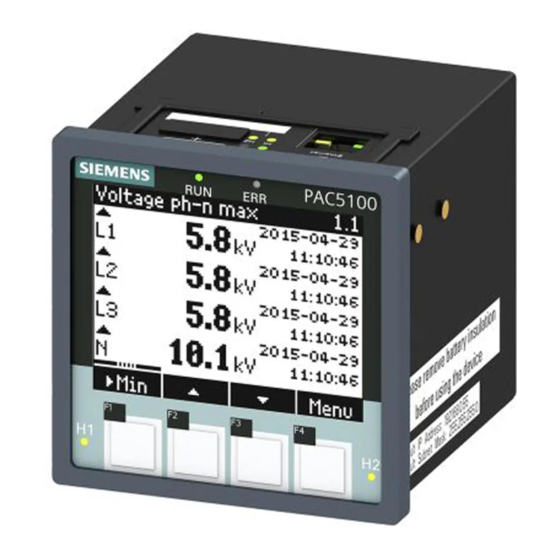
Page 23: Display And Softkeys
3 Device Design 3.2 Display and Softkeys Display and Softkeys Display The layout of the display is shown in the following figure. Title Voltage ph-n MAX 230.00 V Date/Time 231.00 V Date/Time Display area 229.00 V Date/Time 2.00 V Date/Time ... -
Page 24: Electrical Design
3 Device Design 3.3 Electrical Design Electrical Design SENTRON PAC5100/5200 contains the following electrical modules: • Digital signal processor (DSP) • Display and Softkeys (optional) • 4 inputs for alternating voltage measurements • 3 inputs for alternating current measurements • 2 binary outputs •... -
Page 25: Measurands And Recording
Measurands and Recording Measuring and Recording System Measurands Display of Measurands SENTRON PAC5100/5200, 7KM5212/5412, Device Manual E50417-H1040-C568-A1, Edition 03.2015... -
Page 26: Measuring And Recording System
RTC 10-minute limit. Subsequently, the values for the 10-/12-period time intervals are aggregated over additional time intervals (for example, 10-minute interval at SENTRON PAC5200). 10-Minute Interval (SENTRON PAC5200) The value aggregated in a 10-minute interval is tagged with the absolute time (for example 01:10:00). The time at the end of the aggregation interval is indicated as the time qualifier. - Page 27 4 Measurands and Recording 4.1 Measuring and Recording System Flagging Concept During conditions of undervoltage, overvoltage, or voltage interruption, the measurement method can return implausible values for other measurands (for example, frequency measurement, voltage harmonics). The flagging concept therefore prevents an individual event from being accounted for multiple times in different measurands (for example, a single undervoltage event both as undervoltage and simultaneously as a frequency change).
- Page 28 4 Measurands and Recording 4.1 Measuring and Recording System Definition of the Measurands Mains Voltage Level • The measurement determines the RMS value of the mains voltage over a 10-period time interval for 50- Hz distribution systems and over a 12-period time interval for 60-Hz distribution systems. All 10-/12-period time intervals are measured without interruption and overlapping (the overlapping area excluded, see Figure 4-1).
- Page 29 4 Measurands and Recording 4.1 Measuring and Recording System Overvoltage of the Mains Voltage • The basic measurement of the RMS value V of overvoltage is the determination of the RMS value (1/2) for each single measuring channel. The limiting value for overvoltages is a percentage value of Udin.
- Page 30 4 Measurands and Recording 4.1 Measuring and Recording System Flicker • The short-term flicker value Pst and long-term flicker value Plt are determined for phase-to-ground volt- ages and delta voltages. The flicker measurement is performed according to EN 61000-4-15. • The flicker measurement is performed on all 3 voltage channels.
-
Page 31: Recording Of Measurands And Events In Sentron Pac5200
4 Measurands and Recording 4.1 Measuring and Recording System 4.1.2 Recording of Measurands and Events in SENTRON PAC5200 4.1.2.1 Recorder Types SENTRON PAC5200 provides various recording options to monitor and analyze the power quality. Table 4-2 Recording Measured Values Recording Measurands... - Page 32 4 Measurands and Recording 4.1 Measuring and Recording System The interaction of the recorders is depicted in the following figure: Measurand V(t) Pst, Plt Flicker meter Recorder V(t) A/ D Converter I (t) Frequency Measurand Recorder Event PQ events: Interruptions , Swells Recorder (½) Dips...
- Page 33 4 Measurands and Recording 4.1 Measuring and Recording System 4.1.2.2 Measurement Recorder In addition to measured values used to determine the power quality, the Measurement recorder also records a number of other measured values (for example min/max values). Recording of the following measurands can be parameterized via the user interface: •...
- Page 34 4 Measurands and Recording 4.1 Measuring and Recording System 4.1.2.3 Trend Recorder The trend recorder ensures the acquisition and long-term monitoring of the voltage V (1/2) during voltage changes. If a change of the measured value compared to the RMS value recorded last occurs during the parameterized measuring interval, which exceeds or falls below the tolerance limit, this new RMS value will be recorded.
- Page 35 4 Measurands and Recording 4.1 Measuring and Recording System 4.1.2.4 Event Recorder The Event Recorder exclusively records PQ events (undervoltage, overvoltage, voltage interruptions). The use nominal voltage is the reference value for the analysis. rated Voltage swell Hysteresis (2 %) Voltage dip Hysteresis (2%)
- Page 36 4 Measurands and Recording 4.1 Measuring and Recording System 4.1.2.5 Fault Recorder After a trigger has been activated, the fault recorder records the sampled values of voltage curves and/or cur- rent curves. A trigger is activated when a measured value exceeds or falls short of a parameterized threshold value.
- Page 37 4 Measurands and Recording 4.1 Measuring and Recording System You can set the following parameters on the user interface: • recording the voltage and/or current • activation/deactivation of the fault recorder triggering • tolerance unit: in percent or numerical • lower threshold value, referred to U or I rated...
- Page 38 4.1.2.6 Storing and Transmitting Recorder Data in SENTRON PAC5200 Data Storage SENTRON PAC5200 features an internal 2-GB data storage for storing the recorder data. You can manually parameterize the data volume that can be stored for each recorder from 0 % to 100 %: •...
-
Page 39: Measurands
Active power factor cos : cos (a) • Power factor PF: PFa • Phase angle : a • Frequency (system frequency): f • Flicker (only SENTRON PAC5200): Pst, Plt Harmonics • Fundamental V • Harmonics V, magnitude: H_Va-x • Fundamental I •... -
Page 40: Measurands In 3-Wire And 4-Wire Networks
Power factor PF: PFa, PFb, PFc, PF • Phase angle : a, b, c, • Frequency (power frequency): f (see Table 4-17) • Flicker (only SENTRON PAC5200): Pst, Plt Harmonics • Fundamental V • Harmonics V, magnitude: H_Va-x, H_Vb-x, H_Vc-x •... -
Page 41: Measurands Depending On The Connection Type
4 Measurands and Recording 4.2 Measurands 4.2.3 Measurands Depending on the Connection Type 4.2.3.1 Operational Measurands and Connection Types Table 4-3 Operational Measurands, Connection Types in Power Systems Measurand Circuit 1-phase 3-wire Network 4-wire Network (x = 1 to 40) System (Delta) (Star) - Page 42 4 Measurands and Recording 4.2 Measurands Table 4-3 Operational Measurands, Connection Types in Power Systems (cont.) Measurand Circuit 1-phase 3-wire Network 4-wire Network (x = 1 to 40) System (Delta) (Star) Balanced Unbal- Unbal- Balanced Unbal- (1I) anced (3I) anced (2I) (1I) anced (3I) cos (b)
- Page 43 4 Measurands and Recording 4.2 Measurands Table 4-3 Operational Measurands, Connection Types in Power Systems (cont.) Measurand Circuit 1-phase 3-wire Network 4-wire Network (x = 1 to 40) System (Delta) (Star) Balanced Unbal- Unbal- Balanced Unbal- (1I) anced (3I) anced (2I) (1I) anced (3I) Plt_b-N...
- Page 44 4 Measurands and Recording 4.2 Measurands 4.2.3.2 Harmonics, Connection Types Table 4-4 Harmonics, Connection Types in Power Systems Measurand Circuit 1-phase 3-wire Networ 4-wire Network (x = 1 to 40) System (Delta) (Star) Balanced Unbal- Unbal- Balanced Unbal- (1I) anced (3I) anced (2I) (1I) anced (3I)
- Page 45 4 Measurands and Recording 4.2 Measurands 4.2.3.3 Measurands of Power, Connection Types Table 4-5 Measurands of Power, Connection Types in Power Systems Measurand Circuit 1-phase 3-wire Network 4-wire Network System (Delta) (Star) Balanced Unbal- Unbal- Balanced Unbal- (1I) anced (3I) anced (2I) (1I) anced...
- Page 46 4 Measurands and Recording 4.2 Measurands 4.2.3.4 Measurands of Energy, Connection Types Table 4-6 Measurands of Energy, Connection Types in Power Systems Measur- Circuit 1-phase 3-wire Network 4-wire Network Inter- System (Delta) (Star) vals (Cycle) Balanced Unbal- Unbal- Balanced Unbal- (1I) anced (3I) anced (2I)
- Page 47 4 Measurands and Recording 4.2 Measurands Table 4-6 Measurands of Energy, Connection Types in Power Systems (cont.) Measur- Circuit 1-phase 3-wire Network 4-wire Network Inter- System (Delta) (Star) vals (Cycle) Balanced Unbal- Unbal- Balanced Unbal- (1I) anced (3I) anced (2I) (1I) anced (3I) Reactive Energy - Capacitive...
-
Page 48: Data Availability For Sentron Pac5100
4 Measurands and Recording 4.2 Measurands 4.2.4 Data Availability for SENTRON PAC5100 4.2.4.1 Data Availability of the Operational Measurands for SENTRON PAC5100 Table 4-7 Data Availability of the Operational Measurands for SENTRON PAC5100 Limit violation HTML and Display Operational Measurands (Mean Value) Measurand Interface/Protocol... - Page 49 4 Measurands and Recording 4.2 Measurands Table 4-7 Data Availability of the Operational Measurands for SENTRON PAC5100 (cont.) Limit violation HTML and Display Operational Measurands (Mean Value) Measurand Interface/Protocol (x = 1 to 40) Ethernet/Modbus TCP 10/12 cycle 10/12 cycle 10/12 cycle cos (c) cos ...
- Page 50 4 Measurands and Recording 4.2 Measurands Table 4-7 Data Availability of the Operational Measurands for SENTRON PAC5100 (cont.) Limit violation HTML and Display Operational Measurands (Mean Value) Measurand Interface/Protocol (x = 1 to 40) Ethernet/Modbus TCP 10/12 cycle 10/12 cycle 10/12 cycle THDS_Vb THDS_Vc...
- Page 51 4 Measurands and Recording 4.2 Measurands 4.2.4.2 Data Availability of the Measurands of Power for SENTRON PAC5100 Table 4-8 Data Availability of the Measurands of Power for SENTRON PAC5100 Limit violation HTML and Display Operational Measurands (Mean Value) Interface/Protocol Measurand Ethernet/Modbus TCP 10/12 cycle 10/12 cycle...
- Page 52 4 Measurands and Recording 4.2 Measurands 4.2.4.3 Data Availability of the Measurands of Energy for SENTRON PAC5100 Table 4-9 Data Availability of the Measurands of Energy for SENTRON PAC5100 Limit violation HTML and Display Operational Measurands (Mean Value) Interface/Protocol Measurand Ethernet/Modbus TCP 10/12 cycle 10/12 cycle...
- Page 53 4 Measurands and Recording 4.2 Measurands Table 4-9 Data Availability of the Measurands of Energy for SENTRON PAC5100 (cont.) Limit violation HTML and Display Operational Measurands (Mean Value) Interface/Protocol Measurand Ethernet/Modbus TCP 10/12 cycle 10/12 cycle 10/12 cycle SENTRON PAC5100/5200, 7KM5212/5412, Device Manual E50417-H1040-C568-A1, Edition 03.2015...
-
Page 54: Data Availability For Sentron Pac5200
4 Measurands and Recording 4.2 Measurands 4.2.5 Data Availability for SENTRON PAC5200 4.2.5.1 Data Availability of the Operational Measurands for SENTRON PAC5200 Table 4-10 Data Availability of the Operational Measurands for SENTRON PAC5200 Limit violation HTML and Display Operational Measurands... - Page 55 4 Measurands and Recording 4.2 Measurands Table 4-10 Data Availability of the Operational Measurands for SENTRON PAC5200 (cont.) Limit violation HTML and Display Operational Measurands (Mean Value) Measurand Interface/Protocol (x = 1 to 40) Ethernet/Modbus TCP 10/12 cycle 10/12 cycle 10/12 cycle cos (c)
- Page 56 4 Measurands and Recording 4.2 Measurands Table 4-10 Data Availability of the Operational Measurands for SENTRON PAC5200 (cont.) Limit violation HTML and Display Operational Measurands (Mean Value) Measurand Interface/Protocol (x = 1 to 40) Ethernet/Modbus TCP 10/12 cycle 10/12 cycle...
- Page 57 4 Measurands and Recording 4.2 Measurands 4.2.5.2 Data Availability of the Measurands of Power for SENTRON PAC5200 Table 4-11 Data Availability of the Measurands of Power for SENTRON PAC5200 Limit violation HTML and Display Operational Measurands (Mean Value) Interface/Protocol Measurand...
- Page 58 4 Measurands and Recording 4.2 Measurands 4.2.5.3 Data Availability of the Measurands of Energy for SENTRON PAC5200 Table 4-12 Data Availability of the Measurands of Energy for SENTRON PAC5200 Limit violation HTML and Display Operational Measurands (Mean Value) Interface/Protocol Measurand...
- Page 59 4 Measurands and Recording 4.2 Measurands Table 4-12 Data Availability of the Measurands of Energy for SENTRON PAC5200 (cont.) Limit violation HTML and Display Operational Measurands (Mean Value) Interface/Protocol Measurand Ethernet/Modbus TCP 10/12 cycle 10/12 cycle 10/12 cycle SENTRON PAC5100/5200, 7KM5212/5412, Device Manual...
- Page 60 4 Measurands and Recording 4.2 Measurands 4.2.5.4 Recording and Evaluation of the Operational Measurands of SENTRON PAC5200 Table 4-13 Recording and Evaluation of the Operational Measurands of SENTRON PAC5200 Event Fault Trend Measurement Recorder Recorder Recorder Recorder Measurand (x = 1 to 40) Max.
- Page 61 4 Measurands and Recording 4.2 Measurands Table 4-13 Recording and Evaluation of the Operational Measurands of SENTRON PAC5200 (cont.) Event Fault Trend Measurement Recorder Recorder Recorder Recorder Measurand (x = 1 to 40) Max. Value Min. Value Values COMTRADE PQDIF cos (c)
- Page 62 4 Measurands and Recording 4.2 Measurands Table 4-13 Recording and Evaluation of the Operational Measurands of SENTRON PAC5200 (cont.) Event Fault Trend Measurement Recorder Recorder Recorder Recorder Measurand (x = 1 to 40) Max. Value Min. Value Values COMTRADE PQDIF...
- Page 63 4 Measurands and Recording 4.2 Measurands 4.2.5.5 Recording and Evaluation of the Power Types of SENTRON PAC5200 Table 4-14 Recording and Evaluation of the Power Types of SENTRON PAC5200 Measurement Recorder Measurand Max. Value Min. Value Active Power Reactive Power...
-
Page 64: Display Of Measurands
60 Hz (±9 Hz) 51.0 Hz to 69.0 Hz (see Table 4-17) Flicker Pst, Plt Pst, Plt: 0,4 to 4 Acc. to class S, (only SENTRON PAC5200) Pinst: 0 to 40 IEC 61000-4-30: Pst: ±10 % Plt: ±10 % Pinst: ±16 %... -
Page 65: Measurands And Operational Measurement Accuracy Acc. To Iec 61557-12
4 Measurands and Recording 4.3 Display of Measurands 4.3.2 Measurands and Operational Measurement Accuracy acc. to IEC 61557-12 Table 4-16 Measurands and their Operational Measurement Accuracy Measurands Unit Rated Value Measurement Accuracy Class Range Current I AC 1 A 20 % to 200 % I rated Acc. -
Page 66: Accuracy Of The Frequency Measurement
4 Measurands and Recording 4.3 Display of Measurands 4.3.3 Accuracy of the Frequency Measurement Table 4-17 Accuracy of the Frequency Measurement Circuit Accuracy Voltage to V 0 % to 15 % V invalid rated 15 % to 30 % V : 40 mHz rated 30 % to 120 % V... -
Page 67: Getting Started
Getting Started Unpacking, Inspecting the Delivery, and Installing the Battery Assembly Electrical Connection System Requirements Access Rights Meaning of the LEDs Commissioning SENTRON PAC5100/5200, 7KM5212/5412, Device Manual E50417-H1040-C568-A1, Edition 03.2015... -
Page 68: Unpacking, Inspecting The Delivery, And Installing The Battery
5 Getting Started 5.1 Unpacking, Inspecting the Delivery, and Installing the Battery Unpacking, Inspecting the Delivery, and Installing the Battery Unpacking The SENTRON PAC5100/5200 has been safely packed for transport in the factory. Unpack the device with care and do not use force. Use an appropriate tool if necessary. After unpacking, inspect the device visually for any mechanical defects. - Page 69 5 Getting Started 5.1 Unpacking, Inspecting the Delivery, and Installing the Battery ✧ Take the wrapped battery out of the battery compartment. ✧ Remove the plastic foil from the battery. ✧ Insert the battery into the battery compartment with the polarity imprinted on the top side of the device (see Figure 5-1).
- Page 70 5 Getting Started 5.1 Unpacking, Inspecting the Delivery, and Installing the Battery NOTE on Battery Disposal The battery used in this device contains lithium. It may only be replaced by qualified personnel and disposed of by authorized recycling companies. Do not dispose of the battery in the regular household waste. The national and international regulations must be observed when disposing of the battery.
-
Page 71: Assembly
5 Getting Started 5.2 Assembly Assembly 5.2.1 General Assembly Notes Depending on the model, SENTRON PAC5100/5200 is designed either for panel flush mounting (device with display) or for DIN rail assembly (device without display). WARNING Do not touch any live parts. Non-observance may lead to death or serious injury. -
Page 72: Assembly
5 Getting Started 5.2 Assembly 5.2.2 Assembly Devices with Display for Panel Flush Mounting To install the device into a switch panel, proceed as follows: ✧ Push the device in installation position into the cut-out of the switch panel and hold the device tight. ✧... - Page 73 5 Getting Started 5.2 Assembly Devices without Display for DIN Rail Mounting To mount the device on a DIN rail, proceed as follows: Snap-on clip Guiding of the snap-on clip DIN rail Release device Pulling direction Figure 5-3 Assembly of the DIN Rail Device ✧...
-
Page 74: Electrical Connection
✧ Check the polarity and the phase assignment at the instrument transformers. Siemens recommends leaving the device for a minimum of 2 hours in the operating room, before using it to allow temperature equalization and to avoid dimness and condensation. -
Page 75: Electrical Connection Of Sentron Pac5100/5200
5 Getting Started 5.3 Electrical Connection 5.3.2 Electrical Connection of SENTRON PAC5100/5200 NOTE The electrical terminal connections of the device models are identical. Terminal connection of the supply voltage Figure 5-4 Terminal Connection of the Supply Voltage at the SENTRON PAC5100/5200 DANGER Hazard due to high voltage Non-observance will lead to death or serious injury. -
Page 76: System Requirements
5 Getting Started 5.4 System Requirements Connect the cables of the supply voltage on the terminal side of the device at terminal block H as follows: Supply from the Alternating Voltage System Terminal N/-: Neutral conductor of the supply voltage Terminal L/+: Phase of the supply voltage Terminal... -
Page 77: Access Rights
5 Getting Started 5.5 Access Rights Access Rights Access Rights for Configuration and Maintenance To determine access rights, you have to set up passwords when configuring the device. You have to specify an activation password and a maintenance password; chapter 7.3.6.3 describes how to set up passwords. The activation password is required to enable parameter changes in the device. -
Page 78: Meaning Of The Leds
5 Getting Started 5.6 Meaning of the LEDs Meaning of the LEDs 7KM5212/5412 automatically monitors the functions of its hardware and software components. The LEDs on the top side of the housing indicate the current device status. ERROR Link/Activity Speed Figure 5-5 Designation of the LEDs Depending on the status, the LEDs can be permanently on, flashing, or off. -
Page 79: Commissioning
5 Getting Started 5.7 Commissioning Commissioning 5.7.1 Initial Commissioning DANGER Hazard due to high voltage Non-observance will lead to death or serious injury. Work may only be carried out by trained personnel (see Preface) who are familiar with and observe the safety requirements and precautions. -
Page 80: Changes During Operation
5 Getting Started 5.7 Commissioning ✧ Switch on the supply voltage of the device. NOTE The device does not have a power on/off switch. Switch the supply voltage on or off directly at the respective supply cable. After an operating time of approximately 15 minutes, the device will stay within the tolerances specified in the technical data. -
Page 81: Starting The Device With The Default Ip Address
5 Getting Started 5.7 Commissioning 5.7.3 Starting the Device with the Default IP Address SENTRON PAC5100/5200 has the following internal default IP address: 192.168.0.55. If you have entered a custom IP address during device configuration, you can temporarily activate the internal default IP address of the device if necessary. - Page 82 5 Getting Started 5.7 Commissioning DIN Rail Devices ✧ Press the IP-Addr. push-button on the DIN Rail Site for at least 3 s. IP-Addr. push-button for default IP address Default IP Address : 192.168.0.55 Default Subnet Mask : 255.255 .255.0 Figure 5-7 Location of the Push-button for Activating the Default IP Address When you press the IP-Addr.
-
Page 83: Connection Principle
Connection Principle Terminals Ethernet Interface Connection Types and Connection Examples SENTRON PAC5100/5200, 7KM5212/5412, Device Manual E50417-H1040-C568-A1, Edition 03.2015... -
Page 84: Terminals
6 Connection Principle 6.1 Terminals Terminals The terminals on the terminal side of the device are designed as terminal blocks: Figure 6-1 Terminal Blocks on the Terminal Side of the SENTRON PAC5100/5200 SENTRON PAC5100/5200 has the following terminal blocks: Table 6-1 Terminal Blocks at SENTRON PAC5100/5200 Terminal Block Description... - Page 85 6 Connection Principle 6.1 Terminals Functions of the Terminals at SENTRON PAC5100/5200 Table 6-2 Functions of the Terminals Terminal Assigned Function, Description Measured Value or Indication => E: I Conductor a, input, current measurement <= E: I Conductor a, output, current measurement =>...
-
Page 86: Ethernet Interface
Ethernet Interface Z (Detail of the Top Side) NOTE If you do not connect a cable to the RJ45 socket, Siemens recommends to cover the socket with a cap or dum- my plug (not included in the delivery) to prevent the contacts from becoming dirty. -
Page 87: Connection Types And Connection Examples
6 Connection Principle 6.3 Connection Types and Connection Examples Connection Types and Connection Examples 6.3.1 Using SENTRON PAC5100/5200 in the Power Systems IT, TT, and TN When using SENTRON PAC5100/5200 in the power systems IT, TT, and TN, no special operating conditions must be observed. - Page 88 6 Connection Principle 6.3 Connection Types and Connection Examples Example 1-phase System, No Voltage Transformer Terminals SENTRON PAC5100/5200 10 A Figure 6-3 Example 1-phase System, No Voltage Transformer Example 3-wire Network, 2 Voltage Transformers and 1 Current Transformer, Balanced Terminals SENTRON PAC5100/5200 10 A 10 A 10 A...
- Page 89 6 Connection Principle 6.3 Connection Types and Connection Examples Example 3-wire Network, No Voltage Transformer, 3 Current Transformers, Unbalanced Terminals SENTRON PAC5100/5200 resp. 10 A Figure 6-5 Example 3-wire Network, No Voltage Transformer, 3 Current Transformers, Unbalanced Example 3-wire Network, No Voltage Transformer, 2 Current Transformers, Unbalanced Terminals SENTRON PAC5100/5200 resp.
- Page 90 6 Connection Principle 6.3 Connection Types and Connection Examples Example 3-wire Network, 2 Voltage Transformers and 2 Current Transformers, Unbalanced Terminals SENTRON PAC5100/5200 10 A 10 A 10 A Figure 6-7 Example 3-wire Network, 2 Voltage Transformers and 2 Current Transformers, Unbalanced NOTICE The secondary voltage on terminal F (voltage) must not exceed AC 480 V (AC 347 V for UL conditions).
- Page 91 6 Connection Principle 6.3 Connection Types and Connection Examples Example 3-wire Network, 2 Voltage Transformers and 3 Current Transformers, Unbalanced Terminals SENTRON PAC5100/5200 10 A 10 A 10 A Figure 6-8 Example 3-wire Network, 2 Voltage Transformers and 3 Current Transformers, Unbalanced NOTICE The secondary voltage on terminal F (voltage) must not exceed AC 480 V (AC 347 V for UL conditions).
- Page 92 6 Connection Principle 6.3 Connection Types and Connection Examples Example 4-wire Network, 1 Voltage Transformer and 1 Current Transformer, Balanced Terminals SENTRON PAC5100/5200 10 A Figure 6-9 Example 4-wire Network, 1 Voltage Transformer and 1 Current Transformer, Balanced Example 4-wire Network, No Voltage Transformer, 3 Current Transformers, Unbalanced Terminals SENTRON PAC5100/5200 resp.
- Page 93 6 Connection Principle 6.3 Connection Types and Connection Examples Example 4-wire Network, 3 Voltage Transformers and 3 Current Transformers, Unbalanced Terminals SENTRON PAC5100/5200 resp. 10 A Figure 6-11 Example 4-wire Network, 3 Voltage Transformers and 3 Current Transformers, Unbalanced SENTRON PAC5100/5200, 7KM5212/5412, Device Manual E50417-H1040-C568-A1, Edition 03.2015...
-
Page 94: Example - Special Application
6 Connection Principle 6.3 Connection Types and Connection Examples 6.3.4 Example - Special Application Example 3-wire Network, 3 Voltage Transformers and 3 Current Transformers, Unbalanced Terminals SENTRON PAC5100/5200 resp. 10 A Figure 6-12 Example 3-wire Network, 3 Voltage Transformers and 3 Current Transformers, Unbalanced SENTRON PAC5100/5200, 7KM5212/5412, Device Manual E50417-H1040-C568-A1, Edition 03.2015... -
Page 95: Operation At Use Of A Pc
Operation at Use of a PC General Usage Notes Start and Design of the User Interface Configuration of the Device Value View and Evaluation Maintenance Example of a Parameterization and Measured Value Evaluation for SENTRON PAC5200 SENTRON PAC5100/5200, 7KM5212/5412, Device Manual E50417-H1040-C568-A1, Edition 03.2015... -
Page 96: General Usage Notes
7 Operation at Use of a PC 7.1 General Usage Notes General Usage Notes All SENTRON PAC5100/5200 device models can be operated via the HTML pages from the connected PC. Devices with a display can additionally be operated using the softkeys on the display side. This chapter describes the PC-based operation;... -
Page 97: Start And Design Of The User Interface
7 Operation at Use of a PC 7.2 Start and Design of the User Interface Start and Design of the User Interface 7.2.1 Initial Start of the Operation Before starting the user interface, the following preconditions must be satisfied: ✧ Assemble the SENTRON PAC5100/5200 as described in Assembly. -
Page 98: Enabling Javascript
7 Operation at Use of a PC 7.2 Start and Design of the User Interface NOTE When starting the device for the first time, a set of parameters with factory settings is loaded. You can modify these settings during the parameterization (see Configuration of the Device). To set a different user language for the user interface, open the Administrative menu on the Configure tab, select the Device and language menu item and change the language as described in Device and Language. -
Page 99: Number Of Connections Via Html
7 Operation at Use of a PC 7.2 Start and Design of the User Interface ✧ In the window of the Security tab, select the Internet icon. ✧ On the Security tab, scroll to Medium by moving the scroll bar with your mouse. Alternatively, if there is no scroll bar, click Default Level and set the scroll bar that appears to Medium. -
Page 100: Layout Of The User Interface
7 Operation at Use of a PC 7.2 Start and Design of the User Interface 7.2.4 Layout of the User Interface The user interface has the following layout: Microsoft Internet Explorer Address bar Online help Menu bar Navigation bar Toolbar Navigation window Element Menu... -
Page 101: Starting The User Interface During Operation
7 Operation at Use of a PC 7.2 Start and Design of the User Interface 7.2.5 Starting the User Interface during Operation Starting the User Interface To start the user interface, proceed as follows: ✧ Start Microsoft Internet Explorer. ✧ Enter the IP address in Microsoft Internet Explorer (for example the default IP address: 192.168.0.55) of SENTRON PAC5100/5200 and press ENTER. - Page 102 7 Operation at Use of a PC 7.2 Start and Design of the User Interface 7.2.5.1 Show Device Information ✧ Click the Show device information item in the navigation window. The Show device information input/output window shows the following information (see figure 7-4): ...
- Page 103 7 Operation at Use of a PC 7.2 Start and Design of the User Interface Save As ✧ Select in the button choice Open/Save/Cancel Save Save As: Figure 7-7 Save As Dialog ✧ Select the file path. ✧ Use the file name suggested in the File name: list box or enter a new file name with the file extension .TXT.
- Page 104 7 Operation at Use of a PC 7.2 Start and Design of the User Interface 7.2.5.3 Message Logs Menu The Message Logs menu contains operational indications and error messages registered and saved by the device during operation. The device can save up to 128 operational indications and up to 128 error messages. When the storage capacity is exceeded, the oldest indications will be overwritten successively.
- Page 105 7 Operation at Use of a PC 7.2 Start and Design of the User Interface Error Log NOTE The information about error messages described below is intended for service purposes. Inform the customer service about this information when there are problems with your device. To display the error messages, proceed as follows: ✧...
-
Page 106: Configuration Of The Device
7 Operation at Use of a PC 7.3 Configuration of the Device Configuration of the Device NOTE The device contains two sets of parameters. The set of parameters currently used for device operations is the active set of parameters. The inactive set of parameters is called the passive set of parameters. The following sections describe how to change and enable the passive set of parameters. - Page 107 7 Operation at Use of a PC 7.3 Configuration of the Device NOTE If you have selected Get device configuration, an editable copy of the active parameter set of the device is displayed on the screen. In the meantime, the active parameter set in the device continues to operate. If you have selected Open configuration from file, you can open and enable or edit the copy of a parameter set that was already created and saved to a folder.
- Page 108 7 Operation at Use of a PC 7.3 Configuration of the Device Get Default Configuration and Editing ✧ Click Get default configuration. A copy of the factory settings (= passive set of parameters) of the device is opened for editing. NOTE You can edit the displayed factory settings, activate and use them as active set of parameters.
- Page 109 7 Operation at Use of a PC 7.3 Configuration of the Device The Choose file dialog opens. Figure 7-13 Choose File ✧ Select the desired file (extension .cfg) in the directory. NOTE You can open only files with the following properties of the file name: •...
- Page 110 7 Operation at Use of a PC 7.3 Configuration of the Device 7.3.1.3 Finish Configuration When you have changed the configuration, you must either enable it as the active set of parameters or save it. Activating the Set of Parameters To activate the set of parameters, proceed as follows: ✧...
- Page 111 7 Operation at Use of a PC 7.3 Configuration of the Device Save Configuration to File You can save both the active and the passive configuration to a file. Proceed as follows: ✧ In the navigation window, select the Finish configuration menu and click Save Configuration to File. Figure 7-15 Configure Tab, Save Configuration to File Input/Output Window ✧...
- Page 112 7 Operation at Use of a PC 7.3 Configuration of the Device Save As ✧ Select in the button choice Open/Save/Cancel Save Save As: Figure 7-17 Save As Dialog ✧ Select the file path. ✧ Use the file name suggested in the File name: list box or enter a new file name with the file extension *.CFG.
- Page 113 7 Operation at Use of a PC 7.3 Configuration of the Device Cancel To cancel the configuration, proceed as follows: ✧ In the navigation window, select the Finish configuration menu and click Cancel. Figure 7-18 Configure Tab, Cancel Input/Output Window ✧...
-
Page 114: Access To The Passive Set Of Parameters By Multiple Users
7 Operation at Use of a PC 7.3 Configuration of the Device 7.3.2 Access to the Passive Set of Parameters by Multiple Users Reading the Passive Set of Parameters The user interface allows the simultaneous read access of up to 3 web servers to the passive set of parameters. Editing the Passive Set of Parameters The passive set of parameters can only be edited from one computer or notebook even though multiple users have simultaneous read access. -
Page 115: Setting The Operational Parameters
7 Operation at Use of a PC 7.3 Configuration of the Device 7.3.3 Setting the Operational Parameters In the Configure tab you can view and edit the set operational parameters. You can select the parameters in the Operational menu in the navigation window. The submenus Process connections, Select automation function, HMI, PQ Management and Administrative are available for making the settings. - Page 116 7 Operation at Use of a PC 7.3 Configuration of the Device 7.3.3.1 Process Connections 7.3.3.1.1 AC Measurement Default Settings and Setting Ranges of Measured-value Acquisition NOTE When setting the parameters, make sure that the set values are not contradictory. In the case of contradictory parameter settings, Primary nominal voltage is indicated as faulty (red) and Net- work type as not adjustable (gray).
- Page 117 7 Operation at Use of a PC 7.3 Configuration of the Device To change the parameters of the measured-value acquisition, proceed as follows: ✧ In the navigation window, select the Operational menu, then the Process connections submenu and click AC measurement. Figure 7-20 Configure Tab, AC Measurement Input/Output Window ✧...
- Page 118 7 Operation at Use of a PC 7.3 Configuration of the Device ✧ If you are not using a voltage transformer and/or current transformer between the measurement object and SENTRON PAC5100/5200, click no in the respective option field. The associated fields for primary and secondary values are hidden in this case.
- Page 119 7 Operation at Use of a PC 7.3 Configuration of the Device 7.3.3.1.2 Binary Outputs Default Settings and Setting Ranges of the Binary Outputs Table 7-4 Settings of Binary Outputs Parameter Default Setting Setting Range Source type Indication Indication Energy counter Source Type Indication Indication -none-...
- Page 120 7 Operation at Use of a PC 7.3 Configuration of the Device To change the outputs of a binary output, proceed as follows: ✧ In the navigation window, select the Operational menu, then the Process connections submenu and click Binary outputs. Figure 7-21 Configure Tab, Binary Outputs Input/Output Window NOTE...
- Page 121 7 Operation at Use of a PC 7.3 Configuration of the Device Parameterizing an Indication ✧ Select the desired parameters for an indication in the list boxes and option fields as described in Table 7-4. NOTE If you select -not assigned- as the source of an indication and/or energy counter, the corresponding binary output is inactive.
- Page 122 7 Operation at Use of a PC 7.3 Configuration of the Device Pulse with retrigger: This indication is output as pulse. The output pulse is retriggered if the indication is changed during the pulse output. This means that the pulse output is extended. Indication Indication Indication...
- Page 123 7 Operation at Use of a PC 7.3 Configuration of the Device 7.3.3.1.3 LEDs Default Settings and Setting Options of the LEDs Table 7-5 LED Settings Default Setting Setting Options Device ready Not settable ERROR -none- Errors are signaled as parameterized (only error indications can be parameterized).
- Page 124 7 Operation at Use of a PC 7.3 Configuration of the Device ✧ Select the desired parameters in the list boxes and option fields as described in Table 7-5. NOTE Select Indication -none- to disable the corresponding LED. ✧ After the parameterization click Send. The parameters are transmitted to the device but not enabled yet (passive set of parameters).
- Page 125 7 Operation at Use of a PC 7.3 Configuration of the Device 7.3.3.2 Automation Functions 7.3.3.2.1 Limit Settings In the Select automation functions menu you can set upper or lower limits for up to 16 measured values. Limit violations of the upper or lower value range can be output as indications. Up to 4 limiting value violations can be signaled at the device via the two binary outputs and the LEDs H1 and H2.
- Page 126 7 Operation at Use of a PC 7.3 Configuration of the Device Parameterizing a Limit To change, for example, limit 1, proceed as follows: ✧ In the navigation window, select the Operational menu, then the Select automation functions submenu and click Measurand limits 1-8. Figure 7-28 Configure Tab, Measurand Limits 1-8 Input/Output Window (Detail) ✧...
- Page 127 7 Operation at Use of a PC 7.3 Configuration of the Device NOTE Which quantities are offered in the Measurand list box depends on the configured network type. The Network type is specified in the Process connections submenu, AC measurement input/output window, see AC Measurement.
- Page 128 7 Operation at Use of a PC 7.3 Configuration of the Device Rule for Linking Indications to a Group Indication In a group indication, up to 4 indications can sequentially be linked logically. The indications 1 to 4 are always linked successively as follows: Indication 1 with Indication 2 = Indication 1/2 Indication 1/2 with Indication 3 = Indication 1/2/3...
- Page 129 7 Operation at Use of a PC 7.3 Configuration of the Device Parameterizing a Group Indication To change, for example, group indication 1, proceed as follows: ✧ In the navigation window, select the Operational parameters menu, then the Select automation functions submenu and click Group indications 1-4.
-
Page 130: Hmi
7 Operation at Use of a PC 7.3 Configuration of the Device 7.3.4 7.3.4.1 Display Settings Default Settings and Setting Ranges Table 7-8 Display Settings Parameter Default Setting Setting Range Contrast 0 to 10 Time until dimmed 0 min to 99 min Refresh time 1000 330 ms to 3000 ms... - Page 131 7 Operation at Use of a PC 7.3 Configuration of the Device ✧ Enter the desired values into the fields and select the corresponding parameters in the option fields as described in Table 7-8. ✧ After the parameterization click Send. The parameters are transmitted to the device but not enabled yet (passive set of parameters).
- Page 132 7 Operation at Use of a PC 7.3 Configuration of the Device 7.3.4.2 User Defined Screens In the User defined screen menu you can parameterize up to 4 different User screens. Each Screen type allows you to select whether to display the measured values numerically (2 or 4 measured values) or graphically and numerically (2 or 3 measured values).
- Page 133 7 Operation at Use of a PC 7.3 Configuration of the Device To change the User define screens, proceed as follows: ✧ In the navigation window, select the HMI menu and click User Define Screen. Figure 7-34 Configure Tab, User Define Screen Input/Output Window ✧...
-
Page 134: Recording And Reporting
7 Operation at Use of a PC 7.3 Configuration of the Device 7.3.5 Recording and Reporting 7.3.5.1 Event Recorders Default Settings and Setting Ranges Table 7-10 Event Recorders Parameter Default Setting Setting Range Supply voltage Swell threshold 110 % 105 % to 140 % in 5-% steps Dip threshold 90 % 75 % to 95 % in 5-% steps... - Page 135 7 Operation at Use of a PC 7.3 Configuration of the Device To change the Event Recorders, proceed as follows: ✧ In the navigation window, select the Recording and Reporting menu and click Event Recorders. Figure 7-35 Configure Tab, Event Recorders Input/Output Window ✧...
- Page 136 7 Operation at Use of a PC 7.3 Configuration of the Device 7.3.5.2 Trigger Management Default Settings and Setting Ranges Table 7-11 Trigger Management Parameter Default Setting Setting Range Voltage trigger limits Trigger active Tolerance unit Percentage Percentage Numerical Lower threshold 90.00 % 0.00 % to 99.99 % of the of the primary of the primary nominal...
- Page 137 7 Operation at Use of a PC 7.3 Configuration of the Device To change the trigger management settings, proceed as follows: ✧ In the navigation window, select the Recording and Reporting menu and click Trigger management. Figure 7-36 Configure Tab, Trigger Management Input/Output Window ✧...
- Page 138 7 Operation at Use of a PC 7.3 Configuration of the Device 7.3.5.3 Recorder Parameters Default Settings and Setting Ranges Table 7-12 Recorder Management Parameter Default Setting Setting Range Measurement Recorder Average intervals - Frequency 10 s fixed Short term flicker 10 min fixed Long term flicker...
- Page 139 3P3W (3 phases/3 wires): only phase-to-phase voltage NOTE Siemens recommends selecting the PQDIF setting from the Recorded file type list box. When selecting All or CSV, the internal memory will be full prematurely if the CSV file becomes very large compared to the PQDIF file.
- Page 140 7 Operation at Use of a PC 7.3 Configuration of the Device The Measured Value Recorder Intervals and the PQDIF Files The measurement value recorder is responsible for recording average values, min and max values. The measured values recorder intervals are defined according to the averaging intervals setting. Table 7-13 PQDIF File Interval (measured value recorder) Recording...
- Page 141 7 Operation at Use of a PC 7.3 Configuration of the Device A new file is created after a PQDIF file has been completely recorded. 11:00 11:10 12:00 Time 1) 11:10 a.m. to 12:00 p.m. : 1st PQDIF file 2) 12:00 p.m. to 01:00 p.m. : 2nd PQDIF file …...
- Page 142 7 Operation at Use of a PC 7.3 Configuration of the Device Recording with the Trend Recorder The trend recorder is used for recording the voltage events. This is used for the displaying in webserver. The recording of data points (voltage values with a time stamp) that have exceeded/fallen below the parame- terized tolerance value (fault) and the associated creation of a PQDIF file is determined by two trigger criteria: •...
- Page 143 7 Operation at Use of a PC 7.3 Configuration of the Device 7.3.5.4 Memory Management Default Settings and Setting Ranges Table 7-14 Memory Management Parameter Default Setting Setting Range Splitting Event recorder 1.0 % 1 % to 33 % Measurement recorder 35.0 % 33 % to 65 % (the recording time depends on...
- Page 144 7 Operation at Use of a PC 7.3 Configuration of the Device ✧ In the navigation window, select the Recording and Reporting menu and click Memory management. Figure 7-40 Configure Tab, Storage Input/Output Window ✧ Select the respective parameters in the list boxes according to Table 7-14 and enter the desired values in the associated fields.
- Page 145 7 Operation at Use of a PC 7.3 Configuration of the Device 7.3.5.5 Report Configuration The Report configuration allows you to parameterize the PQ threshold parameters (User defined). You can adjust the process connections to the installation environment and enter different operational settings. Alternatively, you can use the default values according to EN 50160 LV&MV or EN 50160 HV.
- Page 146 7 Operation at Use of a PC 7.3 Configuration of the Device NOTE The factory settings are based on EN 50160. If you have changed the settings, the set parameters are applied after a device restart. Resetting to the factory settings is possible. To change the report configuration, proceed as follows: ✧...
- Page 147 7 Operation at Use of a PC 7.3 Configuration of the Device NOTE Power Quality Report describes the output of the power quality report. 7.3.5.6 Recording Parameters Default Settings and Setting Ranges Table 7-16 Reporting Parameters Parameter Default Setting Setting Range Start record option Start next 10th minute Start next minute...
- Page 148 7 Operation at Use of a PC 7.3 Configuration of the Device ✧ If you do not want to make any additional settings, continue with the Activation of the device configuration according to section Activating the Set of Parameters. If you want to change other settings, enter the changes and then enable the device configuration as described in section Activating the Set of Parameters.
-
Page 149: Setting Administrative Parameters
7 Operation at Use of a PC 7.3 Configuration of the Device 7.3.6 Setting Administrative Parameters In the Configure tab you can view and if necessary edit the administrative settings. You can select the parameters in the Administrative menu in the navigation window. These parameters can be changed in the input/output windows Time synchronization, Communication Ethernet and Device and language. - Page 150 7 Operation at Use of a PC 7.3 Configuration of the Device To change the time synchronization, proceed as follows: ✧ In the navigation window, select the Administrative menu and click Time synchronization. Figure 7-43 Configure Tab, Time Synchronization Input/Output Window, Ethernet NTP Selected ✧...
- Page 151 7 Operation at Use of a PC 7.3 Configuration of the Device 7.3.6.2 Communication Ethernet Default Settings and Setting Ranges of the Communication Ethernet Table 7-18 Communication Ethernet Settings Parameter Default Setting Setting Range IP address 192.168.0.55 0.0.0.0 = DHCP Subnet mask 255.255.255.0 Default gateway...
- Page 152 7 Operation at Use of a PC 7.3 Configuration of the Device To change the Ethernet communication settings, proceed as follows: ✧ In the navigation window, select the Administrative menu and click Communication Ethernet. The Communication Ethernet input/output window with Protocol Modbus TCP opens. Figure 7-44 Configure Tab, Communication Ethernet via Modbus TCP Input/Output Window ✧...
- Page 153 7 Operation at Use of a PC 7.3 Configuration of the Device The Open/Save/Cancel button choice opens. Figure 7-45 Open/Save/Cancel Button Choice ✧ Select in the button choice Open/Save/Cancel Save Save As: see figure 7-7. ✧ Select the file path. ✧...
- Page 154 7 Operation at Use of a PC 7.3 Configuration of the Device Ethernet Communication with Bus Protocol Modbus TCP (see figure 7-44) ✧ In the Bus protocol list box select the entry Modbus TCP. ✧ Enter the desired values in the fields and select the parameters in the list boxes and in the option field as described in Table 7-18.
- Page 155 7 Operation at Use of a PC 7.3 Configuration of the Device 7.3.6.3 Device and Language Default Settings and Setting Ranges for Device and Language Table 7-19 Device and Language Settings Parameter Default Setting Setting Range Device name SENTRON_PAC Max. 32 characters Language ENGLISH (US) ENGLISH (US)
- Page 156 7 Operation at Use of a PC 7.3 Configuration of the Device ✧ Select the desired parameters in the list box according to Table 7-19. ✧ Change the passwords if necessary. ✧ After the parameterization click Send. After clicking Send, the parameters are transmitted to the device but not enabled yet (passive set of parameters).
-
Page 157: Value View And Evaluation
7 Operation at Use of a PC 7.4 Value View and Evaluation Value View and Evaluation 7.4.1 Process Connections and Automation Functions The values for Operational parameters (Process connections and Automation functions) are displayed in the Value view and Evaluation tab. To display the values on the screen, proceed as follows: ✧... -
Page 158: Evaluation And Data Management
7 Operation at Use of a PC 7.4 Value View and Evaluation NOTE If *** is displayed instead of a measured value, this measured value is invalid. If ^^^ is displayed instead of a measured value, this measurand is in overflow. To print out the measured values, click the (Print) icon on the toolbar of Microsoft Internet Explorer. - Page 159 7 Operation at Use of a PC 7.4 Value View and Evaluation 7.4.2.1 Events Default Settings and Setting Options Table 7-20Value View and Evaluation - Events Parameter Default Setting Setting Options Event record type Supply Voltage Supply Voltage Frequency Unbalance Start time Current date/time Any with calendar function...
- Page 160 7 Operation at Use of a PC 7.4 Value View and Evaluation Measurement Output as Table ✧ Click Display. The determined results are displayed in a table. In multi-paged tables you can navigate forward and back in the pages using the >> and << buttons. If you want to view a certain page, enter the page at the bottom and click on show.
- Page 161 7 Operation at Use of a PC 7.4 Value View and Evaluation ✧ Click Save. ✧ Close the button choice Download has completed. Open CSV File Alternatively, you can view the event data on the screen and print them if needed. Proceed as follows: ✧...
- Page 162 7 Operation at Use of a PC 7.4 Value View and Evaluation 7.4.2.2 Records Default Settings and Setting Options Table 7-21 Value View and Evaluation - Records Parameter Default Setting Setting Options Record Type Measurement Trend Recorder recorder Measurement recorder Measurement Recorder Start time Current time...
- Page 163 7 Operation at Use of a PC 7.4 Value View and Evaluation Table 7-21 Value View and Evaluation - Records (cont.) Parameter Default Setting Setting Options By time Current time Any with calendar function Start time Time format: depends on date/time format config.
- Page 164 7 Operation at Use of a PC 7.4 Value View and Evaluation Measurement Output as Diagram or Table ✧ If you selected Diagram or Table for Measurement output, click on the Display button. Dependent on the selection, the determined results will be displayed in a table or diagram. In multi-paged tables you can navigate forward and back in the pages using the >>...
- Page 165 7 Operation at Use of a PC 7.4 Value View and Evaluation 7.4.2.3 Power Quality Report Default Settings and Setting Options Table 7-22 Power Quality Report Parameter Default Setting Setting Options Start Time Current time Any with calendar function Time format: depends on date/time format config. End Time Current time Any with calendar function...
- Page 166 7 Operation at Use of a PC 7.4 Value View and Evaluation 7.4.2.4 File Transfer You can download the data from the SENTRON PAC5100/5200 in the standard format. • Trend records: PQDIF files • Measurements: PQDIF files and CSV files •...
- Page 167 7 Operation at Use of a PC 7.4 Value View and Evaluation To change the file transfer, proceed as follows: ✧ In the navigation window, select the Evaluation and Data Management menu and click File Transfer. The File Transfer input/output window opens. Figure 7-52 Value View and Evaluation Tab, File Transfer Input/Output Window ✧...
- Page 168 7 Operation at Use of a PC 7.4 Value View and Evaluation ✧ Select in the button choice Open/Save/Cancel Save Save As: see figure 7-7. ✧ Select the file path. ✧ Use the file name suggested in the File name: list box or enter a new file name with the displayed file extension, for example *.pqd for files of the trend recorder NOTE The length of file names must not exceed 8 characters.
- Page 169 7 Operation at Use of a PC 7.4 Value View and Evaluation ✧ Confirm with OK. Figure 7-55 Changed Registry ✧ Close the Registry Editor. ✧ In the Internet-Explorer on menu, select Tools Internet Options Security Trusted Sites. If in the Internet-Explorer trust sites are blocked by IE policies, then you proceed as follows: ✧...
- Page 170 7 Operation at Use of a PC 7.4 Value View and Evaluation ✧ Insert the following 2 values in this key: Type string: Name: „:Range“, Type: „REG_SZ“, Data: „192.168.0.204“ Type dword: Name: „http“, Type „REG_DWORD“, Data: „2“ Figure 7-56 Registry (Detail) ✧...
- Page 171 • SIGRA: COMTRADE files of the fault recorder Contact the Siemens Hotline for information on that; see Preface. • SIGRA Plugin: HTML data of the event recorder and recorder values on recorder page Contact the Siemens Hotline for information on that; see Preface.
- Page 172 7 Operation at Use of a PC 7.4 Value View and Evaluation 7.4.2.5 Memory Management Memory Management shows the current utilization (Used ratio) of the storage capacity for the individual recorders. To display the Used ratio on the screen, proceed as follows: ✧...
-
Page 173: Maintenance
7 Operation at Use of a PC 7.5 Maintenance Maintenance In the Maintenance tab you can start the following functions: • Update the firmware • Format SD card • Make various presettings • View and delete logs • Analyze protocol-specific communication data If you want to edit this tab, you need the Maintenance password. -
Page 174: Firmware Upload
During a firmware update, the device firmware, the default set of parameters, text libraries, HTML files or parts thereof are updated. NOTE Before updating the firmware, Siemens recommends saving the current parameters set as described in section Save Configuration to File. NOTE... - Page 175 7 Operation at Use of a PC 7.5 Maintenance ✧ Click Browse..The Choose File to Upload dialog opens. ✧ Select the desired update (extension .pck) in the directory. ✧ Click Open. The selected path is inserted in the input/output window, Figure 7-61, into the Browse... field. ✧...
-
Page 176: Formatting The Sd Card
7 Operation at Use of a PC 7.5 Maintenance 7.5.2 Formatting the SD Card NOTE When you format the SD card, all recorded data will get lost. If you want to preserve the data, save them before formatting as described in chapter 7.4.2.1, Save CSV File, and chapter 7.4.2.4. If you want to format the SD card, proceed as follows: ✧... -
Page 177: Presets
7 Operation at Use of a PC 7.5 Maintenance 7.5.3 Presets 7.5.3.1 Counters (Energy Counters) To display and reset the energy counters, proceed as follows: ✧ In the navigation window, select the Presets menu and click Counters. Figure 7-64 Maintenance Tab, Preset Counters ✧... - Page 178 7 Operation at Use of a PC 7.5 Maintenance 7.5.3.2 Date/Time NOTE If you want to change the date and time, you have to set the Source time synchronization to Internal on the Configure Administrative Time synchronization tab. NOTE If you want to change the date and time, make sure that any previously set Start record option (Recording parameters tab) conforms to the newly set time.
- Page 179 7 Operation at Use of a PC 7.5 Maintenance 7.5.3.3 Min/Max Values (only SENTRON PAC5200) To reset the min/max values, proceed as follows: ✧ In the navigation window, select the Presets menu and click Min/Max Values. Figure 7-66 Maintenance Tab, Preset Min/Max Values ✧...
- Page 180 7 Operation at Use of a PC 7.5 Maintenance 7.5.3.4 Events (Only SENTRON PAC5200) To reset the PQ events, proceed as follows: ✧ In the navigation window, select the Presets menu and click Events. Figure 7-67 Maintenance Tab, Events Default Setting ✧...
-
Page 181: Message Logs
7 Operation at Use of a PC 7.5 Maintenance 7.5.4 Message Logs 7.5.4.1 Operational Log To view and clear the Operational log (max. 128), proceed as follows: NOTE The last 128 operational indications are displayed, older indications are automatically deleted. ✧... - Page 182 7 Operation at Use of a PC 7.5 Maintenance 7.5.4.2 Error Logs NOTE Error messages are service information that you quote to the service department upon request in case of an error. To view and clear the Error log (max. 128), proceed as follows: ✧...
-
Page 183: Diagnosis Modbus Tcp
7 Operation at Use of a PC 7.5 Maintenance 7.5.5 Diagnosis Modbus TCP NOTE The data for diagnosing Modbus TCP is only displayed if you have selected this bus protocol on the Configure tab Administrative menu Ethernet communication menu item. ✧... -
Page 184: Example Of A Parameterization And Measured Value Evaluation For Sentron Pac5200
7 Operation at Use of a PC 7.6 Example of a Parameterization and Measured Value Evaluation for SENTRON PAC5200 Example of a Parameterization and Measured Value Evaluation for SENTRON PAC5200 7.6.1 Task Definition ✧ Set the parameters via the Ethernet interface using the default IP address set upon delivery of the device. - Page 185 7 Operation at Use of a PC 7.6 Example of a Parameterization and Measured Value Evaluation for SENTRON PAC5200 Features of the SENTRON PAC5200 Device • 3 inputs for alternating current measurements • 4 inputs for alternating voltage measurements •...
-
Page 186: Parameterization As Defined By The Task
7.6 Example of a Parameterization and Measured Value Evaluation for SENTRON PAC5200 7.6.3 Parameterization as Defined by the Task Requirements SENTRON PAC5200 is electrically connected to the system and commissioned as described in Commissioning. Rated voltages and currents at the measuring inputs are switched off. Parameterization NOTE If you change settings in tabs, click Send on each tab to confirm the new setting. - Page 187 7 Operation at Use of a PC 7.6 Example of a Parameterization and Measured Value Evaluation for SENTRON PAC5200 ✧ Configure a limit violation indication on the Configure tab, Limits 1-8 item (see Automation Functions) as follows: Figure 7-74 Configure Tab, Measurand Limits Example ✧...
- Page 188 7 Operation at Use of a PC 7.6 Example of a Parameterization and Measured Value Evaluation for SENTRON PAC5200 ✧ On the Configure tab set the Communication Ethernet item (see Communication Ethernet) according to the configuration specified by the system operator, for example as follows:...
- Page 189 7 Operation at Use of a PC 7.6 Example of a Parameterization and Measured Value Evaluation for SENTRON PAC5200 ✧ On the Configure tab, Recorder parameters item (see Recorder Parameters), configure the Measurement recorder with an averaging time of 2 hours and the recorders of average to record all voltage harmonics.
-
Page 190: Performing The Measurement
7.6.4 Performing the Measurement ✧ Switch on the rated voltages and rated currents at the measuring inputs E and F of SENTRON PAC5200 observing the safety notes given in Commissioning. ✧ Read the measured values from the Value view and Evaluation tab by calling the Operational parameters, Harmonics, AC power and energy, Binary outputs and Limits menu items according to Value View and Evaluation in the navigation window. -
Page 191: Operation At Use Of The Display
Operation at Use of the Display General Operating Instructions Starting Operation Display Content Parameterization SENTRON PAC5100/5200, 7KM5212/5412, Device Manual E50417-H1040-C568-A1, Edition 03.2015... -
Page 192: General Operating Instructions
8 Operation at Use of the Display 8.1 General Operating Instructions General Operating Instructions The SENTRON PAC5100/5200 with display can be operated both using HTML pages from the connected PC and the softkeys at the device. This chapter describes the softkey-based operation. The front softkeys F1 to F4 are used to set parameters, select measurands, and enter various settings. - Page 193 8 Operation at Use of the Display 8.1 General Operating Instructions Table 8-1 Control Functions of the Softkeys (cont.) Softkey Functions Capacitive reactive energy Scrolling left Scrolling right Displaying the next additional information Switching to edit mode Exiting edit mode Increasing the displayed value or switching forward in the parameter list in edit mode Reducing the displayed value or switching...
-
Page 194: Starting Operation
Check whether the LEDs at the SENTRON PAC5100/5200 signal that the device is ready (see Chapter 12.3). The following picture is displayed while the device is being initialized after switching on the supply voltage: SIEMENS Figure 8-1 Start Screen Once the device has initialized, the currently selected screen with measured values is displayed. -
Page 195: Display Content
8 Operation at Use of the Display 8.3 Display Content Display Content Display of the Menus In the main menu all submenus are listed on the display: Title Display number Password icon Menu/submenu Diagnostics Scroll bar MAIN MENU PQ EVENTS Submenu Settings SETTINGS... - Page 196 8 Operation at Use of the Display 8.3 Display Content Display of Bar Charts Bar charts are displayed as follows: Harm. Voltage 15.0 MENU Figure 8-4 Bar Chart Display Display of Phasor Diagrams Phasor diagrams are displayed as follows: Phasor Diagram 14.0 V L3...
-
Page 197: Parameterization
8 Operation at Use of the Display 8.4 Parameterization Parameterization Softkeys F1 to F4 are used for parameterization taking the display content into consideration. Proceed as described in the following menus. NOTE Remember that the parameterization on the device is subject to restrictions. Full parameterization requires a PC and the HTML pages. -
Page 198: Measurands Submenus
8 Operation at Use of the Display 8.4 Parameterization 8.4.2 Measurands Submenus NOTE To return to the main menu from within any submenu, press the F4 MENU softkey. Submenu Display Number 1 through 11, 20 and 25: Measurands • Voltage Vph-n, Voltage Vph-ph •... - Page 199 8 Operation at Use of the Display 8.4 Parameterization Submenu Display Number 15 and 16: Harmonics V and Harmonics I ENTER INST 15, 16 15.0, 16.0 15.1, 16.1 Harmonics Instant. measur. Maximum Bar chart Bar chart INFO Selection of 15.2, 16.2 harmonics Details to all harmonics...
-
Page 200: Submenus For Diagnostics
8 Operation at Use of the Display 8.4 Parameterization Submenu Display Number 21 to 24: Flicker MENU 21.0 21.0 Short Flicker Pst ph-n ph-n a, b, c ENTER 22.0 22.0 Short Flicker Pst ph-ph ph-ph ab, bc , ca 23.0 23.0 Long Flicker Plt ph-n... -
Page 201: Menu Tree Of The Settings Submenu
8 Operation at Use of the Display 8.4 Parameterization Submenu Display Number 42: PQ Events ENTER ENTER 41.0 41.1 PQ Events List of Analysis of PQ Events PQ Events Figure 8-17 Submenu Display Number 42, PQ Events 8.4.4 Menu Tree of the Settings Submenu NOTE To return to the main menu, press the F1 ESC softkey from within any item of the Settings submenu. - Page 202 8 Operation at Use of the Display 8.4 Parameterization Submenu Display Number 32.2: Language/Regional EDIT 32.2 32.2 Language Deutsch ENTER Deutsch English 32.2 Language / EDIT Regional 32.2 32.2 Phase labels L1,L2... L1,L2... a,b,c Figure 8-19 Submenu Display Number 32.2, Language/Regional Submenu Display Number 32.3: Basic Parameters ...
- Page 203 8 Operation at Use of the Display 8.4 Parameterization Table 8-3 Basic Parameter Settings Parameter Default Setting Setting Range Voltage Inputs Connection type The connection type is indicated on the display. However, it can be set via the User interface only. Rated value The rated value is indicated on the display.
- Page 204 8 Operation at Use of the Display 8.4 Parameterization Submenu Display Number 32.4: Date/Time EDIT 32.4 Time source EDIT 32.4 Date ENTER EDIT 32.4 32.4 Date/Time Format EDIT 32.4 Time EDIT 32.4 Time zone Select. parameters acc . to following table Figure 8-21 Submenu Display Number 32.4, Date/Time Table 8-4...
- Page 205 8 Operation at Use of the Display 8.4 Parameterization Submenu Display Number 32.5: Communication Change the para - meters acc. to following table EDIT ENTER 39.0 39.0 IP-Addr. IP Address Subnet Gateway EDIT ENTER ENTER 32.5 39.0 39.0 Communication Communication Bus protocol:...
- Page 206 8 Operation at Use of the Display 8.4 Parameterization Table 8-6 Ethernet Communication Settings Parameter Default Setting Setting Range Bus protocol Modbus TCP none Modbus TCP Ethernet Communication - Modbus TCP Bus Protocol Access rights for port 502 full full read only Keepalive time 10 s...
- Page 207 8 Operation at Use of the Display 8.4 Parameterization Submenu Display Number 32.6: Display EDIT 32.6 Contrast EDIT 32.6 Time until dimmed ENTER EDIT 32.6 32.6 Display Invert display EDIT 32.6 Refresh time ENTER 32.6 Display test... View point raster Select.
- Page 208 8 Operation at Use of the Display 8.4 Parameterization Submenu Display Number 32.7: Advanced ENTER 33.1 33.1 Password Password prot . Password ENTER ENTER 32.7 33.2 37.1 to 37.16 Advanced Limits Limit 1 to Limit 16 ENTER 33.3 33.3 Record...
- Page 209 8 Operation at Use of the Display 8.4 Parameterization Table 8-8 Advanced Settings (cont.) Parameter Default Setting Setting Range Mode lower than greater than smaller than Value -1 000 000 000 to +1 000 000 000 (unit) Reset hysteresis 1.0 % 0.0 % to 10.0 % State OFF (O)
-
Page 210: User-Defined Screens Submenus
8 Operation at Use of the Display 8.4 Parameterization 8.4.5 User-defined Screens Submenus NOTE The user-defined screens (27.0 through 30.0) are only visible on the display if they were activated using the HTML pages (see Chapter 7.3.4.2). 27.0 User def. screen 1 ENTER MENU... -
Page 211: Time Synchronization
Time Synchronization General Internal Time Keeping External Time Synchronization per NTP External Time Synchronization via Fieldbus Internal Time Synchronization via RTC SENTRON PAC5100/5200, 7KM5212/5412, Device Manual E50417-H1040-C568-A1, Edition 03.2015... -
Page 212: General
9 Time Synchronization 9.1 General General During operation, SENTRON PAC5100/5200 needs the date and time for all time-relevant processes. The term time is used throughout this section to refer to both the date and the time. The time synchronization in the SENTRON PAC5100/5200 is necessary to guarantee a common time basis for the communication with peripheral devices and time stamping of the process data. -
Page 213: External Time Synchronization Per Ntp
9 Time Synchronization 9.3 External Time Synchronization per NTP External Time Synchronization per NTP General To synchronize the time via an external source, SENTRON PAC5100/5200 is equipped with an SNTP client (SNTP = Simple Network Time Protocol) that can be connected to 2 NTP servers (NTP = Network Time Proto- col), the primary and the secondary (redundant) NTP server. -
Page 214: External Time Synchronization Via Fieldbus
External Time Synchronization via Fieldbus The time information can also be transmitted from the systems control via Modbus TCP using Ethernet inter- face. When using the Ethernet connection, Siemens recommend, however, to synchronize the device from an NTP server, see chapter 9.3. -
Page 215: Maintenance, Storage, Transport
Maintenance, Storage, Transport 10.1 Maintenance 10.2 Storage 10.3 Transport SENTRON PAC5100/5200, 7KM5212/5412, Device Manual E50417-H1040-C568-A1, Edition 03.2015... -
Page 216: Maintenance
+10 °C to +35 °C (+50 °F to +95 °F). Siemens furthermore recommends connecting the device to supply voltage once a year for 1 to 2 days in order to form the inserted electrolytic capacitors. This procedure should also be carried out before operating the de- vice. -
Page 217: Failures And Led Indications
Failures and LED Indications 11.1 General Inspection 11.2 Commissioning during Failures 11.3 Indications Signaled by LEDs 11.4 Troubleshooting and Repair SENTRON PAC5100/5200, 7KM5212/5412, Device Manual E50417-H1040-C568-A1, Edition 03.2015... -
Page 218: General Inspection
11 Failures and LED Indications 11.1 General Inspection 11.1 General Inspection Visual Inspection If function failures occur, first check the device visually. Observe the following points when inspecting the device visually: • Correct installation of the device as described in Chapter 5.2 at the intended location •... -
Page 219: Commissioning During Failures
11 Failures and LED Indications 11.2 Commissioning during Failures 11.2 Commissioning during Failures 11.2.1 Automatic Start of the Boot Loader If a firmware update has failed or the device startup was unsuccessful, Internet Explorer will automatically open the HTML page Boot Loader. Figure 11-1 Boot Loader Starting User Interface without Loading a New/Different Firmware... -
Page 220: Manual Start Of The Boot Loader
11 Failures and LED Indications 11.2 Commissioning during Failures ✧ Wait for at least 20 s and then click the home link. The user interface opens. Starting User Interface with Loading a New/Different Firmware ✧ Click Browse..The Choose file dialog opens. ✧... -
Page 221: Indications Signaled By Leds
11 Failures and LED Indications 11.3 Indications Signaled by LEDs 11.3 Indications Signaled by LEDs SENTRON PAC5100/5200 automatically monitors the functions of its hardware, software, and firmware components. The LEDs on the top side of the housing and on the display side (only in devices with display) indicate the current device status. - Page 222 11 Failures and LED Indications 11.3 Indications Signaled by LEDs Meaning of the LEDs LED (green, red, yellow): on LED (green, red, yellow): flashes LEDs H1/H2/ERROR: according to parameterization LED: off LED Speed (yellow): off: 10 Mbit/s on: 100 Mbit/s LED Link/Activity (green): LED on: Ethernet link is up LED flashing: Ethernet link is up and data is transferred...
- Page 223 11 Failures and LED Indications 11.3 Indications Signaled by LEDs Table 11-1 Indications Signaled by LEDs on the Top Side of the Housing (cont.) Meaning Boot Loader F4 softkey was pressed while switching on the supply voltage (calling default ERROR IP address).
- Page 224 11 Failures and LED Indications 11.3 Indications Signaled by LEDs Table 11-1 Indications Signaled by LEDs on the Top Side of the Housing (cont.) Meaning Boot loader was started because an error occurred in the process ERROR application. The IP address was configured or received from DHCP. DHCP active (LED H1 switches off after reception of the IP address via DHCP) ERROR...
- Page 225 11 Failures and LED Indications 11.3 Indications Signaled by LEDs Table 11-1 Indications Signaled by LEDs on the Top Side of the Housing (cont.) Meaning Double IP address is detected. ERROR ERROR SENTRON PAC5100/5200, 7KM5212/5412, Device Manual E50417-H1040-C568-A1, Edition 03.2015...
-
Page 226: Troubleshooting And Repair
Electrostatic sensitive devices (ESD). If you suspect any damage on the device, Siemens recommends sending the entire device to the manufacturer. For this purpose, it is best to use the original transport packaging or similar packaging. -
Page 227: Technical Data
Technical Data 12.1 General Device Data 12.2 Test Data 12.3 Dimensions SENTRON PAC5100/5200, 7KM5212/5412, Device Manual E50417-H1040-C568-A1, Edition 03.2015... -
Page 228: General Device Data
12 Technical Data 12.1 General Device Data 12.1 General Device Data 12.1.1 Power Supply Direct Voltage Rated input voltages 24 V to 250 V Admissible input voltage tolerance ±20 % Permitted ripple of the input voltage 15 % Maximum inrush current At ... -
Page 229: Inputs And Outputs
12 Technical Data 12.1 General Device Data 12.1.2 Inputs and Outputs Inputs for Alternating Voltage Measurements (Connector Block F) Rated input alternating voltages Phase-N/PE 63.5 V 110 V 230 V 400 V (347 V for UL conditions) Phase-phase 110 V 190 V 400 V 690 V (600 V for UL conditions) - Page 230 12 Technical Data 12.1 General Device Data Inputs for Alternating Current Measurements (Connector Block E) Input alternating currents Rated input current range Max. input current 2 x rated input alternating current Power consumption per input at 1 A 1 mVA at 5 A 2.5 mVA Further information about the current measuring inputs...
-
Page 231: Communication Interface
12 Technical Data 12.1 General Device Data 12.1.3 Communication Interface Ethernet (Connector Z) Connection Device top side Ethernet, electrical RJ45 connector socket 10/100Base-T acc. to IEEE802.3 LED yellow: 100 Mbit/s (off/on) LED green: flashing: active on: not active ... -
Page 232: General Data
12 Technical Data 12.2 Test Data 12.1.5 General Data Battery Type PANASONIC CR2032 or VARTA 6032 101 501 Voltage Capacity 230 mAh Typical life For operation with permanently applied supply voltage: 10 years For operation with sporadically interrupted supply voltage: a total of 2 months over a 10-year period Internal memory capacity... -
Page 233: Electrical Tests
12 Technical Data 12.2 Test Data 12.2.1 Electrical Tests Standards Standards: IEC EN 61000-6-2 IEC EN 61000-6-4 IEC EN 61010-1 IEC EN 61010-2-030 Insulation Test according to IEC EN 61010-1 and IEC EN 61010-2-030 Inputs/Outputs Insulation Rated ISO Test Voltage Category Voltage Current measurement inputs... -
Page 234: Mechanical Stress Tests
12 Technical Data 12.2 Test Data EMC Test for Noise Emission (Type Test) Standard: IEC EN 61000-6-4 Disturbance voltage to lines, only auxiliary voltage 150 kHz to 30 MHz Limit Class A IEC-CISPR 22 Disturbance-field strength 30 MHz to 1000 MHz Limit Class A IEC-CISPR 22 12.2.2 Mechanical Stress Tests... -
Page 235: Climatic Stress Tests
12 Technical Data 12.2 Test Data 12.2.3 Climatic Stress Tests Standards: IEC 60068 Dry cold: IEC 60068-2-1 test Ad Dry heat during operation, storage, and transport: IEC 60068-2-2 test Bd Damp heat: IEC 60068-2-78 test Ca Change of temperature: IEC 60068-2-14 test Na and Nb 12.2.4 Safety Standards Standards: EN 61010... -
Page 236: Dimensions
12 Technical Data 12.3 Dimensions 12.3 Dimensions Mass DIN Rail device: approx. 0.49 kg Device with display: approx. 0.52 kg Dimension (W x H x D) 96 mm x 96 mm x 100 mm 3.78 inch x 3.78 inch x 3.94 inch 123.9 (4.88) 116.4 (4.58) 105.5 (4.15) - Page 237 12 Technical Data 12.3 Dimensions 102.9 (4.05) 8.5 (0.85) 95.5 (3.76) Dimensions in mm (inch) 15.0 (0.59) Figure 12-2 Dimensional Drawing of SENTRON PAC5100/5200 with Display SENTRON PAC5100/5200, 7KM5212/5412, Device Manual E50417-H1040-C568-A1, Edition 03.2015...
- Page 238 12 Technical Data 12.3 Dimensions 92,0 mm +0,8 mm (3.62 inch +0.03 inch) Figure 12-3 Cut-out in Switch Panel SENTRON PAC5100/5200, 7KM5212/5412, Device Manual E50417-H1040-C568-A1, Edition 03.2015...
-
Page 239: Operational Indications
Operational Indications Indication Description Notes Device OK The device startup was successful. Indication on: Device ready Battery Failure Battery voltage < 2.7 V or no Indication on: Battery failure battery inserted Time Synchronization Error during the time synchroniza- Indication off: At least one time message was received Error tion from the NTP server or from during the set timer ("Error indication after"). - Page 240 13 Operational Indications Indication Description Notes Daylight Saving Time Switching between daylight saving Indication on: Daylight saving time time/standard time Indication off: Standard time Ethernet Link Error Ethernet connection error Indication on: Error Indication off: Ethernet link recognized Modbus TCP OK At least one Modbus TCP link has Indication on: At least one Modbus message was re- received Modbus messages.
- Page 241 13 Operational Indications Indication Description Notes Rotating Field Clock- Indication of rotation voltage Indication ON: Phase sequence Va-Vb-Vc, rotation wise clockwise Indication OFF: Phase sequence Va-Vc-Vb, (2 phases interchanged); rotation anti-clockwise Indication invalid: Direction of rotation can not calculated (e.g. no voltage applied) Group indication x Up to 4 single-point indications can A total of 4 group indications (x = 1 to 4) can be param-...
- Page 242 13 Operational Indications SENTRON PAC5100/5200, 7KM5212/5412, Device Manual E50417-H1040-C568-A1, Edition 03.2015...
-
Page 243: Operating Parameters
Operating Parameters 14.1 Process Connections 14.2 Automation Functions 14.3 14.4 Recording and Reporting 14.5 Administrative NOTE for user on the online help This chapter is integrated as an online help in the user interface. The description of parameterization of the operating parameters can be found in the manual SENTRON PAC5100/5200. -
Page 244: Process Connections
14 Operating Parameters 14.1 Process Connections 14.1 Process Connections The following process connections are available: • AC Measurement • Binary Outputs • LEDs 14.1.1 AC Measurement Parameter Default Settings Setting Range Rated frequency 50 Hz 50 Hz (± 7.5 Hz) 60 Hz (±... -
Page 245: Binary Outputs
14 Operating Parameters 14.1 Process Connections 14.1.2 Binary Outputs Parameter Default Settings Setting Range Source type Indication Indication Energy counter Indication -none- -none- (only if source type = indication) Device OK Battery Failure Settings Load Settings Check Settings Activate Modbus TCP OK Ethernet Link Error Time Synchronization Error Primary NTP Server Error... - Page 246 14 Operating Parameters 14.1 Process Connections Parameter Default Settings Setting Range Operating mode Persistent Persistent (only if source type = indication) Persistent with fail safe Pulse Pulse with retrigger Energy increase per pulse 1.0 Wh 0.1 Wh/VAh/varh to (only if source type = energy coun- 1 000 000 Wh/VAh/varh ter) Output time pulse operating mode...
-
Page 247: Leds
14 Operating Parameters 14.1 Process Connections 14.1.3 LEDs Default Setting Setting Range Device ready Not settable ERROR -none- -none- Battery Failure Ethernet Link Error Time Synchronization Error Primary NTP Server Error Secondary NTP Server Error SD Card Error -none- -none- Device OK Battery Failure Settings Load... -
Page 248: Automation Functions
14 Operating Parameters 14.2 Automation Functions 14.2 Automation Functions The following automation functions are available: • Limit violation 1-8 • Limit violation 9-16 • Group indication 1-4 14.2.1 Limit Violation 1-8 and 9-16 Parameter Default Setting Setting Range Measurand -none- -none- Va;... -
Page 249: Group Indications 1-4
14 Operating Parameters 14.2 Automation Functions 14.2.2 Group Indications 1-4 Parameter Default Setting Setting Range Source -none- -none- Device OK Battery Failure Settings Load Settings Check Settings Activate Modbus TCP OK Ethernet Link Error Time Synchronization Error Primary NTP Server Error Secondary NTP Server Error Daylight Saving Time Default IP Address... -
Page 250: Hmi
14 Operating Parameters 14.3 HMI 14.3 14.3.1 Display Settings Parameter Default Setting Setting Range Contrast 0 to 10 Time until dimmed 0 min to 99 min Refresh time 1000 330 ms to 3000 ms Inverse display Phase label (L1,L2,L3) (L1,L2,L3) (a,b,c) Use password SENTRON PAC5100/5200, 7KM5212/5412, Device Manual... -
Page 251: User Defined Screen
14 Operating Parameters 14.3 HMI 14.3.2 User Defined Screen Parameter Default Setting Setting Range Screen type -none- -none- 2 measured values, numerical 4 measured values, numerical 2 measured values, graphical + numerical 3 measured values, graphical + numerical Screen name USER_SCREEN_x (x = 1 to 4) 2 measured values, numerical... -
Page 252: Recording And Reporting
14 Operating Parameters 14.4 Recording and Reporting 14.4 Recording and Reporting 14.4.1 Event Recorders Parameter Default Setting Setting Range Supply Voltage Swell threshold 110 % 105 % to 140 % in 5-% steps Dip threshold 90 % 75 % to 95 % in 5-% steps Interruption threshold 1 %, 2 %, 3 %, 5 %, 8 % 10 % Event hysteresis... - Page 253 14 Operating Parameters 14.4 Recording and Reporting Hysteresis 2.00 % 0.0 % to 50.0 % of the of the primary of the of the primary nominal nominal voltage voltage Current trigger limits Trigger active Tolerance unit Percentage Percentage Numerical Lower threshold 90.00 % 0.00 % to 99.99 % of of nominal current In of nominal current In...
-
Page 254: Recorder Management
14 Operating Parameters 14.4 Recording and Reporting 14.4.3 Recorder Management Parameter Default Setting Setting Range Measurement Recorder Average intervals - Frequency 10 s fixed Short term flicker 10 min fixed Long term flicker fixed Average interval - Voltage / 10 min 30 s, 1 min, 10 min, 15 min, 30 min, Unbalance / Harmonics 1 h, 2 h... -
Page 255: Memory Management
14 Operating Parameters 14.4 Recording and Reporting 14.4.4 Memory Management Parameter Default Setting Setting Range Splitting Event recorder 1.0 % 1 % to 33 % Measurement recorder 35.0 % 33 % to 65 % (the recording time depends on the aggregation interval) 2) 3) Trend recorder 61.0 %... -
Page 256: Report Configuration
14 Operating Parameters 14.4 Recording and Reporting 14.4.5 Report Configuration Parameter Default Setting Setting Range General Information Company: Any text displayed in the print- Department: out of the power quality report Supervisor: Inspector: Location: Comment: Power Quality Report Evaluation mode according to: EN 50160 LV&MV EN 50160 LV&MV EN 50160 HV... -
Page 257: Recording Parameters
14 Operating Parameters 14.4 Recording and Reporting 14.4.6 Recording Parameters Parameter Default Setting Setting Range Start record option Start next 10th minute Start next minute Start next 10th minute Start immediately Start next hour Start next day Start time Display of the start time in: Depends on the configuration of Date/time format. -
Page 258: Administrative
14 Operating Parameters 14.5 Administrative 14.5 Administrative The following administrative settings are available: • Time Synchronization • Ethernet Communication • 2) After enabling the parameter changes, any currently active Modbus TCP connections will be closed. The Modbus TCP client must later re-open these connections. •... -
Page 259: Ethernet Communication
14 Operating Parameters 14.5 Administrative 14.5.2 Ethernet Communication Parameter Default Settings Setting Range IP Address 192.168.0.55 0.0.0.0 = DHCP Subnet mask 255.255.255.0 Default gateway 192.168.0.1 Enable SNMP Bus protocol Modbus TCP Modbus TCP -none- Bus Protocol Modbus TCP Use a user-port number User-port number 10000 10000 to 65535... - Page 260 14 Operating Parameters 14.5 Administrative 14.5.2.1 Device and Language Parameter Default Settings Setting Range Device name SENTRON_PAC Max. 32 characters Language ENGLISH (US) ENGLISH (US) DEUTSCH (DE) Date/time format YYYY-MM-DD, YYYY-MM-DD, Time with 24 hours Time with 24 hours YYYY-MM-DD, Time with 12 h AM/PM DD-MM-YYYY, Time with 24 hours DD-MM-YYYY, Time with 12 h AM/PM MM/DD/YYYY, Time with 24 hours...
-
Page 261: Glossary
Glossary Alternating Current Analog-digital Converter Address Resolution Protocol: Network protocol ASDU Application Service Data Unit Big-Endian format The most significant byte is stored first, that is at the memory location with the lowest address. Boot Application Starting a device with the firmware required for the microcontroller Broadcast message Message in the network where data packets are transmitted to all devices on the network from one point... - Page 262 Gateway Enables networks based on different protocols to communicate with each other Holding register Area for representing data in Modbus communication International Electrotechnical Commission, standards organization; Com- munication standard for substations and protection equipment Indication off The status of the indication changes from ON to OFF, that is the indication is deleted.
- Page 263 Management Information Base: Information which can be retrieved or mod- ified via the SNMP network management protocol Modbus The Modbus protocol is a communication protocol based on a client-server architecture. Modbus TCP Modbus Transmission Control Protocol: Modbus protocol type for transmit- ting data as TCP/IP packets;...
- Page 264 SENTRON PAC5100/5200, 7KM5212/5412, Device Manual E50417-H1040-C568-A1, Edition 03.2015...
-
Page 265: Index
Index Zahlen Error Logs 182 Error messages 105, 182 10-minute interval 26 Ethernet communication 151 Ethernet interface 86 Event Recorder 35 Access Rights 77 Application 15 Assembly 72 Failures 219 Automation functions 125 Fault Recorder 36 Firmware update 174 Firmware Upload 174 Binary Outputs 119 Harmonics, Connection Types 44 Changes during operation 80... - Page 266 Measurands of Power, Connection Types 45 Trend Recorder 34 Measured-value acquisition 116 Measurement Recorder 33 Measuring and Recording System 26 Mechanical design 22 Message Logs 181 User interface 100 Multiple Users 114 Value View and Evaluation 157 Operating Instructions 192 Operating Parameters 243 Operation at Use of the Display 191 Operational Indications 239...