Table of Contents
Advertisement
Advertisement
Table of Contents

Related Manuals for Siemens SENTRON PAC3120


Summary of Contents for Siemens SENTRON PAC3120
- Page 1 PAC3120 and PAC3220...
- Page 3 Introduction Description Mounting SENTRON Connection Power Monitoring Device 7KM PAC3120 and PAC3220 Commissioning Operator control Equipment Manual Parameter assignment Security features Service and maintenance Technical data Dimensional drawings Appendix 10/2019 L1V30425208F-01...
- Page 4 Note the following: WARNING Siemens products may only be used for the applications described in the catalog and in the relevant technical documentation. If products and components from other manufacturers are used, these must be recommended or approved by Siemens. Proper transport, storage, installation, assembly, commissioning, operation and maintenance are required to ensure that the products operate safely and without any problems.
-
Page 5: Table Of Contents
Table of contents Introduction ............................. 7 Components of the product ...................... 7 Latest information ........................8 Technical Support ........................8 Open Source Software......................8 Security information ........................9 General safety notes ....................... 10 Protective mechanisms against manipulation ................ 11 Description ............................13 Features .......................... - Page 6 Table of contents Commissioning ............................. 55 Overview ..........................55 Applying supply voltage ......................56 Parameterizing the device ..................... 56 5.3.1 Basic parameters ........................57 5.3.2 Additional settings ........................58 Applying the measuring voltage ..................... 58 Applying the measuring current ..................... 59 Checking the displayed measured values ................
- Page 7 Table of contents Service and maintenance ........................93 Cleaning ..........................93 Firmware update ........................93 Warranty ..........................94 Technical data ............................95 10.1 Technical data ......................... 95 10.2 Labeling ..........................106 Dimensional drawings ......................... 109 Appendix............................. 111 Modbus ..........................111 A.1.1 Function codes ........................
- Page 8 Table of contents PAC3120 and PAC3220 Equipment Manual, 10/2019, L1V30425208F-01...
-
Page 9: Introduction
● One PAC3220 power monitoring device ● Two brackets for panel mounting ● A set of operating instructions for the PAC3220 Available software ● SENTRON powerconfig software (https://support.industry.siemens.com/cs/ww/en/view/63452759) ● SENTRON powermanager software (https://support.industry.siemens.com/cs/document/64850998) Available accessories ● Compact bracket (7KM9900-0GA00-0AA0) Accessories available only for the PAC3220 ●... -
Page 10: Latest Information
Product are provided royalty-free and can be used at no charge. If SIEMENS has combined or linked certain components of the Product with/to OSS components licensed under the GNU LGPL version 2 or later as per the definition of the applicable license, and if use of the corresponding object file is not unrestricted ("LGPL... -
Page 11: Security Information
Product or any OSS components contained in it if they are modified or used in any manner not specified by SIEMENS. The license conditions may contain disclaimers that apply between you and the respective licensor. -
Page 12: General Safety Notes
Should additional information be desired, or should particular problems arise that are not discussed in enough detail in the operating instructions, please contact Technical Support (https://www.siemens.com/lowvoltage/technical-support) for the information you require. Safety-related symbols on the device... -
Page 13: Protective Mechanisms Against Manipulation
Introduction 1.7 Protective mechanisms against manipulation See also Applying supply voltage (Page 56) Applying the measuring voltage (Page 58) Applying the measuring current (Page 59) Protective mechanisms against manipulation Note Risk of manipulation Several protective mechanisms can be activated in the device. In order to reduce the risk of manipulation occurring on the device, it is recommended that the protective mechanisms available in the device are activated: •... - Page 14 Introduction 1.7 Protective mechanisms against manipulation PAC3120 and PAC3220 Equipment Manual, 10/2019, L1V30425208F-01...
-
Page 15: Description
Description Features Area of application These are power monitoring devices for measuring the basic electrical variables in low- voltage power distribution. They are capable of single-phase, two-phase, or three-phase measurement and can be used in two, three or four-wire TN, TT, and IT systems. The power monitoring devices are designed for panel mounting. - Page 16 Description 2.1 Features PAC3220 The PAC3220 has two identical Ethernet interfaces with integral switch. These can be used to connect other Ethernet nodes to the network. Two identical expansion module interfaces allow the connection of a further two optionally available expansion modules. Expansion modules can be used to connect the power monitoring device to another bus system or to expand its range of functions.
- Page 17 Description 2.1 Features Software support ● SENTRON powerconfig, version 3.13 or higher ● SENTRON powermanager, version 3.6 or higher Interfaces PAC3120 ● RS485 interface ● Two multifunctional integral passive digital inputs ● Two multifunctional integral digital outputs PAC3220 ● Two identical Ethernet interfaces ●...
- Page 18 Description 2.1 Features Security ● Hardware write protection ● Password protection ● Device access control (IP filter) (PAC3220 only) ● Configurable Modbus TCP port (PAC3220 only) ● DHCP protocol included (PAC3220 only) ● SNTP protocol included (PAC3220 only) ● Lead seals can be attached Using "Password protection"...
-
Page 19: Measuring Inputs
Description 2.2 Measuring inputs Measuring inputs Current measurement NOTICE AC current measurement only The devices are not suitable for measuring direct current. The devices are designed for: ● Measuring current of 1 A or 5 A for connecting standard current transformers. Each current measuring input can take a continuous load of 10 A. - Page 20 Description 2.2 Measuring inputs Connection examples can be found in chapter Connection (Page 39). NOTICE The wrong system connection can cause irreparable damage to the devices. Before connecting the device, make sure that the local power supply conditions match the specifications on the rating plate.
- Page 21 Description 2.2 Measuring inputs Measured variable Connection type 3P4W 3P3W 3P4WB 3P3WB 1P2W Total power factor PF ✓ – – – – Cos φ L1 ✓ ✓ ✓ ✓ – Cos φ L2 ✓ ✓ – – ✓ Cos φ L3 ✓...
- Page 22 Description 2.2 Measuring inputs Measured variable Connection type 3P4W 3P3W 3P4WB 3P3WB 1P2W Active energy export T1 (L3) ✓ ✓ ✓ ✓ ✓ Active energy export T2 (L3) ✓ ✓ ✓ ✓ ✓ Total active energy import T1+T2 ✓ ✓ ✓...
-
Page 23: Average Values And Counters
Description 2.3 Average values and counters Average values and counters 2.3.1 Averaging measured values Based on selected recordings of measured values over time, the user can optimize the system in accordance with requirements (e.g. with respect to energy consumption), and comply with normative requirements relating to power and energy recordings. -
Page 24: Acquisition Of Power Demand
Description 2.3 Average values and counters 2.3.2 Acquisition of power demand Values that can be read out The power monitoring devices supply the power demand of the last completed demand period: ● Average values for active power and reactive power, separated in each case for import and export ●... -
Page 25: History Of Active Energy Consumption
Description 2.3 Average values and counters 2.3.4 History of active energy consumption Based on selected recordings of energy consumption over time, users can perform a targeted analysis of their energy consumption for the purpose of optimizing their energy usage. The power monitoring devices have a daily energy counter and a monthly energy counter. - Page 26 Description 2.3 Average values and counters Defining the limit values The following must be specified for each of the six limit values in order to program the limit monitoring function: ● Limit monitoring on/off ● Monitored measured variable ● Upper or lower limit violated ●...
- Page 27 Description 2.3 Average values and counters Output of limit violations ● Indication of limit violation on the display: "MAIN MENU > SETTINGS > ADVANCED > LIMITS > LIMIT LOGIC" ① Limit value designation ② Monitored data source ③ Limit value currently violated ( = yes, = no) Figure 2-2...
-
Page 28: Digital Inputs And Outputs
Description 2.4 Digital inputs and outputs Digital inputs and outputs The power monitoring device features: ● Two multifunctional digital passive inputs ● Two multifunctional digital outputs 2.4.1 Digital inputs The following functions can be assigned to the digital inputs: ● Tariff switching for two-tariff active and reactive energy counters ●... -
Page 29: Digital Outputs
Description 2.4 Digital inputs and outputs Wiring Switch with external power supply An external voltage of up to max. 30 V (typically 24 V) must be connected to terminal DIC. ① External voltage Figure 2-4 Digital inputs with switch and external power supply at terminal DIC 2.4.2 Digital outputs Functions... - Page 30 Description 2.4 Digital inputs and outputs ① External power supply ② Input electronics ③ Load Figure 2-5 Block diagram: Digital outputs Wiring Both digital outputs are passive and implemented exclusively as switches. Figure 2-6 Block diagram: Digital outputs Implementation of the pulse function corresponds to the IEC 62053-31 standard. Pulse length, turn-off time ①...
-
Page 31: Rs485 Interface Pac3120 And Pac3220 Only
Description 2.5 RS485 interface PAC3120 and PAC3220 only RS485 interface PAC3120 and PAC3220 only RS485 interface for Modbus RTU communication The PAC3120 is equipped with an RS485 interface for Modbus RTU communication. The device operates as a Modbus slave. Application This interface permits: ●... -
Page 32: Ethernet Interface (Pac3220 Only)
2.6 Ethernet interface (PAC3220 only) PAC3220 with RS485 expansion module You can find information about setting parameters in the documentation for the SENTRON PAC RS485 expansion module (https://support.industry.siemens.com/cs/ww/en/view/28865965) under www.modbus.org (http://www.modbus.org) in the following specification: Modbus over Serial Line (http://modbus.org/docs/Modbus_over_serial_line_V1_02.pdf). Ethernet interface (PAC3220 only) - Page 33 Description 2.6 Ethernet interface (PAC3220 only) Autonegotiation Autonegotiation is a method used by network communication peers to automatically negotiate the highest possible transmission rate. The PAC3220 is automatically set to the transmission rate of the communication peer if the latter does not support autonegotiation. MDI-X auto crossover MDI-X auto crossover describes the ability of the interface to autonomously detect the send and receive lines of the connected device and adjust to them.
-
Page 34: Slots For Expansion Modules
Description 2.7 Slots for expansion modules Slots for expansion modules The PAC3220 has two identical slots (MOD1 and MOD2) for installing optionally available expansion modules. Please consult the current catalogs to find out which modules are available for the PAC3220. One expansion module can be operated alone on the device or two expansion modules simultaneously. - Page 35 Description 2.7 Slots for expansion modules NOTICE Property damage due to contamination Avoid contamination of the contact areas below the labels "MOD1" and "MOD2", otherwise the expansion modules cannot be inserted and may even sustain damage. You will find further information on the expansion modules in the relevant operating instructions and equipment manuals.
- Page 36 Description 2.7 Slots for expansion modules PAC3120 and PAC3220 Equipment Manual, 10/2019, L1V30425208F-01...
-
Page 37: Mounting
Mounting Mounting location The devices are intended for installation in permanently installed switching panels within closed rooms. WARNING Only operate the device in a secure location. Failure to heed this warning may cause death, serious personal injury, or equipment damage. The power monitoring device must always be operated in a lockable control cabinet or a lockable room. - Page 38 Mounting Installation space and ventilation Sufficient clearance must be maintained between the device and neighboring components in order to comply with the permissible operating temperature. You can find dimension specifications in chapter Dimensional drawings (Page 109). Deploy the power monitoring device only where environmental conditions permit its operation: A description of permissible operating conditions can be found in chapter Technical data (Page 95).
-
Page 39: Mounting On The Switching Panel
Mounting 3.1 Mounting on the switching panel Mounting on the switching panel You will require the following tools to install the device: ● Cutting tool for the panel cutout ● PH2 cal. screwdriver acc. to ISO 6789 Additional installation tools ●... -
Page 40: Deinstallation
Mounting 3.2 Deinstallation Deinstallation Make sure the device has been shut down before you begin to deinstall it. Tool You require the following tools to deinstall the device: ● PH2 screwdriver Deinstallation steps Figure 3-3 Deinstallation PAC3120 and PAC3220 Equipment Manual, 10/2019, L1V30425208F-01... -
Page 41: Connection
Connection Safety instructions Notes DANGER Hazardous voltage. Will cause death, serious personal injury, or equipment damage. Turn off and lock out all power supplying this equipment before working on this device. DANGER Open transformer circuits will result in electric shock and arc flash hazards. Will cause death, serious personal injury, or equipment damage. - Page 42 Connection 4.1 Safety instructions WARNING Hazardous voltage May cause death, serious personal injury, or equipment damage. • Always open or disconnect circuit from power-distribution system (or server) of building before installing or servicing current transformers. • The current transformers my not be installed in equipment where they exceed 75 percent of the wiring space of any cross-sectional area within the equipment.
- Page 43 Connection 4.1 Safety instructions NOTICE Short-circuit hazard Take the maximum possible ambient temperature into account when selecting the connecting cables. The cables must be suitable for operation in a temperature that is 20 °C higher than the maximum ambient temperature. Note Only qualified personnel are permitted to install, commission or service this device.
-
Page 44: Connections
Connection 4.2 Connections Connections Connection designations Connection designations PAC3120 PAC3120 and PAC3220 Equipment Manual, 10/2019, L1V30425208F-01... - Page 45 Connection 4.2 Connections Ⓐ Digital inputs and outputs Ⓑ Measuring inputs voltage V Ⓒ Supply voltage L/+, N/− Ⓓ Measuring inputs current IL , IL , IL Ⓔ RS485 connection ① Digital input (common) ② Digital input 1 ③ Digital input 0 ④...
- Page 46 Connection 4.2 Connections Connection designations PAC3220 PAC3120 and PAC3220 Equipment Manual, 10/2019, L1V30425208F-01...
- Page 47 Connection 4.2 Connections Ⓐ Digital inputs and outputs Ⓑ Slots for expansion modules Ⓒ Measuring inputs voltage V Ⓓ Supply voltage L/+, N/− Ⓔ Measuring inputs current IL , IL , IL Ⓕ Ethernet interface (two identical connections) ① Digital input (common) ②...
-
Page 48: Connection Examples
Connection 4.3 Connection examples Connection examples The connection examples below show connection in: ● Two, three or four-wire systems ● With balanced or unbalanced load ● With/without voltage transformer The device can be operated up to the maximum permissible voltage values with or without a voltage measuring transformer. - Page 49 Connection 4.3 Connection examples 2. 3-phase measurement, 4 conductors, unbalanced load, with voltage transformer, with 3 current transformers Connection type 3P4W The fuses are only used for cable protection. All commercially available miniature circuit breakers up to 20 A (C) can be used. Connection of supply voltage Figure 4-4 Connection type 3P4W, with voltage transformer, with three current transformers...
- Page 50 Connection 4.3 Connection examples 4. 3-phase measurement, 4 conductors, balanced load, with voltage transformer, with 1 current transformer Connection type 3P4WB The fuses are only used for cable protection. All commercially available miniature circuit breakers up to 20 A (C) can be used. Connection of supply voltage Figure 4-6 Connection type 3P4WB, with voltage transformer, with 1 current transformer...
- Page 51 Connection 4.3 Connection examples 6. 3-phase measurement, 3 conductors, unbalanced load, with voltage transformer, with 3 current transformers Connection type 3P3W The fuses are only used for cable protection. All commercially available miniature circuit breakers up to 20 A (C) can be used. Connection of supply voltage Figure 4-8 Connection type 3P3W, with voltage transformer, with 3 current transformers...
- Page 52 Connection 4.3 Connection examples 8. 3-phase measurement, 3 conductors, unbalanced load, with voltage transformer, with 2 current transformers Connection type 3P3W The fuses are only used for cable protection. All commercially available miniature circuit breakers up to 20 A (C) can be used. Connection of supply voltage Figure 4-10 Connection type 3P3W, with voltage transformer, with 2 current transformers...
- Page 53 Connection 4.3 Connection examples 10.3-phase measurement, 3 conductors, balanced load, with voltage transformer, with 1 current transformer Connection type 3P3WB The fuses are only used for cable protection. All commercially available miniature circuit breakers up to 20 A (C) can be used. Connection of supply voltage Figure 4-12 Connection type 3P3WB, with voltage transformer, with 1 current transformer...
- Page 54 Connection 4.3 Connection examples 12.1-phase measurement, 2 conductors, without voltage transformer, with 1 current transformer Connection type 1P2W The fuses are only used for cable protection. All commercially available miniature circuit breakers up to 20 A (C) can be used. Connection of supply voltage Figure 4-14 Connection type 1P2W, without voltage transformer, with 1 current transformer...
-
Page 55: Connecting To The Rs485 Bus (Pac3120 Only)
Connection 4.4 Connecting to the RS485 bus (PAC3120 only) Connecting to the RS485 bus (PAC3120 only) Procedure Connect the PAC3120 to the RS485 bus via the integral interface. Please pay attention here to the general topology of the two-wire line. 1. - Page 56 Connection 4.4 Connecting to the RS485 bus (PAC3120 only) Grounding the cable shield The serial Modbus data line must be shielded. The shield must be connected to protective ground at one end of the line at least. Strive to achieve grounding of the shield on both sides. Grounding the common line The common line must be applied direct to protective ground, preferably at only one point for the whole bus.
-
Page 57: Commissioning
Commissioning Overview Prerequisites 1. The device has been installed. 2. The device has been connected in accordance with the possible connection methods. 3. PAC3120: The RS485 interface has been connected to the bus. PAC3220: The Ethernet cable has been connected. Note: Optional for commissioning with powerconfig. -
Page 58: Applying Supply Voltage
Commissioning 5.2 Applying supply voltage Applying supply voltage The measuring device can be supplied with: ● a wide-voltage AC/DC power supply unit ● an extra-low voltage DC power supply unit A supply voltage is required to operate the device. Please consult the technical data or the rating plate for the type and level of the possible supply voltage. -
Page 59: Basic Parameters
Commissioning 5.3 Parameterizing the device 5.3.1 Basic parameters Set the basic parameters: ● Connection type ● Voltage – Direct measurement on the system or using voltage transformers – Measuring input voltage in the case of direct measurement on the system –... -
Page 60: Additional Settings
Commissioning 5.4 Applying the measuring voltage The recommended setting is the current that is usually flowing in the system. If the usual current is 50 A, set the display range to 50 A. In this case, the current is displayed with one decimal place. -
Page 61: Applying The Measuring Current
Commissioning 5.5 Applying the measuring current Applying the measuring current The device is designed for connection of current transformers with secondary currents of 1 A and 5 A. It is only possible to measure alternating currents. The current measuring inputs can each be loaded with 10 A continuously or with 100 A for 1 s. -
Page 62: Checking The Displayed Measured Values
Commissioning 5.6 Checking the displayed measured values Checking the displayed measured values Correct connection type With the help of the table "Display of measured variables depending on the connection type", check whether the measured variables are displayed in accordance with the connection type executed. -
Page 63: Operator Control
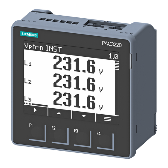
Operator control Device interface 6.1.1 Displays and operator controls The following display and control elements (illustration shows the PAC3220, but the PAC3120 also has the same elements) are on the front panel of the power monitoring devices. ① Display area: Displays the current measured values, device settings and selection menus. -
Page 64: Special Display Elements
Operator control 6.1 Device interface 6.1.2 Special display elements ① Selection bar ② Line separating the start and end of the list ③ Scroll bar of function key F1 (multiple assignments of key F1) ④ Arrow up: Maximum value Arrow down: Minimum value ⑤... -
Page 65: Led
Operator control 6.1 Device interface 6.1.3 The multi-colored LED works like a normal digital output. The user can configure the function, the color and the brightness of the LED. Function Functions Device ON The brightness of the LED changes gradually. Remote control The LED signals remote access to the device. - Page 66 Operator control 6.1 Device interface Functions Remote-controlled color The LED can be switched on by a Modbus com- mand. The LED remains illuminated until the OFF com- mand is registered, or until the set time expires. TIMEOUT: 0 … 18000 s (Timeout 0 s: the LED remains illuminated until the OFF command is received.) DI status...
-
Page 67: Menu Navigation
Operator control 6.1 Device interface 6.1.4 Menu navigation The menu-based navigation is intuitive and largely self-explanatory. Only the basic structure of the menu-based navigation will be explained below. The description and function of the individual parameters can be found in chapter Parameter assignment (Page 69). Menu levels The device menu can be subdivided into four menu levels: ●... -
Page 68: Main Menu Level
Operator control 6.1 Device interface 6.1.4.2 Main menu level In this menu level, all available measured variables are listed without measured values. The main menu level also has a "SETTINGS" selection menu item which can be used to configure the device. ●... -
Page 69: Control Keys
Operator control 6.1 Device interface 6.1.5 Control keys The device can be operated by means of four keys. The keys are assigned different functions. The functions of the keys depend on the menu level currently in use. Keys Possible assignment Meaning Measured value level: The user uses this key to navigate to the next submenu. - Page 70 Operator control 6.1 Device interface PAC3120 and PAC3220 Equipment Manual, 10/2019, L1V30425208F-01...
-
Page 71: Parameter Assignment
Parameter assignment Introduction Device settings The chapter headed "Parameterizing" describes the device settings. These include: ● Adjustment to the physical conditions of use ● Integration into the communication system ● Country-specific settings, ergonomics, device protection It is possible to set the device by means of: ●... -
Page 72: Parameterizing Via The Operator Interface
Parameter assignment 7.2 Parameterizing via the operator interface Parameterizing via the operator interface The power monitoring device can be parameterized via the "Settings" menu option. You can find more information in chapter Menu navigation (Page 65). The device settings are arranged into the following groups. The "SETTINGS" menu shows the choice of groups: ●... -
Page 73: Device Information
Parameter assignment 7.2 Parameterizing via the operator interface 7.2.1 Device information The device information cannot be modified. Device information 7KM3x20-xBA01-1xA0 Article number of the device PAC3x20 Device designation S/N: LQN/230823xxxxxx Serial number of the device D/T: xxxxxx Date code ES: xxx Hardware revision level SW-REV: xxxx Firmware revision level... -
Page 74: Basic Parameters
Parameter assignment 7.2 Parameterizing via the operator interface 7.2.3 Basic parameters Measuring inputs can be parameterized in the "Basic parameters" menu item. Voltage input Selection Range Factory setting Connection type 3P4W 3P4W: • 3 phases, 4 conductors 3P3W: • 3 phases, 3 conductors 3P4WB: •... -
Page 75: Date/Time
Parameter assignment 7.2 Parameterizing via the operator interface Current input Selection Range Factory setting CT PRIMARY Primary current of the current transformers 50 A 1 … 99999 A CT SECONDARY Secondary current of the current transformers • • DISPLAY RANGE: Freely adjustable 50 A 1 …... - Page 76 Parameter assignment 7.2 Parameterizing via the operator interface Selection Range Factory setting DAYL.SAVING Automatic time change. AUTO EU OFF: • Time change is switched off. AUTO EU: • Time change within the European Union The internal clock is put forward from 1 a.m. UTC to 2 a.m.
-
Page 77: Integrated I/Os
Parameter assignment 7.2 Parameterizing via the operator interface 7.2.5 Integrated I/Os Device settings for using the digital inputs and outputs. Digital output Selection Range Factory setting DIG. OUTPUT Two digital outputs are available: – • • ACTION OFF: • Output is deactivated. DEVICE ON: •... - Page 78 Parameter assignment 7.2 Parameterizing via the operator interface Selection Range Factory setting Value of the cumulated power for which a config- urable number of pulses is output. The number of (with PULSE only) pulses to be output is defined in the field "PER". •...
- Page 79 Parameter assignment 7.2 Parameterizing via the operator interface Digital input Selection Range Factory setting DIG. INPUT Two digital inputs are available: – • • ACTION NONE: • The input is switched off. PULSE INPUT: • Counting of input pulses. (Note: A universal counter can be parameter- ized for pulse counting.
- Page 80 Parameter assignment 7.2 Parameterizing via the operator interface Selection Range Factory setting ACTION PULSE OFF: • The LED is switched off. DEVICE ON: • The LED signals that the device is switched The brightness of the LED changes gradually. REMOTE CONTROL: •...
- Page 81 Parameter assignment 7.2 Parameterizing via the operator interface Selection Range Factory setting Colors ORANGE ORANGE • GREEN • CYAN • BLUE • VIOLET • WHITE • • YELLOW • Lighting behavior LED is continuously OFF. LED is continuously ON. LED flashes quickly with varying brightness level.
-
Page 82: Communication
Parameter assignment 7.2 Parameterizing via the operator interface 7.2.6 Communication RS485 interface (applies only to PAC3120 or PAC3220 with RS485 expansion module) Table 7- 1 RS485 interface (applies only to PAC3120) Selection Range Factory setting ADDRESS Range: 1 … 247 BAUD RATE Range: 19200... - Page 83 Parameter assignment 7.2 Parameterizing via the operator interface Ethernet interface (applies only to PAC3220) Table 7- 2 Ethernet interface (applies only to PAC3220) Selection Range Factory setting MAC address. Read only. – Manual setting of the IP address is only possible –...
-
Page 84: Display
Parameter assignment 7.2 Parameterizing via the operator interface 7.2.7 Display Selection Range Factory setting CONTRAST Contrast of the LC display. 0 … 10 BACKLIGHT Intensity of the backlighting of the LC display. 0 … 3 BACKL.DIMMED Intensity of the backlighting of the LC display. Set by the device after the "time until dimmed"... -
Page 85: Advanced
Parameter assignment 7.2 Parameterizing via the operator interface 7.2.8 Advanced 7.2.8.1 Password Password protection prevents the following actions: ● Changing of device settings, including password ● Changing and deletion of values ● Deletion of data and memory content ● Setting and resetting of counts ●... -
Page 86: Write Protection
Parameter assignment 7.2 Parameterizing via the operator interface 7.2.8.2 Write protection The hardware write protection prevents write access to the device, both via the communication interface and on the display. In order to gain write access, the hardware write protection must be deactivated directly on the device. - Page 87 Parameter assignment 7.2 Parameterizing via the operator interface Selection Range Factory setting WRITE PROTECTION Write access is not possible when the hardware – write protection is activated. This parameter is solely a display parameter. The position of the mechanical slider on the rear panel of the device must be adjusted in order to activate or deactivate the protection function.
-
Page 88: Resetting
Parameter assignment 7.2 Parameterizing via the operator interface 7.2.8.3 Resetting Selection Range Factory setting CLEAR MIN/MAX VALUES Resets all minimum and maximum values to the instantaneous value. Yes: active • No: not active • RESET COUNTERS Resets the following counters to zero (0): Energy counters •... -
Page 89: Security Features
Security features The devices are equipped with a range of mechanisms to protect against deliberate and inadvertent device manipulation. ● Password protection ● Hardware write protection ● Device access control (IP filter) (PAC3220 only) ● Configurable Modbus TCP port (PAC3220 only) The closed padlock symbol in the display title indicates whether "password protection"... - Page 90 Security features 8.1 Password protection As soon as the password has been entered in the device once, it is not requested again as long as the "Settings" menu level remains active. Password policy: four-digit number from 0000 to 9999 (default password: 0000) If no user-specific password has been assigned, the default password must be entered when password protection is switched on.
-
Page 91: Hardware Write Protection
Security features 8.2 Hardware write protection Hardware write protection The hardware write protection prevents write access to the device, both via the communication interface and on the display. In order to gain write access, the hardware write protection must be deactivated directly on the device. -
Page 92: Device Access Control (Ip Filter) (Pac3220 Only)
Security features 8.3 Device access control (IP filter) (PAC3220 only) Device access control (IP filter) (PAC3220 only) This function is only available on the PAC3220. The IP filter is a configurable access protection. When the IP filter is activated, Modbus TCP write commands are only accepted if the remote station is located in the same subnet. -
Page 93: Configuring The Modbus Tcp Port (Pac3220 Only)
Security features 8.4 Configuring the Modbus TCP port (PAC3220 only) Configuring the Modbus TCP port (PAC3220 only) This function is only available on the PAC3220. Ports are communication channels which make it possible to access a Modbus-capable device via a network. Standard IP ports like port 502 are often tested by port scanners. If an open port is discovered by an attacker, it can be used to attack the device. - Page 94 Security features 8.4 Configuring the Modbus TCP port (PAC3220 only) PAC3120 and PAC3220 Equipment Manual, 10/2019, L1V30425208F-01...
-
Page 95: Service And Maintenance
Service and maintenance Cleaning Clean the display and the keypad periodically. Use a dry cloth for this. NOTICE Damage due to detergents Detergents can damage the device. Do not use detergents. Firmware update The power monitoring devices support firmware updates. Use the powerconfig configuration software to update the firmware. -
Page 96: Warranty
Procedure Note Loss of warranty Opening the device invalidates the Siemens warranty. Only the manufacturer is permitted to carry out repairs to the device. If the device is defective or damaged, proceed as follows (only during the warranty period): 1. Deinstall the device. You can find more information in chapter Deinstallation (Page 38). -
Page 97: Technical Data
Technical data 10.1 Technical data Device configuration ● 2 opto-isolated digital inputs ● 2 opto-isolated digital outputs ● 1 RS485 interface for connecting to a PC or network (PAC3120 only) ● 2 Ethernet interfaces for connecting to a PC or network (PAC3220 only) Measurement Only for connection to AC voltage systems. - Page 98 Technical data 10.1 Technical data Measuring inputs for voltage Measuring inputs for voltage Measurable voltage Rated voltage 57.7/100 … 400/690 V (IEC) 57.7/100 … 347/600 V (UL) Min. measuring voltage U 11.5 V Max. measuring voltage U 480 V (IEC) 416 V (UL) Zero point suppression level Voltage L-N...
- Page 99 Technical data 10.1 Technical data Measuring accuracy Applied standards: ● IEC 61557-12 ● IEC 62053-21 ● IEC 62053-22 ● IEC 62053-23 Measuring accuracy Measured variable Accuracy class acc. to IEC 61557-12 Voltage Current Apparent power Active power Reactive power Total apparent power over all phases Total active power over all phases Total reactive power VAR1 over all phases Cumulated active power...
- Page 100 Technical data 10.1 Technical data Digital inputs Digital inputs Number Input voltage Rated value 24 V DC Maximum input voltage 30 V DC Switching thresh. signal "1" > 11 V DC Input current For "1" signal Typ. 7 mA Digital outputs Digital outputs Number Type...
- Page 101 Technical data 10.1 Technical data Communication PAC3120 Communication PAC3120 RS485 interface Electrical interface RS485, two-wire line + 1 line for Com- Connection type Screw terminals Supported communication protocol Modbus RTU Functionality Slave Supported baud rate 4800 • 9600 • 19200 •...
- Page 102 Technical data 10.1 Technical data Display and operator control Display and operator control Display Version Monochrome, graphical LC display Backlighting White, invertible display Service life of the LEDs 25,000 hours at 25 °C ambient temper- ature. To achieve a service life of at least 10 years, the backlighting should be switched on for no more than 10 % of the device operating time.
- Page 103 Technical data 10.1 Technical data Connection components: Current connection, voltage connection Connection components: Current connection, voltage connection Conductor cross-section for copper Rigid 0.2 … 6 mm cable (Cu) (AWG 24 … 10) Flexible 0.2 … 4 mm (AWG 24 … 12) Flexible with end sleeve, without plastic 0.2 …...
- Page 104 Technical data 10.1 Technical data Connection components: Communication ports PAC3120 Connection components: Communication ports PAC3120 Conductor cross-section for copper Rigid 0.14 … 1.5 mm cable (Cu) (AWG 26 … 16) Flexible 0.14 … 1.5 mm (AWG 26 … 16) Flexible with end sleeve, without plastic 0.25 …...
- Page 105 Technical data 10.1 Technical data Dimensions and weights Dimensions and weights Type of mounting Panel mounting to IEC 61554 Enclosure dimensions W x H x D 96 mm x 96 mm x 56 mm Cutout (W x H) 92 mm +0.8 mm x 92 mm +0.8 mm Mounting depth (without expansion modules) 51 mm Permissible switching panel thickness for installation...
- Page 106 Technical data 10.1 Technical data Ambient conditions The device is suitable for switch panel mounting in accordance with IEC 61554. The device may only be operated within enclosed dry rooms. Ambient conditions Temperature range Ambient temperature −25 … +55 °C (K55) during operation Ambient temperature −25 …...
- Page 107 (valid in Russia, Belarus, Kazakhstan, Kyrgyzstan and Armenia) (available soon) Products with this symbol meet both UL and Canadian requirements. (available soon) KCC test symbol (Korea) You can download the relevant certificates from the Siemens Support website (https://support.industry.siemens.com): ● PAC3120 (https://support.industry.siemens.com/cs/ww/de/ps/7KM3120-1BA01- 1EA0/cert) ●...
-
Page 108: Labeling
Technical data 10.2 Labeling 10.2 Labeling Figure 10-1 View of a typical rating plate illustrated by the example of a PAC3220 (230 V) device PAC3120 and PAC3220 Equipment Manual, 10/2019, L1V30425208F-01... - Page 109 Technical data 10.2 Labeling Table 10- 1 Legend Item Symbol, Explanation label ① – Article number ② – MAC address ③ – Device supply voltage ④ – Data about measuring inputs for voltage ⑤ CE marking (European Union) ⑥ RCM test symbol (Australia and New Zealand) ⑦...
- Page 110 Technical data 10.2 Labeling PAC3120 and PAC3220 Equipment Manual, 10/2019, L1V30425208F-01...
-
Page 111: Dimensional Drawings
Dimensional drawings Panel cutout Figure 11-1 Panel cutout Frame dimensions Figure 11-2 Frame dimensions PAC3120 and PAC3220 Equipment Manual, 10/2019, L1V30425208F-01... - Page 112 Dimensional drawings Clearance measurements if mounting brackets supplied with the device are used 30 mm L = 5 mm if compact brackets available to order as separate components are used (article number: 7KM9900-0GA00-0AA0) PAC3120 and PAC3220 Equipment Manual, 10/2019, L1V30425208F-01...
-
Page 113: Appendix
Appendix Modbus Detailed information about Modbus can be found at the Modbus website (http://www.modbus.org). A.1.1 Function codes Function codes control the data exchange. To do this, a function code tells the slave which action it is to take. If an error occurs, the MSB bit is set in the response frame in the FC byte. Supported Modbus function codes Table A- 1 Supported Modbus function codes... -
Page 114: Exception Codes
Appendix A.1 Modbus A.1.2 Exception codes Overview Table A- 2 Modbus exception codes Exception codes Name Meaning Remedy Illegal Function Illegal function: Check which function codes are supported. The function code in the request is not a • permissible action for the slave. The slave is in a status in which it cannot •... -
Page 115: Modbus Measured Variables With The Function Codes 0X03 And 0X04
Appendix A.1 Modbus A.1.3 Modbus measured variables with the function codes 0x03 and 0x04 Addressing the measured variables You can use the Modbus function codes 0x03 and 0x04 on all the measured variables listed below. Note Error in the case of inconsistent access to measured values Please ensure the start offset of the register is correct for read access operations. - Page 116 Appendix A.1 Modbus Offset Number of Name Format Unit Value range Access registers Active power L3 Float – Reactive power L1 (VAR1) Float – Reactive power L1 (VAR1) Float – Reactive power L1 (VAR1) Float – Power factor L1 Float –...
- Page 117 Appendix A.1 Modbus Offset Number of Name Format Unit Value range Access registers Maximum reactive power L1 Float – (VARn) Maximum power factor L1 Float – 0 … 1 Maximum power factor L2 Float – 0 … 1 Maximum power factor L3 Float –...
- Page 118 Appendix A.1 Modbus Offset Number of Name Format Unit Value range Access registers Minimum power factor L2 Float – 0 … 1 Minimum power factor L3 Float – 0 … 1 Minimum frequency Float 45 … 65 Minimum average voltage UL Float –...
- Page 119 Appendix A.1 Modbus Offset Number of Name Format Unit Value range Access registers Status digital inputs module 1 Unsigned long – Byte3 Bit0 Input 4.0 Byte3 Bit1 Input 4.1 Byte3 Bit2 Input 4.2 Byte3 Bit3 Input 4.3 Status digital outputs module 2 Unsigned long –...
- Page 120 Appendix A.1 Modbus Offset Number of Name Format Unit Value range Access registers L1 active energy import tariff 1 Double Overflow 1.0e+12 L1 active energy import tariff 2 Double Overflow 1.0e+12 L1 active energy export tariff 1 Double varh Overflow 1.0e+12 L1 active energy export tariff 2 Double varh...
-
Page 121: Structure - Digital Input Status And Digital Output Status With The Function Codes 0X03 And 0X04
Appendix A.1 Modbus A.1.4 Structure - Digital input status and digital output status with the function codes 0x03 and 0x04 The following are available via Modbus: ● "Digital Inputs Status" ● "Digital Outputs Status" Table A- 5 Structure - status of the digital inputs (Modbus offset 209) and digital outputs (Modbus offset 207) Name Length Status... -
Page 122: Structure - Device Diagnostics And Device Status With The Function Codes 0X03 And 0X04
Appendix A.1 Modbus A.1.5 Structure - Device diagnostics and device status with the function codes 0x03 and 0x04 Design Table A- 8 Modbus offset 205, register 2: Structure device status and device diagnostics Byte Device status Type Bit mask Value range Access No synchronization pulse Status... -
Page 123: Modbus Status Parameters With The Function Code 0X02
Appendix A.1 Modbus A.1.6 Modbus status parameters with the function code 0x02 Status parameters You can use the Modbus function code 0x02 on all the status parameters listed below. Table A- 9 Status parameters Offset Number of Name Format Value range Access registers Limit 0... - Page 124 Appendix A.1 Modbus Offset Number of Name Format Value range Access registers Digital input 8.3 Digital output 0.0 Digital output 0.1 Digital output 4.0 Digital output 4.1 Digital output 8.0 Digital output 8.1 Applies only to PAC3220 and 4DI/2DO expansion module PAC3120 and PAC3220 Equipment Manual, 10/2019, L1V30425208F-01...
-
Page 125: Modbus Settings With The Function Codes 0X03, 0X04 And 0X10
Appendix A.1 Modbus A.1.7 Modbus settings with the function codes 0x03, 0x04 and 0x10 Addressing the settings You can use the Modbus function codes 0x03 and 0x04 for read access operations and 0x10 for write access operations on all the setting parameters listed below. Table A- 10 Setting parameters Offset... - Page 126 Appendix A.1 Modbus Offset Number of Name Unit Format Value range Access registers 50035 DO 0.0 Type of use – Unsigned 0 … 5 long 0 = No action 1 = Device active 2 = Switching output 3 = Direct. of rotation 4 = Limit value 5 = Pulse output 50037...
- Page 127 Appendix A.1 Modbus Offset Number of Name Unit Format Value range Access registers 50061 Display time until dimmed Unsigned 0 … 99 long 50063 Limit 0 ON/OFF – Unsigned 0 … 1 long 0 = Off 1 = On 50065 Limit 0 Hysteresis Float 0.0 …...
- Page 128 Appendix A.1 Modbus Offset Number of Name Unit Format Value range Access registers 50103 Limit 2 Type ≥/< – Unsigned 0 … 1 long 0 = Greater than 1 = Smaller than 50105 Limit 3 ON/OFF – Unsigned 0 … 1 long 0 = Off 1 = On...
- Page 129 Appendix A.1 Modbus Offset Number of Name Unit Format Value range Access registers 50145 Limit 5 Type ≥/< – Unsigned 0 … 1 long 0 = Greater than 1 = Smaller than 50147 DO 0.0 Timeout – Unsigned 0.1 … 18000 long Digital output remote timeout 1 …...
- Page 130 Appendix A.1 Modbus Offset Number of Name Unit Format Value range Access registers 50235 Time zone Min. Long MODULO(30)==0 50237 DO 0.0 Pulse divider – Unsigned 0 … 3 long 0 = 1 kWh 1 = 10 kWh 2 = 100 kWh 3 = 1000 kWh 50239 DI 0.0 Pulse divider...
- Page 131 Appendix A.1 Modbus Offset Number of Name Unit Format Value range Access registers 51211 DI 4.0 Index – Unsigned 0 … 1 short 0 = kWh 1 = kvarh 51212 DI 4.0 Pulses per kWh/kvarh – Unsigned 1 … 4000 short 51213 DI 4.0 Pulse divider...
- Page 132 Appendix A.1 Modbus Offset Number of Name Unit Format Value range Access registers 51231 DI 8.0 Index – Unsigned 0 … 1 short 0 = kWh 1 = kvarh 51232 DI 8.0 Pulses per kWh/kvarh – Unsigned 1 … 4000 short 51233 DI 8.0 Pulse divider...
- Page 133 Appendix A.1 Modbus Offset Number of Name Unit Format Value range Access registers 51712 DO 0.0 Type of use – Unsigned 0 … 5 short 0 = No action 1 = Device active 2 = Switching output 3 = Direct. of rotation 4 = Limit value 5 = Pulse output 51713...
- Page 134 Appendix A.1 Modbus Offset Number of Name Unit Format Value range Access registers 51724 DO 0.1 Index – Unsigned 0 … 3 short 0 = Import kWh 1 = Export kWh 2 = Import kvarh 3 = Export kvarh 51725 DO 0.1 Pulses per kWh/kvarh –...
- Page 135 Appendix A.1 Modbus Offset Number of Name Unit Format Value range Access registers 51737 DO 4.0 Pulse divider – Unsigned 0 … 3 short 0 = 1 kWh 1 = 10 kWh 2 = 100 kWh 3 = 1000 kWh 51738 DO 4.1 Group assignment –...
- Page 136 Appendix A.1 Modbus Offset Number of Name Unit Format Value range Access registers 51749 DO 8.0 Limit value index – Unsigned 0 … 6 short 0 = Comb. limit 1 = Limit0 2 = Limit1 3 = Limit2 4 = Limit3 5 = Limit4 6 = Limit5 51751...
- Page 137 Appendix A.1 Modbus Offset Number of Name Unit Format Value range Access registers 51762 DO 8.1 Pulse length – Unsigned 30 … 500 short 51763 DO 8.1 Timeout – Unsigned 0.1 … 18000 short Digital output remote timeout 1 … 18000 s, 0 = Disables timeout (default) 51764 DO 8.1 Pulse divider...
-
Page 138: Modbus Communication Parameters With The Function Codes 0X03, 0X04 And 0X10
Appendix A.1 Modbus A.1.8 Modbus communication parameters with the function codes 0x03, 0x04 and 0x10 Addressing the communication parameters Table A- 11 Addressing the communication parameters Offset Number of Name Format Value range Access registers 62983 Aggregation file 1 Unsigned >... - Page 139 Appendix A.1 Modbus Offset Number of Name Format Value range Access registers 63023 Data bits Unsigned 0 = 8N2 long Parity bits 1 = 8E1 Stop bits 2 = 8O1 3 = 8N1 63025 Response time Unsigned 0 … 255 long Applies only to the PAC RS485 expansion module Applies only to the PAC3220...
-
Page 140: Modbus Command Parameters
Appendix A.1 Modbus A.1.9 Modbus command parameters Addressing the command parameters You can use Modbus function code 0x06 on the command parameters. Table A- 13 Command parameters Offset Number of Name Unit Format Value range Access registers 60000 Reset the device to the factory set- –... -
Page 141: Modbus Standard Device Identification With The Function Code 0X2B
Appendix A.1 Modbus Offset Number of Name Unit Format Value range Access registers Byte0 1 = Output 0.1 Byte0 64 = Output 4. Byte0 65 = Output 4.1 Byte0 128 Output 8.0 Byte0 129 Output 8.1 Byte1 0 = Byte1 1 = 60009 Switching command for vector group –... -
Page 142: Demand Value Measured Variables With Modbus Function Code 0X14
Appendix A.1 Modbus A.1.11 Demand value measured variables with Modbus function code 0x14 The measured variables listed below can be read out via Modbus function code 0x14 "Read File Record" in two stages. ● Stage 1 (File Number 1), preset to 10 s ●... - Page 143 Appendix A.1 Modbus File Offset Address Length Name Format Access (FC0x14) Address FC 0x03 FC 0x04 30067 VA_SUM Float 30069 P_SUM Float 30071 VARQ1_SUM Float 30073 PF_SUM Float 30075 V_BAL Float 30077 I_BAL Float 30079 Float 30257 Time stamp aggregation stage n UNIX_TS 30259 Flags aggregation stage n...
- Page 144 Appendix A.1 Modbus File Offset Address Length Name Format Access (FC0x14) Address FC 0x03 FC 0x04 30323 max_VA_SUM Float 30325 max_P_SUM Float 30327 max_VARQ1_SUM Float 30329 max_PF_SUM Float 30331 max_V_BAL Float 30333 max_I_BAL Float 30335 max_I_N Float 30513 Time stamp aggregation stage n UNIX_TS 30515 Flags aggregation stage n...
- Page 145 Appendix A.1 Modbus File Offset Address Length Name Format Access (FC0x14) Address FC 0x03 FC 0x04 30579 min_VA_SUM Float 30581 min_P_SUM Float 30583 min_VARQ1_SUM Float 30585 min_PF_SUM Float 30587 min_V_BAL Float 30589 min_I_BAL Float 30591 min_I_N Float 31001 Time stamp aggregation stage n UNIX_TS 31003 Flags aggregation stage n...
- Page 146 Appendix A.1 Modbus File Offset Address Length Name Format Access (FC0x14) Address FC 0x03 FC 0x04 31067 VA_SUM Float 31069 P_SUM Float 31071 VARQ1_SUM Float 31073 PF_SUM Float 31075 V_BAL Float 31077 I_BAL Float 31079 Float 31257 Time stamp aggregation stage n UNIX_TS 31259 Flags aggregation stage n...
- Page 147 Appendix A.1 Modbus File Offset Address Length Name Format Access (FC0x14) Address FC 0x03 FC 0x04 31323 max_VA_SUM Float 31325 max_P_SUM Float 31327 max_VARQ1_SUM Float 31329 max_PF_SUM Float 31331 max_V_BAL Float 31333 max_I_BAL Float 31335 max_I_N Float 31513 Time stamp aggregation stage n UNIX_TS 31515 Flags aggregation stage n...
- Page 148 Appendix A.1 Modbus File Offset Address Length Name Format Access (FC0x14) Address FC 0x03 FC 0x04 31579 min_VA_SUM Float 31581 min_P_SUM Float 31583 min_VARQ1_SUM Float 31585 min_PF_SUM Float 31587 min_V_BAL Float 31589 min_I_BAL Float 31591 min_I_N Float PAC3120 and PAC3220 Equipment Manual, 10/2019, L1V30425208F-01...
-
Page 149: Active Energy History With Modbus Function Code 0X14
Appendix A.1 Modbus A.1.12 Active energy history with Modbus function code 0x14 The active energy counters listed below can be read out via Modbus function code 0x14 "Read File Record". ● The daily energy counter (file number 90) records the active energy for each day of the preceding two months. - Page 150 Appendix A.1 Modbus File Offset Address Length Name Format Access (FC0x14) address FC0x03 FC0x04 32065 Work portion Tariff 1 Float 32067 Work portion Tariff 2 Float 32069 TS of day – 11 UNIX_TS (UTC) 32071 Work portion Tariff 1 Float 32073 Work portion Tariff 2 Float...
- Page 151 Appendix A.1 Modbus File Offset Address Length Name Format Access (FC0x14) address FC0x03 FC0x04 32145 Work portion Tariff 2 Float 32147 TS of day – 24 UNIX_TS (UTC) 32149 Work portion Tariff 1 Float 32151 Work portion Tariff 2 Float 32153 TS of day –...
- Page 152 Appendix A.1 Modbus File Offset Address Length Name Format Access (FC0x14) address FC0x03 FC0x04 32225 TS of day – 37 UNIX_TS (UTC) 32227 Work portion Tariff 1 Float 32229 Work portion Tariff 2 Float 32231 TS of day – 38 UNIX_TS (UTC) 32233 Work portion Tariff 1...
- Page 153 Appendix A.1 Modbus File Offset Address Length Name Format Access (FC0x14) address FC0x03 FC0x04 32305 Work portion Tariff 1 Float 32307 Work portion Tariff 2 Float 32309 TS of day – 51 UNIX_TS (UTC) 32311 Work portion Tariff 1 Float 32313 Work portion Tariff 2 Float...
- Page 154 Appendix A.1 Modbus File Offset Address Length Name Format Access (FC0x14) address FC0x03 FC0x04 32385 Work portion Tariff 2 Float 32387 TS of day – 64 UNIX_TS (UTC) 32389 Work portion Tariff 1 Float 32391 Work portion Tariff 2 Float File Offset Address...
- Page 155 Appendix A.1 Modbus File Offset Address Length Name Format Access (FC0x14) Address FC 0x03 FC 0x04 32463 TS of month – 10 UNIX_TS (UTC) 32465 Work portion Tariff 1 Float 32467 Work portion Tariff 2 Float 32469 TS of month – 11 UNIX_TS (UTC) 32471 Work portion Tariff 1...
- Page 156 Appendix A.1 Modbus File Offset Address Length Name Format Access (FC0x14) Address FC 0x03 FC 0x04 32543 Work portion Tariff 1 Float 32545 Work portion Tariff 2 Float 32547 TS of month – 24 UNIX_TS (UTC) 32549 Work portion Tariff 1 Float 32551 Work portion Tariff 2...
-
Page 157: Index
Index Error code, 113 Ethernet interface, 99 Exception code, 112 Ambient conditions, 104 Frame dimensions, 109 Function code, 111, 139 Bit mask, 120 General safety notes, 10 Cleaning, 93 Clearance measurements, 110 Command parameters, 138 Communication, 29, 53, 99, 99 Communication parameters, 136 Installation space Connection... - Page 158 Index Screw terminal, 101 Supply voltage, 97 Panel cutout Technical Support, 8 Dimensions, 109 Turn-off time, 28 Parameter Status, 121 Parameter assignment Device settings, 69 Parameters Ventilation Command, 138 Installation space, 36 Communication, 136 Device information, 139 Power demand, 14, 22 Prerequisites Startup, 55 Procedure...