Table of Contents
Advertisement
Quick Links
SENTRON
Power Monitoring Device
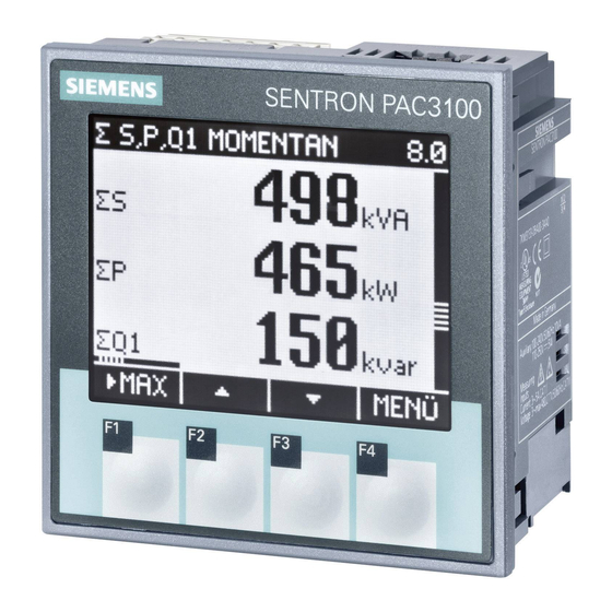
SENTRON PAC3100
Manual
07/2009
A5E02385159B-01
Introduction
Safety notes
Description
Operation planning
Mounting
Connection
Commissioning
Operator control
Parameterizing
Service and maintenance
Technical data
Dimensional drawings
Appendix
ESD guidelines
List of abbreviations
1
2
3
4
5
6
7
8
9
10
11
12
A
B
C
Advertisement
Table of Contents

Related Manuals for Siemens SENTRON PAC3100


Summary of Contents for Siemens SENTRON PAC3100
- Page 1 Introduction Safety notes Description SENTRON Operation planning Power Monitoring Device SENTRON PAC3100 Mounting Connection Manual Commissioning Operator control Parameterizing Service and maintenance Technical data Dimensional drawings Appendix ESD guidelines List of abbreviations 07/2009 A5E02385159B-01...
- Page 2 Note the following: WARNING Siemens products may only be used for the applications described in the catalog and in the relevant technical documentation. If products and components from other manufacturers are used, these must be recommended or approved by Siemens. Proper transport, storage, installation, assembly, commissioning, operation and maintenance are required to ensure that the products operate safely and without any problems.
-
Page 3: Table Of Contents
Tools ............................32 5.2.2 Mounting dimensions ........................32 5.2.3 Installation steps ..........................32 Deinstallation..........................36 Connection .............................. 39 Safety notes ..........................39 Connections ..........................40 Connecting the cables to the terminals..................45 Connection examples ........................45 Connecting to the RS 485 bus .....................48 SENTRON PAC3100 Manual, 07/2009, A5E02385159B-01... - Page 4 Password management ......................95 9.2.11.1 Calling password management....................95 9.2.11.2 Switch on password protection ....................96 9.2.11.3 Switch off password protection ....................97 9.2.11.4 Change password ........................97 9.2.11.5 Password lost - what to do? ......................98 SENTRON PAC3100 Manual, 07/2009, A5E02385159B-01...
- Page 5 Modbus command parameters ....................139 A.2.13 MODBUS standard device identification with the function code 0x2B ........140 Correction sheet.........................141 ESD guidelines ............................143 Electrostatic sensitive devices (ESD) ..................143 List of abbreviations..........................145 Abbreviations ..........................145 Glossary ..............................147 Index..............................149 SENTRON PAC3100 Manual, 07/2009, A5E02385159B-01...
- Page 6 Table A- 19 Command parameters ......................139 Table A- 20 MODBUS standard device identification parameters ............... 140 Table A- 21 Errors, comments, and suggestions for improvements ............141 Table C- 1 Meaning of abbreviations ......................145 SENTRON PAC3100 Manual, 07/2009, A5E02385159B-01...
-
Page 7: Sentron Pac3100 Manual, 07/2009, A5E02385159B-01
Bus termination using external resistor..................50 Figure 7-1 Language selection........................53 Figure 7-2 "SETTINGS" menu........................54 Figure 7-3 "LANGUAGE" edit mode......................54 Figure 7-4 "CONNECTION TYPE" device setting..................55 Figure 7-5 "USE PTs?" device setting......................56 Figure 7-6 "USE PTs?" device setting switched on ..................57 SENTRON PAC3100 Manual, 07/2009, A5E02385159B-01... - Page 8 Figure 9-6 "POWER DEMAND" device setting .................... 88 Figure 9-7 "INTEGRATED I/O" device setting....................89 Figure 9-8 Device setting "DIG. OUTPUT 0"....................90 Figure 9-9 "DISPLAY" device setting ......................92 Figure 9-10 "ADVANCED" device setting....................... 93 SENTRON PAC3100 Manual, 07/2009, A5E02385159B-01...
- Page 9 "PASSWORD PROTECTION" device setting................96 Figure 11-1 Device labeling...........................113 Figure 12-1 Panel cutout ..........................115 Figure 12-2 Frame dimensions ........................116 Figure 12-3 Side-by-side installation ......................116 Figure 12-4 Clearances ..........................117 Figure A-1 11-bit character frame........................126 Figure A-2 10-bit character frame........................126 SENTRON PAC3100 Manual, 07/2009, A5E02385159B-01...
- Page 10 Table of contents SENTRON PAC3100 Manual, 07/2009, A5E02385159B-01...
-
Page 11: Introduction
Introduction Purpose of this document This present manual describes the SENTRON PAC3100 Power Monitoring Device. It is intended for the use of: ● Planners ● Plant operators ● Commissioning engineers ● Service and maintenance personnel Required basic knowledge A general knowledge of the field of electrical engineering is required to understand this manual. -
Page 12: Components Of The Product
This will help us to improve the next edition of the manual. Further documentation Overview You can find more information in the "SENTRON PAC3100" Operating Instructions and on the Internet. See also Latest information and correction sheet (Page 12) -
Page 13: Safety Notes
Hazardous Voltage Will cause death or serious injury. Turn off and lock out all power supplying this device before working on this device. Safety-related symbols on the device N117 Figure 2-1 Safety-related symbols on the device SENTRON PAC3100 Manual, 07/2009, A5E02385159B-01... - Page 14 Safety notes Symbol Meaning Risk of electric shock General Warning Symbol See also Applying the supply voltage (Page 51) Applying the measuring voltage (Page 60) Applying the measuring current (Page 61) SENTRON PAC3100 Manual, 07/2009, A5E02385159B-01...
-
Page 15: Description
The integrated RS 485 interface can be used for communication. In addition, the SENTRON PAC3100 has 2 digital inputs and 2 digital outputs. The parameters can be set either direct on the device or via the RS 485 interface. - Page 16 ● 2 digital inputs with internal power supply for status monitoring. ● 2 digital outputs, programmable as energy pulse outputs for active energy pulses or reactive energy pulses, or as switching outputs for remote control via the RS 485 interface. SENTRON PAC3100 Manual, 07/2009, A5E02385159B-01...
-
Page 17: Measuring Inputs
AC current measurement only The device is not suitable for measuring DC current. SENTRON PAC3100 is designed for: ● Measuring current of 5 A for connecting standard current transformers. Each current measuring input can take a continuous load of 10 A (max. 300 V). Surge withstand capability is possible for currents up to 100 A and a duration of 1 s. -
Page 18: Table 3- 2 Available Connection Types
CAUTION The wrong system connection can destroy the device Before connecting SENTRON PAC3100, you must ensure that the local power supply conditions agree with the specifications on the type plate. The short code of the connection type must be entered in the device settings at startup. You can find the instructions for parameterizing the connection type in the chapter "Commissioning". -
Page 19: Table 3- 3 Display Of The Measured Variables Depending On The Connection Type
Total reactive power VAR1 over all phases ✓ ✓ Total power factor ✓ ✓ Line frequency ✓ ✓ Active energy ✓ ✓ Reactive energy ✓ ✓ Cumulated active power ✓ ✓ Cumulated reactive power ✓ ✓ SENTRON PAC3100 Manual, 07/2009, A5E02385159B-01... -
Page 20: Figure 3-3 Indicating Overload On The Display
See also Connection examples (Page 45) Setting the connection type (Page 55) Connection (Page 39) Applying the measuring voltage (Page 60) Applying the measuring current (Page 61) SENTRON PAC3100 Manual, 07/2009, A5E02385159B-01... -
Page 21: Measured Variables
1) Power demand of the last completed period for import and export, as well as minimum and maximum instantaneous value. Can only be called via RS 485 interface. See the chapter "Power demand". See also Measured variables (Page 119) Power demands and counters (Page 22) SENTRON PAC3100 Manual, 07/2009, A5E02385159B-01... -
Page 22: Power Demands And Counters
3.4.1 Acquisition of power demand Values that can be read out SENTRON PAC3100 supplies the power demand of the last completed measuring period: ● Mean values for active power and reactive power, separated in each case for import and export ●... -
Page 23: Energy Counters
Description 3.5 Digital inputs and outputs 3.4.2 Energy counters Energy counters SENTRON PAC3100 has energy counters for counting ● Active energy import ● Active energy export ● Reactive energy import ● Reactive energy export The device also calculates the energy balance ●... -
Page 24: Digital Inputs
Both digital inputs have an internal power supply. They can be operated optionally with or without an external power supply. Switch with internal power supply Internal power supply on terminal DIC. Functional ground terminal Figure 3-6 Digital inputs with switch and internal power supply on terminal DIC SENTRON PAC3100 Manual, 07/2009, A5E02385159B-01... -
Page 25: Digital Outputs
The digital output supplies a number of pulses proportional to one of the following energies: ● Active energy import ● Active energy export ● Reactive energy import ● Reactive energy export Figure 3-8 Energy pulse output SENTRON PAC3100 Manual, 07/2009, A5E02385159B-01... -
Page 26: Rs 485 Interface
See also Modbus RTU (Page 125) RS 485 interface RS 485 interface for Modbus RTU communication The SENTRON PAC3100 is equipped with an RS 485 interface for Modbus RTU communication. Application This interface permits: ● Reading out the measured values ●... -
Page 27: Table 3- 5 Default Modbus Rtu Communication Settings
The delay time is individually adjustable between 1 and 255 milliseconds. Polarization Polarization of the RS 485 data lines must be implemented at another point on the bus. The PAC3100 does not contain polarization resistors. SENTRON PAC3100 Manual, 07/2009, A5E02385159B-01... -
Page 28: Slots On The Rear Of The Device
Green Flashing Other devices are communicating on the bus. Yellow Flashing The SENTRON PAC3100 is sending data. See also Connecting to the RS 485 bus (Page 48) Modbus RTU (Page 125) Slots on the rear of the device Slot on the rear of the device... -
Page 29: Operation Planning
Operation planning Mounting location The SENTRON PAC3100 device is intended for installation in permanently installed switching panels within closed rooms. Conductive panels and doors on control cabinets must be grounded. The doors of the control cabinet must be connected to the control cabinet using a grounding cable. -
Page 30: Table 4- 1 Environmental Conditions
IP20 Circuit breaker A suitable circuit breaker must be connected upstream of SENTRON PAC3100 in order to permit disconnection of the device from the power supply! ● The circuit breaker must be mounted close to the device and be easily accessible to the user. -
Page 31: Mounting
● Make sure that the contents of the package are complete ● Check the device for external damage Please contact your Siemens sales partner in the following cases: ● The packaging is damaged ● The contents of the package are not complete ●... -
Page 32: Mounting On The Switching Panel
Chapter "Dimensional drawings". See also Dimensional drawings (Page 115) 5.2.3 Installation steps Proceed as follows to install the SENTRON PAC3100 in the switching panel: Procedure 1. Cut a hole in the panel measuring 92.0 x 92.0 (if not already available). - Page 33 Fig. "Installation step E" at location (3) using a self-adhesive cable clamp or other suitable small installation accessory. Installation is complete. NOTICE Ensure that no tools or other potentially hazardous objects have been left at the installation location. SENTRON PAC3100 Manual, 07/2009, A5E02385159B-01...
- Page 34 5.2 Mounting on the switching panel Installation steps S IE M E N S S E N T R O N P A C 3 1 0 0 Installation step A Installation step B Installation step B, detail SENTRON PAC3100 Manual, 07/2009, A5E02385159B-01...
- Page 35 Mounting 5.2 Mounting on the switching panel Installation step C Installation step D SENTRON PAC3100 Manual, 07/2009, A5E02385159B-01...
-
Page 36: Deinstallation
5.3 Deinstallation Installation step E – Strain relief of the RS 485 connection See also ESD guidelines (Page 143) Deinstallation Tools You require the following tools to deinstall the device: ● PH2 screwdriver ● Slotted screwdriver SENTRON PAC3100 Manual, 07/2009, A5E02385159B-01... -
Page 37: Figure 5-1 Deinstallation, Releasing The Locking Hooks
6. Pack the device into the original box together with the operating instructions and the delivered components listed in the operating instructions. Deinstallation is complete. Figure 5-1 Deinstallation, releasing the locking hooks See also ESD guidelines (Page 143) SENTRON PAC3100 Manual, 07/2009, A5E02385159B-01... - Page 38 Mounting 5.3 Deinstallation SENTRON PAC3100 Manual, 07/2009, A5E02385159B-01...
-
Page 39: Connection
Before power is applied to the device for the first time, it must have been located in the operating area for at least two hours in order to reach temperature balance and avoid humidity and condensation. Condensation on the device is not permissible during operation. SENTRON PAC3100 Manual, 07/2009, A5E02385159B-01... -
Page 40: Connections
Applying the measuring voltage (Page 60) Applying the measuring current (Page 61) Connections DANGER Hazardous Voltage Will cause death, serious injury or considerable property damage. Observe the safety information on the device and in the operating instructions and the manual. SENTRON PAC3100 Manual, 07/2009, A5E02385159B-01... -
Page 41: Figure 6-1 Connection Designations, View Of The Rear And Top Of The Device
Dummy connections. Cannot be used as slots! Supply voltage L+, N/- Measuring inputs voltage V Measuring inputs current IL1, IL2, IL3 RS 485 connector Figure 6-1 Connection designations, view of the rear and top of the device SENTRON PAC3100 Manual, 07/2009, A5E02385159B-01... -
Page 42: Figure 6-2 Terminal Labeling
AC: Connection: Neutral conductor DC: Connection: - (13) Functional ground (14) Digital input (common) (15) Digital input 1 (16) Digital input 0 (17) Digital output (common) (18) Digital output 1 (19) Digital output 0 Figure 6-2 Terminal labeling SENTRON PAC3100 Manual, 07/2009, A5E02385159B-01... -
Page 43: Figure 6-3 Terminal Labeling
"functional ground" discharges interference affecting the digital inputs and outputs and the RS 485 interface. Connect the functional ground to the equipotential bonding strip in the control cabinet. The maximum cable length for connecting the functional ground is 3 meters. SENTRON PAC3100 Manual, 07/2009, A5E02385159B-01... - Page 44 Non-fused voltage measuring points may lead to device and equipment damage. Always protect the device with an IEC approved or UL listed 10 A fuse, circuit breaker or supplementary protector. Never short circuit the secondary connections of the voltage transformers. SENTRON PAC3100 Manual, 07/2009, A5E02385159B-01...
-
Page 45: Connecting The Cables To The Terminals
It can be grounded at either the "k" or the "l" terminal. The grounding has no impact on the measurement. The wiring method must be made known to the device in the device settings. The connection types given below refer to the device parameterization. SENTRON PAC3100 Manual, 07/2009, A5E02385159B-01... -
Page 46: Figure 6-6 Connection Type 3P4W, Without Voltage Transformer, With Three Current Transformers
(2) Three-phase measuring, four conductors, unbalanced load, with voltage transformers, with three current transformers Connection type 3P4W Fuses must be provided by the customer. Connection of supply voltage Figure 6-7 Connection type 3P4W, with voltage transformer, with three current transformers SENTRON PAC3100 Manual, 07/2009, A5E02385159B-01... -
Page 47: Figure 6-8 Connection Type 3P3W, Without Voltage Transformer, With Three Current Transformers
(4) Three-phase measuring, three conductors, unbalanced load, with voltage transformers, with three current transformers Connection type 3P3W Fuses must be provided by the customer. Connection of supply voltage Figure 6-9 Connection type 3P3W, with voltage transformer, with three current transformers SENTRON PAC3100 Manual, 07/2009, A5E02385159B-01... -
Page 48: Connecting To The Rs 485 Bus
Connecting to the RS 485 bus Procedure Connect the SENTRON PAC3100 to the RS 485 bus via the integral interface. Please pay attention here to the general topology of the two-wire line. 1. Connect the RS 485 cables to the screw terminals of the terminal block. -
Page 49: Figure 6-11 Rs 485 Terminal Block
Bus termination resistor (termination) Pull-up resistor Pull-down resistor Grounding of the cable shielding Grounding of the common line, preferably only at one point for the whole bus Figure 6-12 Block diagram: General RS 485 topology SENTRON PAC3100 Manual, 07/2009, A5E02385159B-01... -
Page 50: Figure 6-13 Bus Termination Using External Resistor
The PAC3100 does not support bus termination. The bus can be terminated using an external resistor ≥ 60 Ω. The resistor must be connected to terminals -/A and -/B of the RS 485 terminal block. Figure 6-13 Bus termination using external resistor SENTRON PAC3100 Manual, 07/2009, A5E02385159B-01... -
Page 51: Commissioning
Check the connections Incorrect connection can result in malfunctions and failure of the device. Before starting up the SENTRON PAC3100, check that all connections are correct. Applying the supply voltage A supply voltage is required to operate the device. Please consult the technical data or the type plate for the type and level of the possible supply voltage. -
Page 52: Table 7- 1 Connection Of Supply Voltage
AC: Connection: Conductor (phase-to-neutral voltage) DC: Connection: + AC: Connection: Neutral conductor DC: Connection: - See also Safety notes (Page 13) Safety notes (Page 39) Applying the measuring voltage (Page 60) Technical data (Page 105) SENTRON PAC3100 Manual, 07/2009, A5E02385159B-01... -
Page 53: Parameterizing The Device
First, set the language in which the display text is to appear. The available languages are displayed: ● at initial startup, ● after resetting to factory settings English is the default language. Figure 7-1 Language selection SENTRON PAC3100 Manual, 07/2009, A5E02385159B-01... -
Page 54: Figure 7-2 "Settings" Menu
8. Accept the desired language with: <F4> The language is permanently saved and becomes effective immediately. The display returns to display mode. 9. Return to one of the selection menus or to the measured values display: <F1> SENTRON PAC3100 Manual, 07/2009, A5E02385159B-01... -
Page 55: Voltage Input
<F2> or <F3> 5. Call the "BASIC PARAMETERS" entry: <F4> 6. In the "BASIC PARAMETERS" menu, call the "VOLTAGE INPUTS" entry: <F4> The display shows the currently valid settings. Figure 7-4 "CONNECTION TYPE" device setting SENTRON PAC3100 Manual, 07/2009, A5E02385159B-01... -
Page 56: Measurement Using Voltage Transformers
Off: Measurement direct on the low-voltage system. The device setting is saved permanently and becomes effective immediately. The display remains in display mode. 5. Return to one of the selection menus or to the measured values display: <F1> SENTRON PAC3100 Manual, 07/2009, A5E02385159B-01... -
Page 57: Setting The Conversion Ratio Of The Voltage Transformer
Proceed in exactly the same way as when entering the primary voltage. The value of the secondary voltage is permanently saved and becomes effective immediately. The display returns to display mode. 8. Return to one of the selection menus or to the measured values display: <F1> SENTRON PAC3100 Manual, 07/2009, A5E02385159B-01... -
Page 58: Setting The Voltage Input
3. Go to the "VOLTAGE INPUTS" device setting: <F2> or <F3> Figure 7-8 "VOLTAGE INPUTS" device setting 4. Open edit mode of the "VOLTAGE INPUTS" device setting: <F4> 5. Set the desired value: <F2> and <F3> 6. Accept the value: <F4> SENTRON PAC3100 Manual, 07/2009, A5E02385159B-01... -
Page 59: Current Input
Reconnection of the terminals is not necessary. Invert only the direction of current flow of the relevant phase. On/off switch: ON/ OFF The setting is saved permanently and is immediately effective. 8. Return to one of the selection menus or to the measured values display: <F1> SENTRON PAC3100 Manual, 07/2009, A5E02385159B-01... -
Page 60: Rs 485 Interface
7. Return to one of the selection menus or to the measured values display: <F1> Applying the measuring voltage The SENTRON PAC3100 is designed for measuring in systems with rated AC voltages up to ● 277 V phase-to-neutral and ● 480 V phase-to-phase. -
Page 61: Applying The Measuring Current
The safety information for the current transformers used must be followed. CAUTION Do not measure direct currents Direct currents cannot be measured with the device. SENTRON PAC3100 Manual, 07/2009, A5E02385159B-01... -
Page 62: Checking The Displayed Measured Values
With the help of the table "Displaying the measured variables depending on the connection type", check whether the measured variables are displayed in accordance with the connection type executed. Any deviation indicates a wiring fault or configuration error. See also Measuring inputs (Page 17) SENTRON PAC3100 Manual, 07/2009, A5E02385159B-01... -
Page 63: Operator Control
Device interface 8.1.1 Displays and operator controls Displays and operator controls The front of the SENTRON PAC3100 has the following displays and operator controls. Display of the measured values, device settings, selection menus Display title Labeling of the function keys... - Page 64 The "SETTINGS" menu contains further submenus. Device settings ● Display of the device settings The display shows the values of the currently effective device settings. ● Edit mode of the device settings The display enables editing of the device settings. SENTRON PAC3100 Manual, 07/2009, A5E02385159B-01...
- Page 65 : Permanently saves the last set value and returns from edit mode to display mode. If no editing is intended, the key closes the display and returns to the menu selection. : Is an ON/OFF switch. SENTRON PAC3100 Manual, 07/2009, A5E02385159B-01...
-
Page 66: Figure 8-2 Information Structure And Navigation
Display of the measured variables "MAIN MENU" menu "SETTINGS" menu Submenu. Some device settings group the fields in submenus Display of the device settings Edit mode of the device settings Figure 8-2 Information structure and navigation SENTRON PAC3100 Manual, 07/2009, A5E02385159B-01... - Page 67 ● Slide at top position: Start of list ● Slide at bottom position: End of list Scroll bar of the menu list Figure 8-3 Scroll bar of the menu list SENTRON PAC3100 Manual, 07/2009, A5E02385159B-01...
- Page 68 The horizontal bar above function key F1 shows the multiple assignments of the function key. The key assignment changes every time you press the key. Scroll bar of function key F1 Figure 8-5 Scroll bar SENTRON PAC3100 Manual, 07/2009, A5E02385159B-01...
- Page 69 When displaying the maximum and minimum values, the measured variable designation is assigned a symbol to indicate the maximum or minimum value: ● Maximum ● Minimum Maximum symbol Minimum symbol Figure 8-6 Maximum/minimum symbols See also Latest information and correction sheet (Page 12) SENTRON PAC3100 Manual, 07/2009, A5E02385159B-01...
-
Page 70: Display Of The Measured Variables
Display number of the measured variable Measured value display Phase labels Measured value Unit of the measured variable Function keys Key labeling Scroll bar of function key F1 Figure 8-7 Display of the measured variables SENTRON PAC3100 Manual, 07/2009, A5E02385159B-01... - Page 71 Scroll up in the selection list Scroll down in the selection list Go to the menu selection See also Operator input steps in the measured variable display (Page 77) Measured variables (Page 119) SENTRON PAC3100 Manual, 07/2009, A5E02385159B-01...
-
Page 72: Display Of The "Main Menu
The main menu has no visible display number of its own. The display number shown refers to the currently selected measured variable. List of viewable measured variables The menu list shows the choice of viewable measured variables. Selection bar The selection bar highlights the currently selected measured variable. SENTRON PAC3100 Manual, 07/2009, A5E02385159B-01... -
Page 73: Table 8- 1 Assignments Of The Function Keys In The "Main Menu
Reject the menu selection and return to the last displayed measured variable Scroll up in the selection list Scroll down in the selection list Display the selected measured variable See also Operator input steps in the "MAIN MENU" (Page 78) SENTRON PAC3100 Manual, 07/2009, A5E02385159B-01... -
Page 74: Display Of The "Settings" Menu
Reject the menu selection and return to the "MAIN MENU" Scroll up in the selection list Scroll down in the selection list Display the selected device setting See also Operator input steps in the "SETTINGS" menu (Page 79) SENTRON PAC3100 Manual, 07/2009, A5E02385159B-01... -
Page 75: Display Of The Device Settings
Assignments of the function keys in the device settings display Key function Return to the menu selection Scroll up in the selection list Scroll down in the selection list Change to edit mode Switch the setting ON/OFF Return to the menu selection SENTRON PAC3100 Manual, 07/2009, A5E02385159B-01... -
Page 76: Edit Mode Of The Device Settings
Edit mode of the device settings Note Edit functions in display mode Display mode also includes edit functions. In display mode, F4 functions as an ON/OFF switch with immediate effect. Calling edit mode is no longer applicable. SENTRON PAC3100 Manual, 07/2009, A5E02385159B-01... -
Page 77: Steps
Note: It is also possible to select the measured variable in the main menu. Display minimum, maximum, and instantaneous value F1 switches the display on. : Display of the maximum value : Display of the minimum value : Display of the instantaneous value SENTRON PAC3100 Manual, 07/2009, A5E02385159B-01... -
Page 78: Operator Input Steps In The "Main Menu
Note Selecting the measured variable In the measured value display, you can switch to other measured value displays without calling the main menu. SENTRON PAC3100 Manual, 07/2009, A5E02385159B-01... -
Page 79: Operator Input Steps In The "Settings" Menu
Selecting settings The selection bar highlights the currently selected menu entry (white text on a black background). moves the selection bar up in the menu list. moves the selection bar down in the menu list. SENTRON PAC3100 Manual, 07/2009, A5E02385159B-01... -
Page 80: Operator Input Steps In Device Settings Display
You can recognize edit mode because the selection bar reduces to the width of the selected value. Figure 8-16 Calling edit mode Exiting the display closes the display and returns to the "SETTINGS" menu. Figure 8-17 Exiting the display SENTRON PAC3100 Manual, 07/2009, A5E02385159B-01... -
Page 81: Operator Input Steps In Edit Mode Of The Device Settings
8.2 Steps 8.2.5 Operator input steps in edit mode of the device settings Enter password If device protection is switched on, the SENTRON PAC3100 demands input of the valid password. Figure 8-18 Enter password You can find information on password management in the "Password management" chapter. - Page 82 Saving the value saves the set value and returns to display mode. Canceling editing cancels editing and returns to display mode. All changes are discarded. Figure 8-22 Exiting edit mode See also Password management (Page 95) SENTRON PAC3100 Manual, 07/2009, A5E02385159B-01...
-
Page 83: Parameterizing
Display language and designation of the phases on the display. ● Basic parameters Settings for measuring inputs for voltage and current. ● Power demand Setting of the period duration and synchronization. ● Energy counter Settings for active energy and reactive energy. SENTRON PAC3100 Manual, 07/2009, A5E02385159B-01... -
Page 84: Device Information
7KM31 . . - ..- ..Order number of the device. S/N: Serial number of the device. D/T: Date code. Hardware revision level. SW-REV: Firmware revision level. BL-REV: Boot loader revision level. LP-REV: Language pack revision level. SENTRON PAC3100 Manual, 07/2009, A5E02385159B-01... -
Page 85: Language And Regional Settings
L1 L2 L3, a b c Default value: L1 L2 L3 9.2.4 Basic parameters Basic parameters are all those settings concerning the measuring inputs. Call: "SETTINGS > BASIC PARAMETERS" Figure 9-3 "BASIC PARAMETERS" device setting SENTRON PAC3100 Manual, 07/2009, A5E02385159B-01... - Page 86 Range: 1 V to 480 V, freely adjustable Default value: 400 V The property "VOLTAGE INPUT" is only visible, if "USE PTs?" is set to " Off". SENTRON PAC3100 Manual, 07/2009, A5E02385159B-01...
- Page 87 CAUTION Please note current carrying capacity Overload can destroy the SENTRON PAC3100. The device must know the current conversion ratio. The primary current must be set in the "CT PRIMARY" field for this purpose. The secondary current is fixed. The "CT SECONDARY"...
-
Page 88: Power Demand
CURRENT DIREC c ON/OFF switch: ON / OFF. OFF: SENTRON PAC3100 interprets the direction of current flow in accordance with the wiring. On: Direction of current flow is inverted. SENTRON PAC3100 interprets the direction of current flow opposite to the wiring. -
Page 89: Energy Counters
Exported reactive energy. Default value: BALANCE See also Energy counters (Page 23) 9.2.7 Integrated I/Os Device settings for using the digital inputs and outputs. Call: "SETTINGS > INTEGRATED I/O". Figure 9-7 "INTEGRATED I/O" device setting SENTRON PAC3100 Manual, 07/2009, A5E02385159B-01... - Page 90 PULSE LENGTH The field is available with the action "ENERGY PULSE". Pulse length. Range: 30 to 500 ms Default value: 100 ms The minimum length of the pulse pause corresponds to the pulse duration specified. SENTRON PAC3100 Manual, 07/2009, A5E02385159B-01...
-
Page 91: Communication
ADDRESS Supported address area. Range: 1 … 247 (Each device on the bus must have a unique address). Default value: BAUD RATE Supported baud rates in baud. Range: 4800, 9600, 19200, 38400 Default 19200 value: SENTRON PAC3100 Manual, 07/2009, A5E02385159B-01... -
Page 92: Display
You can find the function codes for access via the RS 485 interface in the Appendix. See also RS 485 interface (Page 26) Modbus RTU (Page 125) 9.2.9 Display Device settings for the SENTRON PAC3100 display. Call: "SETTINGS > DISPLAY" Figure 9-9 "DISPLAY" device setting Device settings of the display CONTRAST Contrast of the LC display. -
Page 93: Advanced
You can protect the device settings against write access with a password. The data can be read without any restrictions. PASSWORD PROTECTION Switches password protection ON / OFF. ON: Password protection switched OFF: Password protection switched Default value: switched off SENTRON PAC3100 Manual, 07/2009, A5E02385159B-01... -
Page 94: Password Protection" Device Setting
Resetting to the factory defaults deactivates device protection. Password protection is switched off. The password is set to the value "0000". NOTICE Counter - Reset Resetting to the factory defaults has the effect of resetting all counters! SENTRON PAC3100 Manual, 07/2009, A5E02385159B-01... -
Page 95: Password Management
If no user-specific password has been assigned, the default password must be entered when password protection is switched on. 9.2.11.1 Calling password management You can find password management in the device settings under "ADVANCED > PASSWORD" SENTRON PAC3100 Manual, 07/2009, A5E02385159B-01... -
Page 96: Switch On Password Protection
To switch password protection on, proceed as follows: 1. Call the "PASSWORD PROTECTION" display. 2. Activate the field "PASSWORD PROTECTION" with Password protection switched off Password protection switched on Figure 9-12 "PASSWORD PROTECTION" device setting SENTRON PAC3100 Manual, 07/2009, A5E02385159B-01... -
Page 97: Switch Off Password Protection
If password protection is switched off, the password is also unprotected and can therefore be changed without restriction. To change the password: 1. Call the "PASSWORD PROTECTION" display. 2. Go to the "PASSWORD" device setting: or F3 3. Open edit mode of the "PASSWORD" device setting: SENTRON PAC3100 Manual, 07/2009, A5E02385159B-01... -
Page 98: Password Lost - What To Do
Have the serial number of the device ready when making telephone enquiries or include the serial number in written enquiries. The serial number is printed on the device housing and is specified in "SETTINGS > DEVICE INFORMATION". SENTRON PAC3100 Manual, 07/2009, A5E02385159B-01... - Page 99 Change password immediately on receipt As soon as you receive the new password, you must change it and inform the group of authorized users. See also Latest information and correction sheet (Page 12) Labeling (Page 113) SENTRON PAC3100 Manual, 07/2009, A5E02385159B-01...
- Page 100 Parameterizing 9.2 Parameterizing the operator interface SENTRON PAC3100 Manual, 07/2009, A5E02385159B-01...
-
Page 101: Service And Maintenance
Detergents can damage the device. Do not use detergents. 10.3 Firmware updates The SENTRON PAC3100 supports firmware updates. Use the SENTRON powerconfig software, Version V2.1 or higher, to install all updates. For update instructions, please see the related documentation. The update function is password protected. -
Page 102: Repair
Procedure NOTICE Loss of warranty If you open the device, it loses its Siemens warranty. Only the manufacturer may carry out repairs to the device. Return faulty or damaged devices to Siemens for repair or replacement. If the device is faulty or damaged, proceed as follows: 1. -
Page 103: Disposal
Service and maintenance 10.5 Disposal 10.5 Disposal Disposal and recycling Dispose of or recycle the module in accordance with the applicable laws and regulations in your country. SENTRON PAC3100 Manual, 07/2009, A5E02385159B-01... - Page 104 Service and maintenance 10.5 Disposal SENTRON PAC3100 Manual, 07/2009, A5E02385159B-01...
-
Page 105: Technical Data
17 V Impulse withstand voltage ≤ 6.5 kV (1.2/50 μs) Measuring category (in accordance with IEC/UL 61010 Part 1) Input voltage V CAT III Input resistance (ph-n) 0.84 MΩ Max. power consumption per phase 131 mW SENTRON PAC3100 Manual, 07/2009, A5E02385159B-01... - Page 106 100 … 240 V AC (45 … 65 Hz) or 110 … 250 V DC Work area ± 10% of AC/DC rated range Power consumption 5 W DC / 10 VA AC Overvoltage category CAT III SENTRON PAC3100 Manual, 07/2009, A5E02385159B-01...
- Page 107 CAT I Pulse output function Standard for pulse emitter Signal characteristics in accordance with IEC 62053-31 Adjustable pulse duration 30 … 500 ms Min. settable time frame 10 ms Max. switching frequency 17 Hz Short-circuit protection SENTRON PAC3100 Manual, 07/2009, A5E02385159B-01...
- Page 108 10% of the device operating time. Resolution 128 x 96 pixels Size W x H 72 mm x 54 mm Refresh time 0.33 ... 3 s, adjustable Keyboard 4 function keys F1 to F4 on the front, multiple assignments SENTRON PAC3100 Manual, 07/2009, A5E02385159B-01...
- Page 109 , DIC, DI1, DI0, DOC, DO1, DO0 Conductor cross section Solid 1 x 0.2 ... 2.5 mm² 2 x 0.2 ... 1.0 mm² Finely stranded without end sleeve 1 x 0.2 ... 2.5 mm² 2 x 0.2 ... 1.5 mm² SENTRON PAC3100 Manual, 07/2009, A5E02385159B-01...
- Page 110 AWG cables 1 x 24 ... 12 Stripping length 7 mm Connection screws Tightening torque 0.5 ... 0.6 Nm Tool Screwdriver PZ1 cal. ISO 6789 Crimping tool in accordance with EN 60947-1 SENTRON PAC3100 Manual, 07/2009, A5E02385159B-01...
- Page 111 - 25 °C to + 70 °C and storage Relative humidity 95% at 25°C without condensation (normal conditions) Installation altitude above sea level max. 2000 m Degree of pollution Environmental tests In accordance with IEC 60068 SENTRON PAC3100 Manual, 07/2009, A5E02385159B-01...
-
Page 112: Safety Regulations
Safety regulations CE conformity The SENTRON PAC3100 complies with the requirements of the following European Directives: DIRECTIVE 2004/108/EC OF THE EUROPEAN PARLIAMENT AND COUNCIL of December 15, 2004, on the approximation of the laws of the Member States relating to electromagnetic compatibility... -
Page 113: Labeling
Technical data 11.2 Labeling 11.2 Labeling Labels on the housing of the SENTRON PAC3100 N117 Figure 11-1 Device labeling Symbol, label Explanation Product designation Serial number of the device DC voltage Risk of electric shock General Warning Symbol Overvoltage category CAT III for current and voltage inputs... - Page 114 C-Tick certification N117 (10) CE mark. Confirmation of conformity of the product with the applicable EU directives and compliance with the essential requirements contained in these directives (11) Protective insulation, device with protection class II SENTRON PAC3100 Manual, 07/2009, A5E02385159B-01...
-
Page 115: Dimensional Drawings
Dimensional drawings Note: All dimensions in mm. Panel cutout Figure 12-1 Panel cutout SENTRON PAC3100 Manual, 07/2009, A5E02385159B-01... -
Page 116: Frame Dimensions
Dimensional drawings Frame dimensions Figure 12-2 Frame dimensions Clearance measurements Figure 12-3 Side-by-side installation SENTRON PAC3100 Manual, 07/2009, A5E02385159B-01... -
Page 117: Clearances
Dimensional drawings Clearances Figure 12-4 Clearances The clearances specified must be maintained for cable outlets and ventilation. SENTRON PAC3100 Manual, 07/2009, A5E02385159B-01... - Page 118 Dimensional drawings SENTRON PAC3100 Manual, 07/2009, A5E02385159B-01...
-
Page 119: Appendix
Appendix Measured variables Measured variables of the SENTRON PAC Power Monitoring Device SENTRON PAC3100 provides the measured variables listed below. Name Abbrev. Abbrev. Unit Display DE + IEC EN + NAFTA Voltage a-n L1-N Instantaneous value of the voltage between phase conductor a and the neutral conductor... - Page 120 Minimum value of the apparent power in phase conductor a Apparent power b Apparent power in phase conductor b Maximum apparent power b L2 max b max Maximum value of the apparent power in phase conductor b SENTRON PAC3100 Manual, 07/2009, A5E02385159B-01...
- Page 121 VAR1 Maximum reactive power b (VAR1) 1 L2 max 1 b max Maximum reactive power of the fundamental in phase conductor b, referred to the load counting system, measured according to VAR1 SENTRON PAC3100 Manual, 07/2009, A5E02385159B-01...
- Page 122 Maximum total power factor – Maximum total power factor Minimum total power factor – Minimum total power factor Line frequency 10.0 Instantaneous value of the line frequency Maximum line frequency 10.1 Maximum value of the line frequency SENTRON PAC3100 Manual, 07/2009, A5E02385159B-01...
-
Page 123: Table A- 1 Load Profile
Minimum instantaneous value of the reactive power in the last period Length of last period – Actual length of the last completed demand period Time since last period – Time since the end of the last completed demand period SENTRON PAC3100 Manual, 07/2009, A5E02385159B-01... -
Page 124: Table A- 2 Designations Of The Measured Variables On The Display
Designations of the measured value properties on the display Designation of the measured value property Measured value property of the measured variable INSTANTANEOUS Measured instantaneous value MAXIMUM Measured maximum value MINIMUM Measured minimum value AVERAGE Calculated average value SENTRON PAC3100 Manual, 07/2009, A5E02385159B-01... -
Page 125: Modbus Rtu
Gaps in the message frame are filled with 0xFFFFFFFF. FFFFFFFF means the message frame contains no measured values. This means it is invalid. If the message frame has a different content it is in principle valid. See also Function codes (Page 127) SENTRON PAC3100 Manual, 07/2009, A5E02385159B-01... -
Page 126: Character Frame
Figure A-1 11-bit character frame Figure A-2 10-bit character frame The least significant bit (LSB) is sent at the start of the eight data bits, and the most significant bit (MSB) is sent at the end. SENTRON PAC3100 Manual, 07/2009, A5E02385159B-01... -
Page 127: Function Codes
0x83 FC 04 You can read out device registers with this function code. Number of requested registers: At least 1 to maximum 125 Corresponding exception codes: 01, 02, 03 or 04 Corresponding error code: 0x84 SENTRON PAC3100 Manual, 07/2009, A5E02385159B-01... - Page 128 Corresponding exception codes: 01, 02, 03 or 04 Corresponding error code: 0xAB MODBUS Encapsulated Interface type 0x0E (MEItype) ReadDevID code 1) Read Device Identification code SENTRON PAC3100 Manual, 07/2009, A5E02385159B-01...
-
Page 129: Exception Codes
Slave Device Error in processing the data: Check that the specified Failure offset and the specified An indefinite error occurred when data length are correct. the slave attempted to execute the requested action. SENTRON PAC3100 Manual, 07/2009, A5E02385159B-01... -
Page 130: Modbus Measured Variables With The Function Codes 0X03 And 0X04
Apparent power b Float Apparent power c Float Active power a Float Active power b Float Active power c Float Reactive power a (VAR1) Float Reactive power b (VAR1) Float Reactive power c (VAR1) Float SENTRON PAC3100 Manual, 07/2009, A5E02385159B-01... - Page 131 Float Min. voltage a-b Float Min. voltage b-c Float Min. voltage c-a Float Minimum current a Float Minimum current b Float Minimum current c Float Minimum apparent power a Float Minimum apparent power b Float SENTRON PAC3100 Manual, 07/2009, A5E02385159B-01...
- Page 132 Length of the current period Unsigned long Time since the start of the Unsigned long instantaneous period Active energy (import, export, balance) Double Overflow 1.0e+12 Reactive energy (import, export, Double varh Overflow 1.0e+12 balance) SENTRON PAC3100 Manual, 07/2009, A5E02385159B-01...
-
Page 133: Structure - Digital Input Status And Digital Output Status With The Function Codes 0X03 And 0X04
0x00020000 Relevant parameter changes saving 0x00000100 Maximum pulse rate exceeded saving 0x00000400 Restart of the device saving 0x00000800 Resetting of energy counter by user saving 0x00001000 1) Only these device statuses are to be acknowledged. SENTRON PAC3100 Manual, 07/2009, A5E02385159B-01... -
Page 134: Modbus Status Parameters With The Function Code 0X02
50005 Primary voltage unsigned long 1 ... 999999 V 50007 Secondary voltage unsigned long 1 ... 480 V 50011 Primary current unsigned long 1 ... 99999 A 50013 Secondary current unsigned long SENTRON PAC3100 Manual, 07/2009, A5E02385159B-01... -
Page 135: Table A- 12 Settings Parameter For The Digital Output Do 0.0
Settings parameter for the digital output DO 0.1 Offset Number of Name Unit Format Value range Access registers 50043 DO 0.1 Vector Group unsigned long 0 ... 99 Assignment 50045 DO 0.0 Type of use unsigned long Remote output Energy pulse SENTRON PAC3100 Manual, 07/2009, A5E02385159B-01... -
Page 136: Table A- 14 Settings Parameter For The Language And The Phase Labels
50057 Refresh time unsigned long 330 ... 3000 50059 Contrast unsigned long 1 ... 10 50061 Lighting unsigned long 50065 Lighting duration until Min. unsigned long 0 ... 99 automatic shutdown 0 = no shutdown SENTRON PAC3100 Manual, 07/2009, A5E02385159B-01... -
Page 137: Modbus Communication Parameter With The Function Codes 0X03, 0X04 And 0X10
3 = 38,400 baud 0x03 63023 Data bits / Parity bits unsigned long • / Stop bits 0x04 • 0x10 • 0x03 63025 Response time unsigned long • 0 ... 255 0 = Auto 0x04 • 0x10 • SENTRON PAC3100 Manual, 07/2009, A5E02385159B-01... -
Page 138: Modbus Device Information With The Function Codes 0X03, 0X04 And 0X10
Version of the I&M data 2 unsigned char 0.0 ... 255.255 [64027] Supported I&M data unsigned short 00 ... FF *) 42 stands for Siemens AG Table A- 18 I&M 1-4 parameters with the function codes 0x03, 0x04 and 0x10 Offset Total Number of... -
Page 139: Modbus Command Parameters
Switching command for vector unsigned short High 0 ... 99, Low 0 ... 1 group High byte group assignment Low byte 1 = ON, 0 = OFF 1) The MODBUS master must acknowledge these diagnostics bits. SENTRON PAC3100 Manual, 07/2009, A5E02385159B-01... -
Page 140: Modbus Standard Device Identification With The Function Code 0X2B
You can use MODBUS function code 0x2B on these device identification parameters. Table A- 20 MODBUS standard device identification parameters Object ID Name Format Access OID 0 Manufacturer String OID 1 Manufacturer device name String OID 2 Firmware version / bootloader version String SENTRON PAC3100 Manual, 07/2009, A5E02385159B-01... -
Page 141: Correction Sheet
We welcome comments and suggestions for improvement. Fax response From (please complete): Name SIEMENS AG I IA CD MM 3 Company/Department 92220 Amberg / Germany Address _________________________________________________________________________________ Fax: +49 (0)9621-80-3337 Manual title: Table A- 21 Errors, comments, and suggestions for improvements SENTRON PAC3100 Manual, 07/2009, A5E02385159B-01... - Page 142 Appendix A.3 Correction sheet SENTRON PAC3100 Manual, 07/2009, A5E02385159B-01...
-
Page 143: Esd Guidelines
CAUTION Storage and transport If you have to store or transport the component in non-conductive packaging, you must first pack the component in ESD-safe, conductive material, e.g., conductive foam rubber, ESD bag. SENTRON PAC3100 Manual, 07/2009, A5E02385159B-01... - Page 144 The diagrams below illustrate the required ESD protective measures for electrostatic sensitive devices. ESD seat ESD standing position ESD seat and ESD standing position Protective measures Conductive floor ESD table ESD footwear ESD smock ESD bracelet Cubicle ground connection SENTRON PAC3100 Manual, 07/2009, A5E02385159B-01...
-
Page 145: List Of Abbreviations
Power Analysis & Control Power Monitoring Device Formerly: Radio Selector; now usually: Recommended Standard TCP/IP Transmission Control Protocol/Internet Protocol TRMS True Root Mean Square Underwriters Laboratories Inc. Association of Electrical Engineering, Electronics and Information Technology (Germany) SENTRON PAC3100 Manual, 07/2009, A5E02385159B-01... - Page 146 List of abbreviations C.1 Abbreviations SENTRON PAC3100 Manual, 07/2009, A5E02385159B-01...
-
Page 147: Glossary
Glossary American Wire Gauge American Wire Gauge is a number assigned to a specific conductor or wire cross-section. Balance The SENTRON PAC3100 calculates the energy balance for active energy and reactive energy. Balance equals import minus export. Baud rate The baud rate is the rate of data transmission. It indicates the number of bits transferred in one second. - Page 148 Glossary SENTRON PAC3100 Manual, 07/2009, A5E02385159B-01...
-
Page 149: Index
Parameterizing, 89 CRC, 125 Environmental conditions, 30, 111 Cubicle ground connection, 144 Error code, 127, 130, 138 Current direction, 20 ESD bracelet, 144 Current input ESD footwear, 144 Parameterizing, 87 ESD guidelines, 143 Current transformers SENTRON PAC3100 Manual, 07/2009, A5E02385159B-01... - Page 150 MODBUS function code, 130, 134, 137, 139, 140 MODBUS measured variables, 130 Modbus RTU, 26, 48, 60, 95, 108 Communication parameters, 91 More information Factory defaults, 94 SENTRON PAC3100, 12 Features, 15 Mounting Firmware updates, 101 Procedure, 32 Frame dimensions, 116...
- Page 151 Validity range, 11 Screw terminal, 109 Ventilation RS 485, 110 Installation space, 29 Technical data, 109 Voltage input, 58 SENTRON PAC3100 Parameterizing, 86 More information, 12 Voltage transformers Setting the language, 54 Measurement, 56 Setting the voltage input, 58 Set the conversion ratio, 57...
- Page 152 Index SENTRON PAC3100 Manual, 07/2009, A5E02385159B-01...