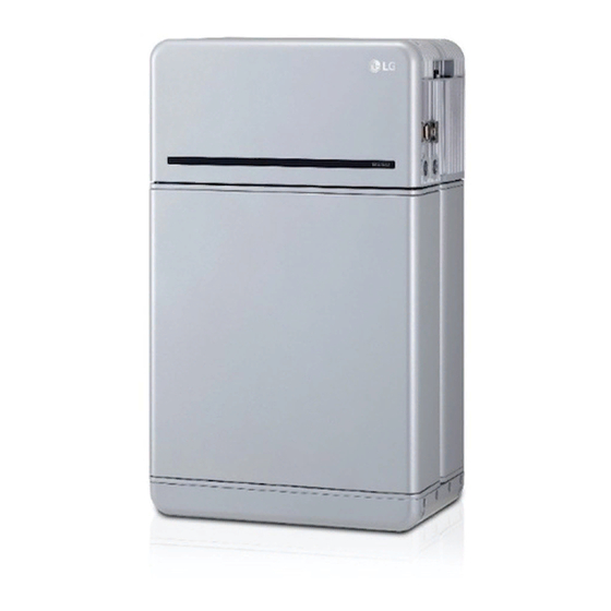
LG RESU16H Prime Installation Manual
Hide thumbs
Also See for RESU16H Prime:
- Installation manual (92 pages) ,
- Installation manual (8 pages) ,
- Installation manual (92 pages)
Table of Contents
Advertisement
Installation Manual for RESU16H Prime
LG Energy Solution strongly advises users to exercise due care in following LG Energy
Solution's product installation manual. Warranty claims are invalid if damage is caused
by human error in a manner inconsistent with the installation manual's instructions.
Scan QR code to view
Scan QR code to view
[Installation Manual PDF File]
[Installation Video Guide]
Version 1.2
Advertisement
Table of Contents

Related Manuals for LG RESU16H Prime


Summary of Contents for LG RESU16H Prime
- Page 1 Installation Manual for RESU16H Prime LG Energy Solution strongly advises users to exercise due care in following LG Energy Solution’s product installation manual. Warranty claims are invalid if damage is caused by human error in a manner inconsistent with the installation manual’s instructions.
-
Page 2: Table Of Contents
6.1.2 Contact Information 3.1.3 Unboxing the Package 7. Appendix 3.1.4 Installation Location 7.1 Connection in RESU16H Prime parallel battery system 3.1.5 Clearance 7.1.1 Setting for communication termination resistor (About Section B) 3.1.6 Tools & Safety Gear Required 7.1.2 Power cable (When using a combiner box) 3.1.7 Appearance and Dimensions... -
Page 3: Safety
Only use the product with a LGES-authorized inverter. Heavy weight may cause serious back injuries For a list of compatible inverters, visit the LG ESS Battery Website by the URL below and check the ‘Home Battery’ > ‘Product Info’ menu. -
Page 4: Warning Label
: Electrical license for battery installation required by the country or state Battery CE / RCM / IEC 62619 / UL1973 / Pack IEC62477-1 Repair the battery by disassembly is possible only at the LG Service Center or by Emissions Class 9 Transportation UN38.3... -
Page 5: Features
2.3 Maintenance 1. Short Circuit Current/Duration Short Circuit Current 1.616 kA RESU16H Prime does not require maintenance during normal operation if properly installed Duration 0.44 ms per the installation manual. In the event of fault, contact the regional service center. -
Page 6: Basic Lifting Guide
3.1.2 Basic lifting guide 4. Pull out the bundled items, including Refer to below guide for lifting and carrying the Battery Control Unit and Battery Modules the Module Connecting Plate. during installation. Handling position Installer A 5. Pull out Battery Module B. Installer B 6. -
Page 7: Clearance
3.1.5 Clearance 3.1.8 System Clearance Recommended clearances for the left, Ceiling right and top of the product are shown in pack and inverter should be in accordance with the installation guide manual of the inverter. 500 mm installer convenience. (20") NOTE An external DC isolator may be installed within the clearance zone. - Page 8 3. Remove the Drill template. Then pre- 7. Remove bubble wrap from Battery Control Unit tighten the fasteners on the Standing connectors of Battery Control Unit Bracket 1. and the warning label of Battery Modules. * The fasteners will be fully tightened Standing bracket 1 Standing bracket_1 in a later step.
- Page 9 11. Check the operation of the battery 15. Loosen 4 bolts and remove the Top pack by following the steps below. Cover. 1) Hold and turn the handle M5xL65 Flange Bolt counterclockwise. 2) Open the front cover and turn on the circuit breaker switch.
- Page 10 20. Open the front cover. 24. Connect the cables according to their application. * Hold the handle and turn it counterclockwise. * Refer to Section 3.3 Cable Connections. Handle Front Cover 25. Arrange the power cables and communication cables separately using cable ties.
- Page 11 3.2.1.3 User Registration 3.2.1.3.1 Visit https://resumonitor.lgensol.com Remote monitoring device (RMD) is a remote device that can install and monitor a battery pack through App. and web. 3.2.1 Prepare for installation using RMD 3.2.1.1 Installer Sign In 3.2.1.1.1 Visit https://resumonitor.lgensol.com 1. Select the “Installer”option. 2.
- Page 12 3.2.2.3 User Agreement 9. Select the “Owner” option. 10. Enter your ID and Password. 1. Search the product which you will install. 11. Click the “Sign In” button. 2. Get the agreement of privacy policy for the customer. 3. If the customer agrees the privacy policy, have customer’s personal information. App.
- Page 13 3.2.2.5 QR Code Scan 3.2.2.6.2 Wi-Fi Connection The QR code scanning method is as follows. If you are using an ethernet connection and do not wish to use Wi-Fi, simply click the “Next” button. Select Prime: Fixed at 2 FLEX: Select from 2 to 4 S/N of consecutive QR codes are automatically displayed(Maximun 5)
- Page 14 3.3 Cable Connections IoT Hub Connection String: Enter the unique string provided to you in order to access the Azure IoT Hub (cloud server). The string format is as follows: HostName=emashub.azure-devices.net;DeviceId=XXXX;SharedAccessKey=OOOO= Section C * For more information on how to obtain strings, refer to Section 3.2.1.2 Obtaining IoT Hub Section A Section B Section D...
- Page 15 4 Commissioning 4. Section E: Battery power port a) Connect the ground wire to Terminal 2. 4.1 LED Indicators b) Connect the negative line of the power cable to Terminal 3. The LED indicators on the front of the battery pack show its operational state as follows: c) Connect the positive line of the power cable to Terminal 1.
- Page 16 6. Contact LG Energy Solution regional service contact point. CAUTION LED Status Action If the battery pack or the inverter indicates FAULT or fails to operate, contact LG Energy Solution regional contact point or your distributor immediately. Power on Charging Visually check if the wiring matches the installation manual.
- Page 17 6 Uninstallation & Return 7. Loosen six (6) M6 bolts and disassemble Standing Bracket #2 6.1 Return/Replacement Instructions Bracket #1 from the wall. 6.1.1 Uninstallation Uninstall the battery pack in the following order: 1. Switch the inverter OFF before beginning uninstallation of the battery 8.
- Page 18 If the battery pack seems to be damaged, contact LG Energy Solution regional contact point or your distributor. Use the contacts below for technical assistance. These phone numbers are available only during business hours on weekdays.
- Page 19 7.2 RMD Applications Inverter How to check the battery status is as follows. ENABLE 12V ENABLE 12V Inverter ENABLE 12V ENABLE 12V ENABLE GND ENABLE GND ENABLE GND ENABLE GND RS485 A+ RS485 A+ RS485 A+ RS485 A+ RS485 B- RS485 B- RS485 B- RS485 B-...
- Page 20 Fault Name error code Support action required Return the battery to LG Over Voltage Fault2 DiagResultFault2 0x0001 Energy Solution. and check the ‘Home Battery Partner’ > ‘Technical Support’ menu. Under Voltage Fault2 DiagResultFault2 0x0002 Battery pack On and check additional errors. In case of normal operation, Charge the First, proceed with RMD Wi-Fi direct connection as shown below.
- Page 21 Can upgrade F/W. Upgrade is performed on the following three targets. 7.2.3.1 User Agreement - RMD Visit https://resumonitor.lgensol.com and Sign in. - BMS - DC/DC 2. Click the ‘Update’ button 3. According to the target you want to update, click the 'Choose File' button. correctly, click the 'Send' button.
- Page 22 Enter the password and click ‘Register’ to go to the home screen. The default password is set to 123456 and can be changed in the Web UI. 1. Server Use: Decide whether to use (connect) to the cloud server. Search and access the SSID of the RMD AP from a device (hereinafter referred to as a device) supporting WLAN Station functions such as a smartphone.
- Page 23 1. Click the Scan AP button on the top right of the Web UI. 2. The number of APs available is displayed in a pop-up window. 3. Select the AP to access from the SSID combo box, enter the password and click the Connect button(Manual input is possible).
- Page 24 Keep this manual for later use. © 2021 LG Energy Solution ESS Battery Division PARC1, 108, Yeoui-daero, Yeongdeungpo-gu, Seoul, Republic of Korea, 07335 https://www.lghomebattery.com http://www.lgensol.com...