
Related Manuals for Motorola IXP-9120


Summary of Contents for Motorola IXP-9120
- Page 1 (217) 352-9330 | Click HERE Find the Emerson / Motorola / Force Computers CPCI-9120 at our website:...
- Page 2 IXP/CPCI-9120 Reference Guide 6806800A77B October 2006...
- Page 3 Printed in the United States of America. Trademarks Motorola® and the stylized M logo are trademarks of Motorola, Inc., registered in the U.S. Patent and Trademark Office. All other names, products, or services mentioned in this document may be trademarks or registered...
- Page 4 Motorola reserves the right to revise this document and to make changes from time to time in the content hereof without obligation of Motorola to notify any person of such revision or changes.
-
Page 6: Table Of Contents
Using this Guide Other Sources of Information Safety Notes Sicherheitshinweise Introduction Features ............33 Standard Compliance . - Page 7 Installation and Removal Procedure ..........48 LA1-920/8M .
- Page 8 DDR Controller ............. . . 84 QDR SRAM Interface .
- Page 9 Register Details ........... 103 General Purpose EPLD .
- Page 10 RedBoot Commands ..........123 Common Commands .
- Page 11 IXP/CPCI-9120...
- Page 12 Table 1 Organization of this Manual ..........15 Introduction Table 1 Ordering Information Excerpt: RoHS Part Number .
- Page 13 Table 33 Interrupt Status Register-3 ..........112 Table 34 I2C MUX Reset Register .
- Page 14 Introduction Figure 1 Single Slot Complex Functional Block Diagram change to Single NPU ..33 Installation Figure 2 Location of Switches ..........49 Figure 3 Inserting the Bezel of the PMC into the Cutout on the Front Panel .
- Page 15 Diagnostics Troubleshooting IXP/CPCI-9120...
- Page 16 Using this Guide This Reference Guide is intended for users qualified in electronics or electrical engineering. Users must have a working understanding of Peripheral Component Interconnect (PCI), Com- pact Peripheral Component Interconnect (CPCI), and telecommunications. Organization of this Manual The Reference Guide is organized as follows. Table 1: Organization of this Manual Chapter Description...
- Page 17 Conventions Notation Description All numbers are decimal numbers except when used with the notations described below 00000000 Typical notation for hexadecimal numbers (digits are 0 through F), e.g. used for addresses and offsets 0000 Same for binary numbers (digits are 0 and 1) Generic use of a letter Generic use of numbers 0.75...
- Page 18 Notation Description No danger encountered. Pay attention to important information marked using this Note: layout Caution Possibly dangerous situation: slight injuries to people or damage to objects possible Danger Dangerous situation: injuries to people or severe damage to objects possible Abbreviations Board Information Block Baseboard Management Controller...
- Page 19 Interrupt Request Internet Exchange Processor JTAG Joint Test Actions Group Keyboard Controller Style LA-1 Look Aside Phase 1 Linear Feet per Minute LVTTL Low Voltage Transistor-Transistor Logic Media Access Controller Media Independent Interface MMSC Microprocessor and Microcomputer Standards Committee Media Switch Fabric Not Applicable Network Interface Card Network Processor Unit...
- Page 20 Rear Transition Board Software Development Kit SDRAM Synchronous Dynamic Random Access Memory Small Form Pluggable SONET Synchronous Optical Network Serial Presence Detect SPI3 System Packet Interface Level 3 SRAM Static Random Access Memory SREC S Record SSRAM Synchronous Static Random Access Memory SSTL_2 Stub Series Terminated logic for 2.5 Volts To Be Decided...
- Page 21 Revision Date Description 6806800A77 June 2006 Updated with Motorola logo; formatted RedBoot commands; change and update in Part Numbers in Ordering Information and Accessories; name change to IXP/CPCI-9120; RoHS compliance added to Standards table; block diagrams updated. This manual has the new Part Number.
- Page 22 Other Sources of Information For further information refer to the following documents: Company www. Document Altera altera.com MAX 7000A programmable Logic Device Family Altera altera.com MAX 3000A programmable Logic Device Family Intel intel.com Intel® IXF1104 4-Port Gigabit EthernetMedia Access Controller Revision Number: 006 Revision Date: August 21, 2003 Intel...
- Page 23 Company www. Document VITA Standards vita.com Processor PMC Standard, Organisation VITA 32 Draft 1.0a (VSO) Vitesse vitesse.com VSC215 Baseboard Management Controller Data Manual, Version 0.56, JAN/11/2001 IXP/CPCI-9120...
-
Page 24: Safety Notes
The board has been tested in a standard Motorola ECC system and found to comply with the limits for a Class A digital device in this system, pursuant to part 15 of the FCC Rules respectively EN 55022 Class A. - Page 25 Installation Electrostatic discharge and incorrect board installation and removal can damage cir- cuits or shorten their life. Therefore: • Before installing or removing the board, read see “Action Plan” page -41. • Before touching boards or electronic components, make sure that you are working in an ESD-safe environment.
- Page 26 Replacement/Expansion Only replace or expand components or system parts with those recommended by Motor- ola ECC. Otherwise, you are fully responsible for the impact on EMC and the possibly changed functionality of the product. Check the total power consumption of all components installed (see the technical specifi- cation of the respective components).
- Page 27 IXP/CPCI-9120...
-
Page 28: Sicherheitshinweise
Anwendungen in der Telekommunikationsindustrie und im Zusammenhang mit Industriesteuerungen verwendet werden. Einbau, Wartung und Betrieb dürfen nur von durch Motorola ECC ausgebildetem oder im Bereich Elektronik oder Elektrotechnik qualifiziertem Personal durchgeführt werden. Die in diesem Handbuch enthaltenen Informationen dienen ausschließlich dazu, das Wissen von Fachpersonal zu ergänzen, können es aber in keinem Fall ersetzen. - Page 29 Installation Elektrostatische Entladung und unsachgemäßer Ein- und Ausbau des Boards kann Schaltkreise beschädigen oder ihre Lebensdauer verkürzen. Beachten Sie deshalb die folgenden Punkte: • Lesen sie vor Ein- oder Ausbau des Boards den Abschnitt “Action Plan” auf Seite 2- 41" •...
- Page 30 Stellen Sie sicher, dass Anschlüsse und Kabel des Boards während des Betriebs nicht berührt werden können. Austausch/Erweiterung Verwenden Sie bei Austausch oder Erweiterung nur von Motorola ECC empfohlene Komponenten und Systemteile. Andernfalls sind Sie für mögliche Auswirkungen auf EMV und geänderte Funktionalität des Produktes voll verantwortlich.
-
Page 32: Introduction
Introduction... -
Page 34: Features
Introduction Features Features IXP/CPCI-9120 is a 6U 4HP CompactPCI Single Board Computer complex based on the Intel IXP2400 network processor for up to duplex OC-48 or 4 Gbit Ethernet bandwidth applica- tions. IXP/CPCI-9120 has a Processor PMC expansion for expandable Control plane process- ing power, a flexible media interface mezzanine to support different standard and OEM media flavors (e.g., Copper Ethernet, Fiber Ethernet, SONET/ATM, DS1/E1, etc.), and a SRAM expansion mezzanine site for memory expansion or co-processing support. - Page 35 Features Introduction The 2.16 variant provides two Gigabit Ethernet ports on the PICMG 2.16 links. IXP/CPCI-9120 single slot board complex comprises of the following features: • Single-NPU Intel IXP2400 board at 600 MHz • 256 MB SO-DIMM DDRSDRAM with ECC •...
-
Page 36: Standard Compliance
The IXP/CPCI-9120 and all sub-boards meet the following standards: Standard Description EN 60950-1 Legal safety requirements UL 60950-1 CSA 60950-1 60950-1 (in a predefined Motorola sys- EN 55022 EMC requirements on system level tem) EN 55024 EN 300 386 FCC part 15 CISPR 22... -
Page 37: Ordering Information
Ordering Information Introduction Ordering Information When ordering the IXP/CPCI-9120 board variants, upgrades and accessories, use the order numbers given below. Product Nomenclature In the following you find the key for the product name extensions. IXP/CPCI-9120/xxx/ccc/Lyyy/zz SO-DIMM DDRSDRAM size in Mbyte QDRSRAM size in Mbyte Lyyy QDRSRAM size in Mbyte on LA-1 mezzanine card... - Page 38 Introduction Ordering Information Table 2: Ordering Information Excerpt: Non RoHS Part Number Order No. IXP/CPCI-9120 Description Hardware Accessories IXP/CPCI-9120 111013 ACC/Serial/Cable/MD9/RD9/2 MD9 to DB9 Serial cable Note: The Serial cable is used only for debug purpose. 120460 ACC/Serial Cable DTE 214451 CABLE, 9 Rnd Shielded IXP/CPCI-9120...
- Page 39 Ordering Information Introduction IXP/CPCI-9120...
-
Page 40: Installation
Installation... -
Page 42: Action Plan
Installation Action Plan Action Plan To install the board, the following steps are necessary and described in detail in the sections of this chapter. B egin Installation Take A nti-S tatic Precautions U npack Kit C ontents C heck K it C ontents C heck P hysical R equirem ents C heck E nvironm ental... -
Page 43: Preparing For Installation
Preparing for Installation Installation Preparing for Installation Prepare for installation by following these steps: • Take Antistatic Precautions • Unpacking Kit Contents • Environmental Requirements • Power Requirements Take Antistatic Precautions When handling circuit boards and associated internal computer components, use an antistatic wristwrap or wear isolation gloves. -
Page 44: Accessories
Installation Preparing for Installation Note: Do not discard the original packaging material in case a factory return is necessary. Accessories The following table lists the accessories available for IXP/CPCI-9120. Table 3: Accessories: RoHS compliant ACC/Serial/Cable/MD9/RD9/25E 122753 ACC/Serial Port Y-Adapter/5E 122734 Note: The Serial cable is used only for debug purpose. -
Page 45: Requirements
Requirements Installation Requirements To meet the environmental requirements, the IXP/CPCI-9120 has to be tested in the system where it is to be installed. Before you power up the board, calculate the power needed accord- ing to your combination of board upgrades and accessories. Environmental Requirements The environmental values must be tested and proven in the used system configuration. - Page 46 Installation Requirements Table 5: Environmental Requirements Feature Operating Non-Operating Shock Shape: Half sine Shape:half sine Acceleration:5g Accelaration:15g Duration:2ms Duration: 11ms Number of shocks: 3 per direction (6 Number of shocks: 3 per direction (6 per per axis) total of 18 shocks axis) total of 18 shocks Free Fall 100 mm/3 axis...
-
Page 47: Power Requirements
Requirements Installation Power Requirements The board’s power requirements depend on the installed hardware accessories. The following table gives examples of maximum power requirements for 5V and 3.3V for a processor run- ning at 600 MHz without any PMC card installed. If you want to install any accessories, the load of the respective accessory has to be added to the load of the used board variant. -
Page 48: Hardware Upgrades And Accessories
Installation Hardware Upgrades and Accessories Hardware Upgrades and Accessories The IXP/CPCI-9120 itself allows an easy and cost-efficient way to adapt the system board to your application needs. IO Daughtercard The MSF mezzanine connects to the MSF interface of the IXP2400. Several flavors are planned, thereby providing added expansion and flexibility. -
Page 49: Installation And Removal Procedure
Hardware Upgrades and Accessories Installation Installation and Removal Procedure For details on how to install and remove PMC, see “Installing PMC” and see “Removing PMC” page -53. LA1-920/8M LA1-920/8M is a QDR SRAM memory expansion mezzanine that is connected to Channel 1 of the IXP2400 memory controller. -
Page 50: Switch Settings
Installation Switch Settings Switch Settings Single Throw Single pole switches are provided on the IXP/CPCI-9120 to • Accord Monarch status to the PrPMC • Force BMC or PM mode of operation for the IPMI controller • Disable reset of the system from the Front panel •... -
Page 51: Installing Pmc
Switch Settings Installation Table 7: Switch settings (cont.) Switch Position Description OFF: Front Panel Reset enable ON: Front Panel Reset disable OFF: PrPMC Monarch disable ON: PrPMC Monarch enable OFF: Auto-detect (BMC or PM mode) ON: Force BMC mode OFF: Depends on Switch position 3 ON: Force PM Note: Positions 3 and 4 of SW3 are used together as indicated in Table 6. - Page 52 Installation Switch Settings 5. Insert the bezel of the PMC into the cutout on the front panel as shown in Figure 3. Figure 3: Inserting the Bezel of the PMC into the Cutout on the Front Panel 6. Engage the connectors as shown in Figure 4 making sure they are seated com- pletely.
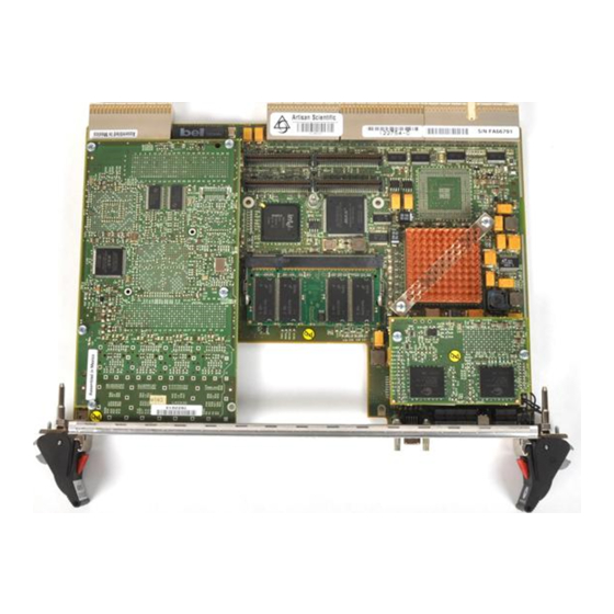
- Page 53 Switch Settings Installation Figure 5: Securing the PMC using Screws provided Installation of the PMC on IXP/CPCI-9120 is now complete. A view of the IXP/CPCI-9120 with the installed PMC is shown in Figure 6. Figure 6: IXP/CPCI-9120 with the installed PMC Note: Ensure that you cover the unused FrontPanel cutouts with filler panels.
-
Page 54: Removing Pmc
Installation Switch Settings Removing PMC To remove the PMC from IXP/CPCI-9120 follow the steps detailed here: 1. Turn off system power. 2. Remove IXP/CPCI-9120 from the system as per the removal procedure detailed in section “Installation in a Non-Powered System”. 3. -
Page 55: Ixp/Cpci-9120 Board Installation
IXP/CPCI-9120 Board Installation Installation IXP/CPCI-9120 Board Installation The I provides hot-swap support and hence may be installed in or removed from XP/CPCI-9120 a powered system. This section details installation of IXP/CPCI-9120 in a non-powered sys- tem and in a powered system supporting hot-swap. Installation in a Non-Powered System Installation Procedure In order to install the board in a non-powered system, proceed as follows:... - Page 56 Installation IXP/CPCI-9120 Board Installation Figure 7: Top and bottom Injector/Ejector Handles in the outward position 4. Check that the top and bottom injector/ejector handles are in the outward position as shown by arrows in Figure 7. 5. Slide the board into the chassis until you feel resistance (approximately 1/4 inch short of full insertion).
- Page 57 IXP/CPCI-9120 Board Installation Installation Figure 8: Installing Board -- Slide Board into Chassis 6. Simultaneously move the top and bottom injector/ejector handles to the inward position. 7. Verify that the board is seated properly. 8. Tighten the handle screws that secure the board to the chassis. A zoomed view of the screw on the injector/ejector handle is shown in Figure 9.
-
Page 58: Removal Procedure
Installation IXP/CPCI-9120 Board Installation Removal Procedure In order to remove a board from a non-powered system, proceed as follows: 1. Turn off system power. 2. Unfasten screws of front panel until board is detached from rack frame. 3. Press the red button on the ejector/injector handles. 4. -
Page 59: Installation In Basic Hot Swap System
IXP/CPCI-9120 Board Installation Installation Installation Procedure Before installing IXP/CPCI-9120, observe the following: Caution Only install the board under hot-swap conditions if the board is to be operated in slots for which hot swap is explicitly permitted by the system documentation (in most hot- swap systems, only Peripheral Slots are hot-swappable). -
Page 60: Installation In Full Hot-Swap System
Installation IXP/CPCI-9120 Board Installation Installation in Full Hot-Swap System In order to install the board in a full hot-swap system proceed as follows: 1. Ensure that the board has the desired accessories and that all switches are appropri- ately configured. 2. -
Page 61: Removal From Full Hot-Swap System
IXP/CPCI-9120 Board Installation Installation Removal from Full Hot-Swap System To remove the board from a full hot-swap system, proceed as follows: 1. Press red buttons on ejector/injector handles to indicate board removal. 2. Wait until blue hot-swap LED is illuminated. 3. -
Page 62: Controls, Indicators And Connectors
Controls, Indicators and Connectors... -
Page 64: Front Panel
Controls, Indicators and Connectors Front Panel Front Panel An IEEE 1101.10-compliant front panel is used on the IXP/CPCI-9120. The front panels are equipped with an EMC gasket and two ejector/injector handles. The front panel accommodates the following: • Hot swap status LED (Blue LED) placed above the lower ejector. •... - Page 65 Front Panel Controls, Indicators and Connectors Figure 10: Front Panel of IXP/CPCI-9120 see following page. Description of IO Interfaces, Switches and LEDs on Front Panel, Table 9: Description of IO Interfaces, Switches and LEDs Cut-out for PMC module COM1 D-type subminiature D-type connector Ethernet Port1 Bi-color LED Ethernet Port2 Bi-color LED IXP/CPCI-9120...
-
Page 66: Leds
Controls, Indicators and Connectors Front Panel Table 9: Description of IO Interfaces, Switches and LEDs Ethernet Port3 Bi-color LED Ethernet Port4 Bi-color LED RESET Reset Switch User defined Bi-color LED Hot swap status LED Power Status Bi-color LED LEDs The following indicators are provided on the front panel of the IXP/CPCI-9120: Table 10: Description of Front Panel LEDs Description Hot Swap... -
Page 67: Keys
Front Panel Controls, Indicators and Connectors Table 10: Description of Front Panel LEDs Description Green Link OK Yellow Collision Keys Front Panel Reset A pinhole reset switch is provided on the front panel. Pressing this switch causes all devices on the IXP/CPCI-9120 to reset except IBMU. This reset will be active as long as the reset switch is held in the active position. -
Page 68: On-Board Connectors
Controls, Indicators and Connectors Front Panel On-Board Connectors IXP/CPCI-9120 has the following on-board connectors: • CompactPCI connectors • PrPMC connectors • MSF mezanine connector • LA-1 mezzanine connector CompactPCI Connectors CompactPCI connectors J1, J2, J3, and J5 are present. J1 and J2 The J1 and J2 CompactPCI connectors implement the CompactPCI 64 bit connector pinouts as specified by the CompactPCI specification. -
Page 69: Prpmc Connectors
Front Panel Controls, Indicators and Connectors Note: J4 connector is not mounted. Figure 13: J5 Connector Pinout (rows A-E) Note: All pins of Row F are taken to GND. PrPMC Connectors PMC slot connectors include the following: • Jn1 and Jn2 for the 32-bit PCI bus signals •... -
Page 70: Msf Mezzanine Connector
Controls, Indicators and Connectors Front Panel Figure 14: Jn4 Connector Pinout MSF Mezzanine Connector Two 400-pin MEG-Array® connectors from FCI are used to connect the baseboard with the MSF mezzanine card. One connector contains all MSF, C-bus, LED signals and Power sig- nals. - Page 71 Front Panel Controls, Indicators and Connectors Figure 15: MSF Mezzanine Connector Pinout (rows A-C). IXP/CPCI-9120...
- Page 72 Controls, Indicators and Connectors Front Panel Figure 16: MSF Mezzanine Connector Pinout (rows D-E) IXP/CPCI-9120...
- Page 73 Front Panel Controls, Indicators and Connectors Figure 17: MSF Mezzanine Connector Pinout (rows F-H) IXP/CPCI-9120...
- Page 74 Controls, Indicators and Connectors Front Panel Figure 18: MSF Mezzanine Connector Pinout (rows J-K) IXP/CPCI-9120...
- Page 75 Front Panel Controls, Indicators and Connectors Figure 19: MSF Mezzanine Connector Pinout (MDI, SlowPort, I2C and JTAG) rows A-C IXP/CPCI-9120...
- Page 76 Controls, Indicators and Connectors Front Panel Figure 20: MSF Mezzanine Connector Pinout (MDI, SlowPort, I2C and JTAG) rows D-E IXP/CPCI-9120...
- Page 77 Front Panel Controls, Indicators and Connectors Figure 21: MSF Mezzanine Connector Pinout (MDI, SlowPort, I2C and JTAG) rows F-H IXP/CPCI-9120...
-
Page 78: La-1 Mezzanine Connector
Controls, Indicators and Connectors Front Panel Figure 22: MSF Mezzanine Connector Pinout (MDI, SlowPort, I2C and JTAG) rows J-K Note: Rows B, D, F, H and K are Ground. LA-1 Mezzanine Connector A 200-pin MEG-Array® connector from FCI is used to connect the QDR II Channel 1 inter- face of the IXP2400 to the LA-1 mezzanine card. - Page 79 Front Panel Controls, Indicators and Connectors Figure 23: LA-1 Pinout rows A-C Figure 24: LA-1 Pinout rows D-E IXP/CPCI-9120...
- Page 80 Controls, Indicators and Connectors Front Panel Figure 25: LA-1 Pinout rows F-H Figure 26: LA-1 Pinout rows J-K IXP/CPCI-9120...
- Page 81 Front Panel Controls, Indicators and Connectors IXP/CPCI-9120...
-
Page 82: Devices' Features And Data Paths
Devices’ features and Data Paths... -
Page 84: Block Diagram
Devices’ features and Data Paths Block Diagram Block Diagram BOOT ROM IBMU USER FLASH Flash Demultiplexed SlowPort bus EPLD MSF MEZZANINE SITE IO-920/4GBE-T/P SlowPort EPLD EPLD Slow Port SO-DIMM (Up to 512 MB) QDR II SSRAM Ch 0 (Up to 16 MB) RGMII IXP2400 RGMII... -
Page 85: Pci Controller
Block Diagram Devices’ features and Data Paths • Two unidirectional 32-bit LVTTL media interfaces (Rx and Tx) programmable to be SPI- 3, UTOPIA 1/2/3 or CSIXL1. Each path is configured for 4x8 bit, 2x16 bit, 1x32 bit or combinations of 8 and 16 bit data paths. •... -
Page 86: Serial Port
Devices’ features and Data Paths Block Diagram CSIX standard is a source-synchronous bus, the IXP2400 uses a common-clocking scheme for compatibility with the other protocols. The MSF interface on IXP/CPCI-9120 is connected to a mezzanine card. Serial Port The IXP2400 contains a standard RS-232–compatible universal asynchronous receiver/trans- mitter (UART), which can be used for communication with a debugger or maintenance con- sole. -
Page 87: Pci Bus Signaling On The Compactpci Bus
IBMU System management functionality as described in PCIMG 2.9 R1.0 is achieved through the Motorola GmbH IBMU building block (R1.2). IBMU is a functional unit that provides remote sensing and remote management functionality according to the IPMI specification v1.0. -
Page 88: Icmb
Devices’ features and Data Paths Block Diagram IBMU runs totally independent of the IXP2400, its main task being monitoring and logging of events. IBMU shall be fully functional even when the IXP/CPCI-9120 is not powered. IBMU is mapped on to IXP2400’s SlowPort area. Communication between the IPMI control- ler and the IXP2400 is achieved through the General Purpose EPLD, which translates slow- port signals into X-bus and vice versa. - Page 89 Block Diagram Devices’ features and Data Paths IXP/CPCI-9120...
-
Page 90: Daughter Card Details
Daughter Card Details... -
Page 92: Media Switch Fabric Mezzanine
Daughter Card Details Media Switch Fabric mezzanine Media Switch Fabric mezzanine The MSF mezzanine connects to the MSF interface of the IXP2400. Several flavors are planned, thereby providing added expansion and flexibility. IO-920 IO-920 MSF Mezzanine card is designed for use in Single Slot complex board. The IO-920 accommodates an Intel®... -
Page 93: Io-920 Variants
IO-920 Variants The IO-920 also houses an I/O connector through which MDI lines from the dual gigabit eth- ernet controller are brought into the IO-920. Through multiplexers and demultiplexers, signals from the on-board PHY and the baseboard Dual MAC (82546GB) can either be routed to the PSB . -
Page 94: La-1/Qdr Mezzanine
Daughter Card Details LA-1/QDR mezzanine LA-1/QDR mezzanine The IXP2400 has two independent SRAM controllers, each of which supports pipelined QDR SSRAM and/or a coprocessor that adheres to QDR signaling. One of the two QDR SRAM interfaces of the IXP2400 is used to provide 8 MB of on-board QDR II SRAM, while the other is connected to an expansion slot through a 200-pin MEG- Array®... -
Page 96: Maps And Registers
Maps and Registers... -
Page 98: Pci Memory Map
Maps and Registers PCI memory map PCI memory map Table 11: PCI Memory Map PCI device Description IDSEL Device number 82546GB Dual LAN controller PrPMC First PCI agent of the PrPMC PrPMC Second PCI agent of the PrPMC IXP2400 IXP/CPCI-9120... -
Page 99: Slowport Map
SlowPort map Table 12: SlowPort Map Device SlowPort Address Description Flash BootROM Flash C400 0000 – C5FF FFFF User Flash C400 0000 – C5FF FFFF General purpose EPLD Variant ID C600 0000 Indicates base board type. Version No. C600 0001 EPLD version number Board Revision No. - Page 100 Maps and Registers SlowPort map Table 12: SlowPort Map Device SlowPort Address Description Watchdog Timer C600 00A0 Clears the Watchdog Timer interrupt. Interrupt Clear Register Watchdog Enable and C60000B0 Enable/Disable the watchdog and Watchdog Reset Enable watchdog interrupt to reset the board Register Watchdog Time Set Regis- C60000C0...
- Page 101 Table 12: SlowPort Map Device SlowPort Address Description Interrupt Mask Register C700 000B Provides the ability to mask inter- rupts generated by the PHY and Interrupt Status Register C700 000F Provides status of interrupts issued by the PHY and MAC SlowPort addresses for the MAC are derived from the MAC offsets by multiplying the offset by 4 and adding the result to C600 4000.
-
Page 102: I2C Memory Map
Maps and Registers I2C memory map I2C memory map NPU I2C memory map Table 13: NPU I2C Memory Map Device Description I2C Address Real Time Clock SO-DIMM SPD SO-DIMM on IXP/CPCI-9120 MSF EEPROM EEPROM I2C MUX Multiplexer for RTC LA-1 site LA-1 on IXP/CPCI-9120 PrPMC site PrPMC site... -
Page 103: Sense I2C Memory Map
SENSE I2C memory map Table 14: SENSE I2C Memory Map Device Description I2C Address LM87 Voltage/Temperature sensor on IXP/CPCI-9120 BIB I2C Memory Map Table 15: BIB I2C Memory Map Device Description I2C Address 24LC128 Board BIB AT24C02 IBMU BIB... -
Page 104: Register Details
Maps and Registers Register Details Register Details General Purpose EPLD Variant ID Address: C600 0000 Type: Read only This register uniquely identifies the board as IXP/CPCI-9120 and also indicates the amount of on-board QDR II SSRAM installed. Table 16: Variant ID Description Access 00: 8 MB on-board QDR II SSRAM... -
Page 105: Board Revision Number
Board Revision Number Address: C600 0002 Type: Read only This register indicates the board revision number. Table 18: General Purpose EPLD-Board Revision Number Description Access Board revision number User Flash Select Address: C600 0003 Type: Read/Write User Flash and BootROM Flash is mapped in the same area of memory. This register enables either type to be selected. -
Page 106: Prpmc Register
Maps and Registers Register Details Table 20: CompactPCI Register Description Access 0: PCI Present 1: PCI not present 0: Hot Swap Eject Switch Open 1: Hot Swap Eject Switch Closed 0: Blue LED Off 1: Blue LED On Reset value: 1 PrPMC register Address: C600 0020 Type: Read/Write... -
Page 107: User Led Control Register
Type: Read Only System-specific configurations are indicated here. Table 22: System Specific Register Description Access 0: PrPMC Mezzanine Card Present 1: PrPMC Mezzanine Card Absent 0: Reserved 1: Reserved 0: MSF Mezzanine Card Present 1: MSF Mezzanine Card Absent 0: LA1 Mezzanine Card Present 1: LA1 Mezzanine Card Absent User LED Control register Address: C600 0050... -
Page 108: Watchdog Timer Register
Maps and Registers Register Details Watchdog Timer Register Address: C600 0090 Type: Write Only This register must be accessed periodically (refreshed). Failure to access this register results in an interrupt. Failure to refresh this register after an interrupt has been issued will result in a reset of the entire system. -
Page 109: Watchdog Time Set Register
Watchdog Time Set Register Address: C600 00C0 Type: Read/Write This register provides a means to select the refresh time of the watchdog timer. Table 27: Watchdog Time Set Register Description Access 111: Refresh Time of 2 secs 110: Refresh Time of 3 secs 101: Refresh Time of 4 secs 100: Refresh Time of 5 secs 011: Refresh Time of 6 secs... -
Page 110: Interrupt Mask Register-2
Maps and Registers Register Details Table 28: Interrupt Mask Register-1 Description Access 0: IPMI Interrupt-0 is not masked 1: IPMI Interrupt-0 is masked Reset value: 1 0: 82546 Interrupt-B is not masked 1: 82546 Interrupt-B is masked Reset value: 1 0: 82546 Interrupt-A is not masked 1: 82546 Interrupt-A is masked Reset value: 1... -
Page 111: Interrupt Mask Register-3
Table 29: Interrupt Mask Register-2 Description Access 0: RFU 1: RFU 0: RFU 1: RFU Reset value: 1 Interrupt Mask Register-3 Address: C700 000A Type: R/W Interrupts can be masked through the Interrupt mask registers. All interrupts are masked on reset/power-on. -
Page 112: Interrupt Status Register-2
Maps and Registers Register Details Table 31: Interrupt Status Register-1 Description Access 0: Reserved 1: Reserved 0: MSF Interrupt is active 1: MSF Interrupt is not active 0: LA1 Interrupt is active 1: LA1 Interrupt is not active 0: IPMI Interrupt-2 is active 1: IPMI Interrupt-2 is not active 0: IPMI Interrupt-1 is active 1: IPMI Interrupt-1 is not active... -
Page 113: Interrupt Status Register-3
Table 32: Interrupt Status Register-2 Description Access Interrupt Status Register-3 Address: C700 000E Type: Read Only This register provides Interrupt status. When interrupted, the NPU can interrogate the three Interrupt status registers to determine the interrupt-source. Table 33: Interrupt Status Register-3 Description Access 0: Ejector handles are open... -
Page 114: Mac Epld-Io-920
Maps and Registers Register Details MAC EPLD-IO-920 Registers of the EPLD in IO-920 are described below. Variant ID Address: C600 3010 Type: Read only This register provides information on the board variant. Table 35: MAC EPLD - IO-920-Variant ID Description Access 0000: IO-920 (Front variant) 0001: IO-920 (Rear variant) -
Page 115: Phy Reset Control Register
Figure 29: Board revision Number Description Access Board Revision number for the current board PHY Reset Control Register Address: C600 3020 Type: Read/Write This register provides a means of controlling PHY operation. The PHY can be held in reset until the OS is ready to initialize the PHY. This delayed reset is useful in cases where it is nec- essary to prevent link-pulses from being sent on the line before the OS has booted (Example: Rev C0 silicon of Marvell’s 88E1145). -
Page 116: Mac Pause Address Register
Maps and Registers Register Details MAC PAUSE Address Register Address: C600 3050 Type: Read/Write This register provides a means of selecting the port on to which XON or XOFF packets must be transmitted. Table 37: MAC PAUSE Address Register Description Access 000: XON Packet, on all IXF1104 Ports 001: XOFF Packet, on Port-0... -
Page 117: Interrupt Status Register
Table 39: Interrupt Mask Register Description Access 0: PHY Port-3 Interrupt is not masked 1: PHY Port-3 Interrupt is masked Reset value: 1 0: PHY Port-2 Interrupt is not masked 1: PHY Port-2 Interrupt is masked Reset value: 1 0: PHY Port-1 Interrupt is not masked 1: PHY Port-1 Interrupt is not active Reset value: 1 0: PHY Port-0 Interrupt is not masked... -
Page 118: Redboot
RedBoot... -
Page 120: Action Plan
RedBoot Action Plan Action Plan IXP/CPCI-9120... -
Page 121: Introduction
Introduction RedBoot Introduction This chapter details the RedBoot firmware that runs on the IXP 2400 processor on the IXP/CPCI-9120 board. This chapter also details the commands that are supported by the firmware. The main purpose of RedBoot for IXP/CPCI-9120 is to boot VxWorks, Diagnostics, and Linux. -
Page 122: Building Images
RedBoot Building Images Building Images 1. Create a folder RedBoot and untar the source file frcCPCI920_RedBoot_SRC_Rel_<x_x>.tar into RedBoot folder. 2. Verify whether a directory named SOURCES has been created. 3. The tool chain for building RedBoot can be downloaded from the following link: http://public.planetmirror.com/pub/redhat-gnupro/dev_tools/010413/ http://sunsite.rediris.es/sites/download.intel.nl/design/intelxscale/dev_tools/010413/ The file to be downloaded is i686-pc-linux-gnulibc2.1-x-xscale-elf.tar.Z. -
Page 123: Loading Images From Redboot
Loading Images from RedBoot RedBoot Loading Images from RedBoot RedBoot 1. Execute boot_flash command to switch to boot flash. RedBoot> boot_flash 2. Load the redboot.bin image to SDRAM using load command RedBoot> load redboot.bin -b 0x400000 3. Unlock the boot flash from 0xC40000000 to 0xC4040000 using fis unlock command RedBoot>... -
Page 124: Redboot Commands
RedBoot RedBoot Commands RedBoot Commands This section details the commands available in RedBoot. Common Commands The general format of commands is: command <options, parameters> Numbers, such as a memory location, may be specified in either decimal or hexadecimal (requires a 0x prefix). ping YNTAX ping [-v] [-n <count>] [-l <length>] [-t <timeouts>] [-r <rate>][-i... - Page 125 RedBoot Commands RedBoot Cache Settings YNTAX cache [ON | OFF] DESCRIPTION This command is used to manipulate the caches on the processor. With no options, this com- mand specifies the state of the system caches. When an option is given, the caches are turned off or on appropriately.
- Page 126 RedBoot RedBoot Commands boot_flash YNTAX boot_flash DESCRIPTION This command is used to switch to boot flash RedBoot>boot_flash user_flash YNTAX user_flash DESCRIPTION This command is used to switch to user flash RedBoot>user_flash help YNTAX help [<topic>] DESCRIPTION This command is used for help. Detect I2C devices YNTAX i2cdetect...
- Page 127 RedBoot Commands RedBoot Write into I2C device YNTAX write [slave address] [offset] [data] DESCRIPTION Write into I2C for the specified slave address and offset. Data field should be a continous hexadecimal string to write into I2C device. RedBoot> i2c_write 0xa4 0 555555 RedBoot>...
- Page 128 RedBoot RedBoot Commands Read word YNTAX inw [address] DESCRIPTION This command reads the value of the word at [address]. inl 0xc4000000 RedBoot> 0xfefe RedBoot> Read IPMI info YNTAX ipmi [netfn] [command] [lun] <data> DESCRIPTION This command reads the IPMI info for the specified netfn, cmd, lun Data field is optional and depends on IPMI command.
- Page 129 RedBoot Commands RedBoot Write Word YNTAX outw [address] [value] DESCRIPTION This command writes value to word address. outw 0xc6000000 0x0 RedBoot> Read PCI config registers YNTAX config read [-b <bus>] [-d <device>] [-f <func>] [-r <reg>] DESCRIPTION This command reads the PCI Configuration Register for the specified values of the bus num- ber, device number, function and the register number.
- Page 130 RedBoot RedBoot Commands Display PCI device Info YNTAX device show [-b <bus>] [-d <device>] [-f <func>] DESCRIPTION This command shows all configuration registers for the PCI device for the given bus number, device number and function number. RedBoot> pci_device_show -b 0 -d 2 -f 0 PCI Device Configuration Header: (0x00) PCI device and vendor IDs: 0x12298086...
- Page 131 RedBoot Commands RedBoot DESCRIPTION The command stores the MAC address of the backplane ethernet controller into the flash. The command should be followed by the program_eeprom command that stores the MAC address into the EEPROM of 82546. RedBoot>mac_prog 0xbe 0xba 0xbe 0xba 0xbe 0xba ...
- Page 132 RedBoot RedBoot Commands FLASH(16M): 0xc4000000 - 0xc5000000, 128 blocks of 0x00020000 bytes each. Base Board Rev: 0 Base Board EPLD Rev: 2 IO-920 BOARD Rev: 10 IO-920 EPLD Rev: 2 82546_backplane YNTAX 82546_backplane DESCRIPTION This command is used to have control plane connectivity to the back plane. RedBoot>...
-
Page 133: Download Process
Download Process RedBoot Download Process load YNTAX load {file} [-v] [-b location] [-r] [-m {[xmodem]|[ymodem]|[tftp]} ] [-h host_IP_address] DESCRIPTION The load command is used to download data into the target system. Data can be loaded via a network connection, using either the TFTP protocol, or the console serial connection using the X/Y modem protocol. -
Page 134: Flash Image System (Fis)
RedBoot Flash Image System (FIS) Flash Image System (FIS) Executable images, as well as data, can be stored in flash in a simple file store. The com- mand is used to manipulate and maintain flash images. The available commands are: YNTAX fis init [-f] DESCRIPTION... -
Page 135: Arguments
Flash Image System (FIS) RedBoot YNTAX fis free DESCRIPTION This command shows which areas of the flash memory are currently not in use. ‘In use’ means that the block contains non-erased contents. Since it is possible to force an image to be loaded at a particular flash location, this command can be used to check whether that location is in use by any other image. -
Page 136: Arguments
RedBoot Flash Image System (FIS) Note: By using this option it is possible to create a completely empty flash image, for ex- ample to reserve space for use by applications other than RedBoot. : Only if is specified, the FIS directory is updated, and no data is copied from RAM to flash. - Page 137 Flash Image System (FIS) RedBoot : Compute and print the checksum of the image data after it has been loaded into mem- ory. : Decompress gzipped image while copying it from flash to RAM. RedBoot> fis load Diag RedBoot> go YNTAX fis delete name DESCRIPTION...
- Page 138 RedBoot Flash Image System (FIS) YNTAX fis write -b <location> -l <length> -f <flash addr> DESCRIPTION Writes data from RAM at <location> to flash. RedBoot> load -r -b 0x400000 -h 10.208.32.68 vxWorks.st_rom.bin Raw file loaded 0x00400000-0x0049e530 RedBoot> RedBoot> fis write -f 0xc4200000 -b 0x400000 -l 0x100000 * CAUTION * about to program FLASH at 0xc4200000..0xc42fffff from 0x00400000 - are you sure (y/n)? y Make sure flash is unlocked...
- Page 139 Flash Image System (FIS) RedBoot -l - The configuration data is simply listed. Example RedBoot> fconfig -l Run script at boot: false Use BOOTP for network configuration: false Local IP address: 10.208.33.99 Default server IP address: 10.208.33.50 Network debug: false Default network device: i82546_gb2 RedBoot>...
- Page 140 RedBoot Flash Image System (FIS) Update RedBoot non-volatile configuration - are you sure (y/n)? ... Unlock from 0xc43c0000-0xc43e0000: ..Erase from 0xc43c0000-0xc43e0000: ..Program from 0x00059d80-0x0005ad80 at 0xc43df000: ..Lock from 0xc43c0000-0xc43e0000: . RedBoot> Note: Provide IP address as per the available network configuration. IXP/CPCI-9120...
-
Page 141: Executing Programs From Redboot
Executing Programs from RedBoot RedBoot Executing Programs from RedBoot Once an image has been loaded into memory, either via the load command or the fis load command, execution may be transferred to that image. Note: Once the command is executed, control cannot be transferred back to the Red Boot. - Page 142 RedBoot Executing Programs from RedBoot IXP/CPCI-9120...
- Page 143 Executing Programs from RedBoot RedBoot IXP/CPCI-9120...
-
Page 144: Diagnostics
Diagnostics... -
Page 146: Introduction
Diagnostics Introduction Introduction Diagnostics allows detailed testing of various hardware interfaces and modules on the IXP/CPCI-9120. The IXP/CPCI-9120 boards are shipped with RedBoot and Diagnostics images in the boot flash. Requirements • Console or Windows-based PC with serial port. • A terminal emulation progam, such as HyperTerminal that runs on Windows. -
Page 147: Configuring The Platform
Introduction Diagnostics Configuring the Platform Executing Diagnostics Diagnostics are executed under the control of a diagnostic command line interface as shown below CPCI920_DIAG> Run any of the diagnostics tests that are listed in the subsequent sections. Board Diagnostics Commands Note: All memory addresses are entered in hexadecimal format without the 0x prefix. When specified without , it displays the contents of the last address when addr... - Page 148 Diagnostics Introduction Note: A specific command is optional. You can enter to get help on all diagnostic commands. Example: For help on the fill command, type h fill The results one can expect from a working board are given below: CPCI920_DIAG>...
- Page 149 Introduction Diagnostics – 5 - XSCALE – 6 - I2C – 7 - GPIO – 8 - UART – 9 - MSF – A - EPLD – B - SPI3 – C - Flash – F - All Test • test flag.
- Page 150 Diagnostics Introduction ESCRIPTION Writes, reads and verifies to a specified memory address. YNTAX wrv <location> <size> ARAMETERS • - address of a memory block location • - length of a memory block (decimal format) size Example: wrv 800000 80 blockcopy ESCRIPTION Copies a block of memory between address low and high to address dest.
- Page 151 Introduction Diagnostics YNTAX mem[rw] [bwd] memrb <addr> <rept> <silent> memwb <addr> <data> <rept> <silent> memrw <addr> <rept> <silent> memww <addr> <data> <rept> <silent> memrd <addr> <rept> <silent> memwd <addr> <data> <rept> <silent> ARAMETERS • - memory address that will be written to/read from addr •...
- Page 152 Diagnostics Introduction Example: iorb 1 0 0 ESCRIPTION Reads (r) or writes (w) a byte (b), word (w) or dword (d) from/to a PCI device. YNTAX cfg[rw] [bwd] cfgrb <bus> <device> <function> <addr> cfgwb <bus> <device> <function> <addr> <data> cfgrw <bus> <device> <function> <addr> cfgww <bus>...
- Page 153 Introduction Diagnostics YNTAX phyra phyw Example: phyra phyw I2Cread ESCRIPTION Reads from an I2C device and displays the results. The valid I2C addresses are a0, a2, a4, a8, ae and ac YNTAX i2cread <slave_addr> <offset_addr> <count> ARAMETERS • address of the I2C device on the bus slave_addr - •...
- Page 154 Diagnostics Introduction don/doff ESCRIPTION Enable /Disable data cache. YNTAX - Enable data cache - Disable data cache doff Example: doff ion/ioff ESCRIPTION Enable /Disable instruction cache. YNTAX Enable instruction cache ioff Disable instruction cache Example: ioff createscript ESCRIPTION Allows a test script to be written and stored in flash and run. Note: To finish the script, just enter a null string.
- Page 155 Introduction Diagnostics runscript ESCRIPTION Executes the test script stored in the flash for the number of times. YNTAX runscript loopcount ARAMETERS - number of times to execute the script loopcount t mem ESCRIPTION Performs memory tests. The tests cover all types of memory and various test methods such as walking ones or walking zeros.
- Page 156 Diagnostics Introduction • - memory address where the test should begin (relative to 2 MB) start_addr • - number of bytes to test starting from start_addr size • - data used for patter test (mandatory for the pattern (p) test) data •...
- Page 157 Introduction Diagnostics – - XScale scratchpad pattern test – - XScale scratch ring test – - all tests • - all tests • - help Example: t xscale s p t gpio ESCRIPTION Performs GPIO tests that check presence, registers, edge detection and level detection. YNTAX t gpio <option>...
- Page 158 Diagnostics Introduction Example: t timers g t i2c ESCRIPTION Performs IXP2400 I2C bus tests. The I2C bus is a software-emulated bus that uses two GPIO lines. The bus is used to read the eeprom in the IO-920. YNTAX t i2c <option> <offset> <data> ARAMETERS •...
- Page 159 Introduction Diagnostics Note: Argument “Microengine #” is 0-3, 16-19 and all defaults are microengines. Example: t ueng c 1 t pci ESCRIPTION Performs PCI scan. The test displays all the PCI devices present. YNTAX t pci Example: t pci t sf ESCRIPTION Performs MSF Register test.
- Page 160 Diagnostics Introduction – help Example: t epld d t nic ESCRIPTION Performs onboard 82546 tests YNTAX t nic <option> ARAMETERS • indicates the test to perform. Can be set as follows: option - – Ethernet NIC 82546 Presence Test – Ethernet NIC 82546 Register Test –...
- Page 161 Introduction Diagnostics t spi3 ESCRIPTION Performs the spi3 interface test between IXDP2400 and IXF1104. YNTAX t spi3 Example: t spi3 IXP/CPCI-9120...
-
Page 162: Troubleshooting
Troubleshooting... - Page 164 Error List A typical CompactPCI system is highly sophisticated. This chapter can be taken as a hint list for detecting erroneous system configurations and strange behaviors.It cannot replace a seri- ous and sophisticated pre- and post- sales support during application development. If it is not possible to fix a problem with the help of this chapter, contact your local sales rep- resentative or FAE for further support.
- Page 165 Problem Possible Reason Solution Operating system runs Drivers are missing, faulty or 1. Check that all used hardware parts have a unstable do not match hardware driver matching the hardware 2. Reinstall hardware drivers Board runs unstable Disregard of environmental Ensure that temperature inside the system stays requirements within specified ranges.
- Page 166 Index Symbols ..............33 ............86 I2C bus ............86 IBMU ......55, 58 Injector/ejector levers Installation ...........43 Accessories CPCI-9120 ..........54 IXP/CPCI-9120/256/8-8/16/4GBE-T/R / CPCI-9120, hot swap ......58 ..........43 non-powered system ......54 Unpack Kit ..........42 Installing PMC ..........50 IO-920 ............
- Page 167 GeneralPurpose EPLD CompactPCI Register 104 Non- Powered System MAC EPLD - IO 920 ..........57 removal Board Revision Number 113 Non-Powered System Interrupt Mask Register 115 ............54 Install ......101 Interrupt Status Register 116 NPU I2C memory map MAC PAUSE Address Register 115 MAC PAUSE Control Register 115 PHY Reset Control Register 114 ..........