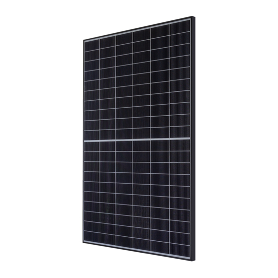
Summary of Contents for Panasonic EVERVOLT EVPV Series
- Page 1 General Installation Manual EVERVOLT™ PHOTOVOLTAIC MODULE EVPVXXX SERIES (WHITE BACK SHEET) EVPVXXXK SERIES (BLACK BACK SHEET)
-
Page 2: Table Of Contents
Contact Information Revision History Annex 1: Installations Using Module Level Power Electronics “EverVolt™” is a trademark of the Panasonic Group. Other product and service names listed in this manual are trademarks or registered trademarks of respective companies. General Installation Manual... -
Page 3: Safety Precautions
Do not junction box cover, nor remove Additional devices such as ground use the PV module and make any parts installed by Panasonic. fault, fuses, and disconnects may a replacement, when scratch There are no user serviceable parts be required. -
Page 4: Module Specifications
Module Specifications • Module specifications are shown in Table 1 and Figure 1. (Electrical specifications, mechanical specifications, module dimensions) • Under real conditions, a photovoltaic module may experience conditions that produce more current and/or voltage than reported at Standard Test Conditions. Therefore, the Isc value of modules should be multiplied by a factor of 1.25 to determine ampacity. - Page 5 Table 1. Model Specifications Electrical Specifications Model EVPV370 EVPV360 EVPV360K EVPV350K Back sheet color White White Black Black Rated Power, Watts (P 370W 360W 360W 350W Watt Class Sorting -0/+10W -0/+10W -0/+10W -0/+10W Maximum Power Voltage (V 37.4V 36.7V 36.7V 36.0V Maximum Power Current (I 9.90A...
-
Page 6: Standards
STANDARDS restrictions that may apply for connectors from Table 2. EVPVxxx and EVPVxxxK series comply roofmounted arrays. • All connectors and cables must with the requirements of UL61730. • The use of DC ground fault be secure and tight as well as interrupters is recommended. -
Page 7: Bypass Diode
Operating Conditions of circulation all around. This allows Panasonic modules are as follows: the connector to dry effectively and avoids the risk of damage or 1) The modules should be operated degradation of the connection only in terrestrial applications. -
Page 8: Module Installation
Mounting up to 7000 Pa (4666 Pa design load*) of the four marked zones shown hardware is not supplied by Panasonic. and upward pressure, e.g., wind, of below (Figure. 6). Ensure the mounting structure can... - Page 9 MOUNTING WITH CONTINOUS RAILS PARALLEL TO SHORT SIDE OF THE MODULE Continous rail spans the complete underside of the module. 27.4 in [695 mm] 27.4 in [695 mm] 23.8 in [605 mm] 23.8 in [605 mm] 22.2 in [565 mm] 22.2 in [565 mm] 13.4 in [340 mm] 13.4 in [340 mm]...
- Page 10 MOUNTING WITH CONTINOUS RAILS PARALLEL TO LONG SIDE OF THE MODULE A continous rail spans the complete underside of the module. 25.6 in [650 mm] 25.6 in [650 mm] Figure 8: Clamping of modules with rails parallel to long side of the module 0.8 - 1.6 in (20-40 mm) 1.6 - 2.4 in (40-60 mm) >2.4 in (>60 mm)
-
Page 11: Mounting With Short Rails
MOUNTING WITH SHORT RAILS A short rail is a rail with a min. length of 2 in (50 mm) that does not span the complete underside of a module. 27.4 in [695 mm] 27.4 in [695 mm] 23.8 in [605 mm] 23.8 in [605 mm] 22.2 in [565 mm] 22.2 in [565 mm]... -
Page 12: Mounting Methods: Mounting Holes
Scale: for downward pressure,e.g., snow, of e.g., aluminum or galvanized • Panasonic does not provide a 1:1.57 up to 5400 Pa (3600 Pa design load*) steel, and appropriate for the local warranty for clamps. The module and upward pressure,e.g., wind, of environment. -
Page 13: Wiring
• Do not insert PV cable between • Please contact your Panasonic back side and mounting structure Authorized Representative rail. When snow weight is applied with questions regarding other to the module, load may be applied electrical connections if needed. -
Page 14: Drainage Holes
DRAINAGE HOLES connection from the module frame. • Length of bolt should be carefully Local regulations may require selected in order to avoid • In each corner of the EverVolt grounding of the modules. contacting the back-sheet of the module frame small drainage •... -
Page 15: Maintenance
The return of any modules will not be water from the module glass. the hazards of electric shock or accepted by Panasonic unless prior • Take care not to scratch the surface injury. written authorization has been given by or introduce foreign elements that Panasonic. -
Page 16: Revision History
REVISION HISTORY Edition Revision Date Revised Item Revised Content 10.13.2020 General Installation Manual... -
Page 17: Annex 1: Installations Using Module Level Power Electronics
ANNEX 1: INSTALLATIONS USING manufacturer and the instructions in the diagram below (Figure 15): MODULE LEVEL POWER specific for EverVolt modules ELECTRONICS given below. Failure to follow the • To avoid damage to the module and manufacturer and the EverVolt to allow for thermal expansion, This section is applicable to EverVolt instructions may invalidate the... - Page 18 Panasonic Life Solutions Company of America All Rights Reserved © 2020 COPYRIGHT Panasonic Corporation Two Riverfront Plaza, Newark, NJ 07102 Specifications are subject to change without notice panasonicHIT@us.panasonic.com RS20183BRO-r6 na.panasonic.com/us/solar...


