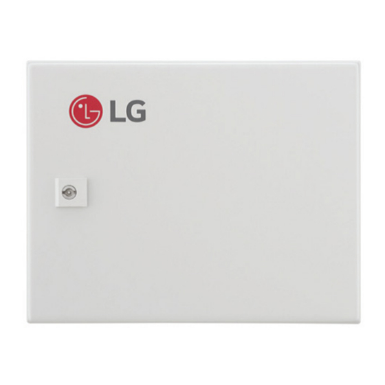
LG PAHCMS000 Service Manual
Hide thumbs
Also See for PAHCMS000:
- Installation manual (60 pages) ,
- Installation manual (47 pages) ,
- Owners & installation manual (7 pages)
Advertisement
SERVICE MANUAL
AIR
CONDITIONER
Please read this manual carefully before operating
your set and retain it for future reference.
Applied(AHU)
COMMUNICATION KIT
PAHCMR000, PAHCMS000
Copyright © 2017 LG Electronics Inc. All rights reserved. Only training and service purposes.
P/NO : MFL70041201
CONFIDENTIAL
www.lg.com
Advertisement

Summary of Contents for LG PAHCMS000
- Page 1 SERVICE MANUAL CONDITIONER Please read this manual carefully before operating your set and retain it for future reference. Applied(AHU) COMMUNICATION KIT PAHCMR000, PAHCMS000 Copyright © 2017 LG Electronics Inc. All rights reserved. Only training and service purposes. P/NO : MFL70041201 www.lg.com...
-
Page 2: Table Of Contents
Ventilation System Service Manual TABLE OF CONTENTS Safety Precautions....................3 Standards for Model ....................6 Functions & Accessory ..................7 Wiring Diagram ......................8 Disassembly Diagram (Deal Drawing) ..............9 Troubleshooting ....................13 - 2 -... -
Page 3: Safety Precautions
Safety Precautions Safety Precautions To prevent injury to the user or other people and property damage, the following instructions must be followed. n Incorrect operation due to ignoring instruction will cause harm or damage. The seriousness is classified by the following indications. - Page 4 Safety Precautions Do not use a defective or underrated circuit breaker. Use the correctly rated breaker and fuse. Otherwise there is a risk of fire or electric shock. Install the panel and the cover of control box securely. Otherwise there is risk of fire or electric shock due to dust, water etc.
- Page 5 Safety Precautions 1.2 Inspections after Repair Check to see if the terminal block is not dirty or loose. If terminal block is dust or loose it can cause an electrical shock or fire. Do not use a joined power cable or extension cable, or share the same power outlet with other electrical appliances.
-
Page 6: Standards For Model
Standards for Model Standards for Model AHCM Series 000 : Multi V, Single Model Classfication R :Return Air Control S :Supply Air Control Model Type AHCM : AHU Comm. Kit Accessory Type - 6 -... -
Page 7: Functions & Accessory
Functions & Accessory Functions & Accessory 1. Main Functions Model Functions PAHCMS000 PAHCMR000 Operation (on/off) Input Operation mode (cool/heat) Operation (on/off) Defrost signal Output Alarm signal Comp. status ODU Capacity control 3rd Party DDC interlock 2. Accessory Category Functions Model... -
Page 8: Wiring Diagram
Wiring Diagram Wiring Diagram Model : PAHCMR000 Model : PAHCMS000 - 8 -... - Page 9 Wiring Diagram n Main Module n Main Module - 9 -...
-
Page 10: Disassembly Diagram (Deal Drawing)
Disassembly Diagram (Deal Drawing) Disassembly Diagram (Deal Drawing) Model : PAHCMR000 263230B 263230A 263230C 247810A W4810 137215C 137215B 137215A - 10 -... - Page 11 Disassembly Diagram (Deal Drawing) SVC Parts List Quantity(Volume/Amount) Location Item Part No. Remarks PAHCMR000 137215A Panel Assembly,Control AGL75873901 137215B Panel Assembly,Control AGL75874301 137215C Panel Assembly,Control AGL76255601 W4810 Bracket MAZ64606301 247810A Controller Assembly ACM75139001 Comm. PCB 263230A Thermistor Assembly,NTC EBG62485901 263230B Thermistor Assembly,NTC EBG62485902 263230C...
- Page 12 Disassembly Diagram (Deal Drawing) Model : PAHCMS000 263230B 247810B 263230A 263230C 247810A W4810 W6631 137215C 137215B 137215A - 12 -...
- Page 13 Disassembly Diagram (Deal Drawing) SVC Parts List Quantity(Volume/Amount) Location Item Part No. Remarks PAHCMS000 137215A Panel Assembly,Control AGL75874001 137215B Panel Assembly,Control AGL75874302 137215C Panel Assembly,Control AGL76255701 W4810 Bracket MAZ64606301 247810A Controller Assembly ACM75139001 Comm. PCB 247810B Controller Assembly ACM75098801 Main PCB...
-
Page 14: Troubleshooting
Troubleshooting Troubleshooting 1.1 Error Indicator (Comm.Kit) Problem Cause Remedy Check the electrical connection and voltage of the No power supply power supply. Check the electrical connection of the AHU Communication Kit Wiring is wrong Communication Kit (Refer to the circuit diagram of does not work the Communication Kit) AHU Communication... - Page 15 Troubleshooting [Error Code (Outdoor Unit)] • This page is about outdoor error code. It can vary depending on outdoor unit. For more information, please refer to the outdoor unit manual. Display Title Cause of Error Outdoor unit Inverter Compressor IPM Outdoor unit Inverter Compressor Drive IPM Fault Fault Inverter Board Input Over Current(RMS) of...
- Page 16 Troubleshooting [Error Code (Outdoor Unit)] • This page is about outdoor error code. It can vary depending on outdoor unit. For more information, please refer to the outdoor unit manual. Display Title Cause of Error Outdoor unit Constant Speed Compressor1 Discharge Outdoor unit Constant Speed Compressor1 Discharge Temperature Sensor Fault Temperature Sensor open or short...
- Page 17 Troubleshooting [Error Code (Outdoor Unit)] • This page is about outdoor error code. It can vary depending on outdoor unit. For more information, please refer to the outdoor unit manual. Display Title Cause of Error Communication Error Between Failing to receive Slave Unit signal at main PCB Outdoor unit and Other Outdoor Unit of Outdoor unit Outdoor unit Fan PCB...


