
Related Manuals for Dell EMC PowerEdge MX840c


Summary of Contents for Dell EMC PowerEdge MX840c
- Page 1 Dell EMC PowerEdge MX840c Installation and Service Manual Regulatory Model: E05B Series Regulatory Type: E05B001 December 2020 Rev. A06...
- Page 2 A WARNING indicates a potential for property damage, personal injury, or death. © 2019 - 2020 Dell Inc. or its subsidiaries. All rights reserved. Dell, EMC, and other trademarks are trademarks of Dell Inc. or its subsidiaries. Other trademarks may be trademarks of their respective owners.
-
Page 3: Table Of Contents
Contents Chapter 1: About this document....................6 Chapter 2: Dell EMC PowerEdge MX840c overview............... 7 Front view of the sled................................ 8 Inside the sled..................................8 Locating the Service Tag of the sled..........................10 System information label..............................10 Chapter 3: Initial system setup and configuration................ 14 Setting up your sled................................14... - Page 4 Drive backplane..................................35 Drive backplane connectors............................35 Removing the drive backplane..........................36 Installing the drive backplane............................37 Cable routing..................................39 Drive cage................................... 42 Removing the drive cage............................42 Installing the drive cage............................. 43 Battery backup unit ................................. 44 Removing the battery backup unit module......................44 Installing the BBU module............................
- Page 5 System ID and status LED indicator codes....................... 104 Power button LED................................104 Drive indicator codes..............................105 System diagnostics................................. 106 Dell Embedded System Diagnostics........................106 Chapter 7: Getting help......................107 Contacting Dell................................. 107 Documentation feedback............................... 107 Receiving automated support with SupportAssist ....................107 Accessing system information by using QRL......................108...
-
Page 6: Chapter 1: About This Document
The PowerEdge MX840c is compatible with the PowerEdge MX7000 enclosure. For more information on the enclosure, refer to the Installation and Service Manual for the PowerEdge MX7000 at www.dell.com/poweredgemanuals. About this document... -
Page 7: Chapter 2: Dell Emc Poweredge Mx840C Overview
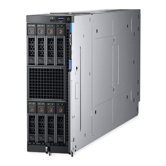
Dell EMC PowerEdge MX840c overview The PowerEdge MX840c is a double-width compute sled and supports: ● Up to four Intel Xeon Scalable Processors ● Up to 48 DIMM slots ● Up to eight 2.5 inch SAS, SATA (HDD/SSD), or NVMe drives... -
Page 8: Front View Of The Sled
For more information on the drives and ports, see the PowerEdge MX840c Technical Specs at www.dell.com/ poweredgemanuals Inside the sled NOTE: Components that are hot swappable have orange touch points and the components that are not hot swappable have blue touch points. Dell EMC PowerEdge MX840c overview... - Page 9 6. Rotational guiding hook 7. Power connector 8. Mezzanine card (Fabric B1 card) 9. Mini Mezzanine card (Fabric C1 card) connector 10. iDRAC card 11. IDSDM/BOSS module connector 12. System board 13. PERC card connector Dell EMC PowerEdge MX840c overview...
-
Page 10: Locating The Service Tag Of The Sled
The PowerEdge MX840c sled is identified by a unique Express Service Code and Service Tag number. The Express Service Code and Service Tag are found on the front of the enclosure by pulling out the Information Tag. Dell uses this information to route support calls to the appropriate personnel. - Page 11 Figure 6. PowerEdge MX840c memory information Dell EMC PowerEdge MX840c overview...
- Page 12 Figure 7. PowerEdge MX840c system board connections Figure 8. PowerEdge MX840c BBU module Dell EMC PowerEdge MX840c overview...
- Page 13 Figure 9. PowerEdge MX840c PEM removal Figure 10. PowerEdge MX840c mezzanine cards removal Figure 11. PowerEdge MX840c PERC cards removal Figure 12. PowerEdge MX840c iDRAC/IDSDM module and optional internal USB key removal Dell EMC PowerEdge MX840c overview...
-
Page 14: Chapter 3: Initial System Setup And Configuration
The Integrated Dell Remote Access Controller (iDRAC) is designed to make system administrators more productive and improve the overall availability of Dell systems. iDRAC alerts administrators about system issues and enables them to perform remote system management. This reduces the need for physical access to the system. -
Page 15: Log In To Idrac
For more information about drivers, documentation, and white papers on the Intel® QAT, see https://01.org/intel- quickassist-technology. For more information about logging in to the iDRAC and iDRAC licenses, see the latest Integrated Dell Remote Access Controller User's Guide at www.dell.com/poweredgemanuals You can also access iDRAC by using RACADM. -
Page 16: Downloading Drivers And Firmware
Using iDRAC virtual media www.dell.com/idracmanuals Downloading drivers and firmware Dell EMC recommends that you download and install the latest BIOS, drivers, and systems management firmware on your system. Prerequisites Ensure that you clear the web browser cache before downloading the drivers and firmware. -
Page 17: Chapter 4: Installing And Removing Sled Components
Damage due to servicing that is not authorized by Dell is not covered by your warranty. Read and follow the safety instructions that are shipped with your product. -
Page 18: Before Working Inside Your Sled
Before working inside your sled Prerequisites Follow the safety guidelines listed in the Safety instructions section. Steps 1. Power off the sled. 2. Remove the sled from the enclosure. 3. If applicable, install the I/O connector cover. CAUTION: To prevent damage to the I/O connectors on the sled, ensure that you cover the connectors when you remove the sled from the enclosure. - Page 19 2. Power off the sled. Steps 1. Press the blue lever button on the sled to release the lever. 2. Holding the release lever, slide the sled out of the enclosure. Figure 13. Removing the sled from the enclosure NOTE: Support the sled with both hands while sliding it out of the enclosure.
-
Page 20: Installing The Sled Into The Enclosure
Figure 14. Installing the I/O connector cover on the sled CAUTION: If you are permanently removing the sled, install a blank. Operating the enclosure for extended periods of time without a blank installed can cause the enclosure to overheat. NOTE: The color of the I/O connector cover may differ. - Page 21 Figure 15. Removing the I/O connector cover from the sled NOTE: The color of the I/O connector cover may differ. 2. Press the blue lever button on the sled to release the lever. 3. Holding the sled with two hands, align the sled with the bay in the enclosure and slide the sled into the enclosure until firmly seated.
-
Page 22: Sled Cover
Next steps 1. Power on the sled. Sled cover The sled cover protects the components inside the sled and helps in maintaining air flow inside the sled. Removing the sled cover Prerequisites 1. Follow the safety guidelines listed in the Safety instructions section. - Page 23 Steps 1. Align the tabs on the sled cover with the guide slots on the sled. 2. Slide the cover towards the front of the sled until it locks in place. Figure 18. Installing the sled cover Next steps Install the sled into the enclosure.
-
Page 24: Air Shroud
Air shroud The air shroud aerodynamically directs the airflow across the entire sled. The airflow passes through all the critical parts of the sled thus allowing increased cooling. The PowerEdge MX840c sled has: ● Air shroud on the processor expansion module (PEM) ●... -
Page 25: Removing The Air Shroud From The System Board
Steps 1. Align the tabs on the air shroud with the slots on the PEM. 2. Place the air shroud on the PEM. Figure 20. Installing the air shroud on the PEM Next steps 1. Follow the procedure listed in the After working inside your sled section. -
Page 26: Installing The Air Shroud On The System Board
Figure 21. Removing the air shroud from the system board Next steps Install the air shroud on the system board. Installing the air shroud on the system board Prerequisites 1. Follow the safety guidelines listed in the Safety instructions section. 2. -
Page 27: Processor Expansion Module
Figure 22. Installing the air shroud on the system board Next steps Install the PEM. 2. Follow the procedure listed in the After working inside your sled section. Processor expansion module Removing the processor expansion module Prerequisites 1. Follow the safety guidelines listed in the Safety instructions section. -
Page 28: Installing The Processor Expansion Module
Figure 23. Removing the PEM Next steps Installing the processor expansion module. Installing the processor expansion module Prerequisites 1. Follow the safety guidelines listed in the Safety instructions section. 2. Follow the procedure listed in the Before working inside your sled section. -
Page 29: Drives
Figure 24. Installing the PEM Next steps 1. Connect the cable on the PEM to the backplane. Install the air shroud on the PEM. 3. Follow the procedure listed in the After working inside your sled section. Drives Drive installation guidelines Drives are available in hot-swappable drive carriers that fit in the front drive slots of the PowerEdge MX840c sled. -
Page 30: Installing A Drive Blank
CAUTION: Mixing drive blanks from previous generations of PowerEdge servers is not supported. Steps Press the release button, and slide the drive blank out of the drive slot. Figure 25. Removing a drive blank Next steps Install a drive or a drive blank. -
Page 31: Removing A Drive Carrier
Figure 26. Installing a drive blank Removing a drive carrier Prerequisites 1. Follow the safety guidelines listed in the Safety instructions section. 2. Using the management software, prepare the drive for removal. If the drive is online, the green activity or fault indicator flashes while the drive is turning off. When the drive indicators are off, the drive is ready for removal. -
Page 32: Installing A Drive Carrier
Figure 27. Removing a drive carrier Next steps Install a drive carrier. 2. If you are not replacing the drive carrier immediately, insert a drive blank in the empty drive slot to maintain proper sled cooling. Installing a drive carrier Prerequisites CAUTION: Before attempting to remove or install a drive while the system is running, see the documentation for... -
Page 33: Removing A Drive From The Drive Carrier
Steps 1. Press the release button on the front of the drive carrier to open the release handle. 2. Insert the drive carrier into the drive slot and slide until the drive carrier connects with the backplane. 3. Close the release handle of the drive carrier to lock the drive in place. Figure 28. -
Page 34: Installing A Drive Into The Drive Carrier
Figure 29. Removing a drive from the drive carrier Next steps Install a drive into the drive carrier. Installing a drive into the drive carrier Prerequisites 1. Follow the safety guidelines listed in the Safety instructions section. CAUTION: Mixing drive carriers from other generations of PowerEdge servers is not supported. NOTE: When installing a drive into the drive carrier, ensure that the screws are torqued to 4 in-lbs. -
Page 35: Drive Backplane
Figure 30. Installing a drive into the drive carrier Drive backplane Drive backplane connectors Depending on the configuration, the drives supported on the PowerEdge MX840c sled are listed in the table. Table 3. Supported drives options for the PowerEdge MX840c sled Drives Specifications Eight drives... -
Page 36: Removing The Drive Backplane
Figure 31. 6 x 2.5 inch drive backplane 1. AUX 3 cable connector 2. SATA/SAS connector 3. I2C cable connector 4. AUX 2 cable connector 5. AUX 1 cable connector 6. Power cable connector [BP PWR] Figure 32. 8 x 2.5 inch drive backplane 1. -
Page 37: Installing The Drive Backplane
6. Disconnect the cables that are connected to the drive backplane. Steps 1. Using Phillips #2 screwdriver, loosen the two captive screws on the drive backplane. 2. Holding the edges, lift the backplane away from the sled. Figure 33. Removing the drive backplane Next steps Install the drive backplane. - Page 38 Figure 34. Installing the drive backplane Next steps 1. Connect all the cables to the drive backplane connectors. Install the drives. Install the PEM. Install the air shroud on the PEM. 5. Follow the procedure listed in the After working inside your sled section.
-
Page 39: Cable Routing
Cable routing Figure 35. Cable routing - 6 x 2.5 inch drive backplane with PERC card Figure 36. Cable routing - 6 x 2.5 inch drive backplane with Jumbo PERC card Installing and removing sled components... - Page 40 Figure 37. Cable routing - 6 x 2.5 inch drive backplane Figure 38. Cable routing - 6 x 2.5 inch drive backplane with PEM board Installing and removing sled components...
- Page 41 Figure 39. Cable routing - 8 x 2.5 inch drive backplane with PERC card Figure 40. Cable routing - 8 x 2.5 inch drive backplane with Jumbo PERC card Installing and removing sled components...
-
Page 42: Drive Cage
Figure 41. Cable routing - 8 x 2.5 inch drive backplane Figure 42. Cable routing - 8 x 2.5 inch drive backplane with PEM board Drive cage The drive cage contains the drives and the battery backup unit module. Removing the drive cage Prerequisites CAUTION: To prevent damage to the drives and backplane, you must remove the drives from the sled before... -
Page 43: Installing The Drive Cage
NOTE: Observe the routing of the cables on the sled as you remove them from the sled. You must route these cables properly when you replace them to prevent the cables from being pinched or crimped. 1. Follow the safety guidelines listed in the Safety instructions section. -
Page 44: Battery Backup Unit
1. Follow the safety guidelines listed in the Safety instructions section. 2. Follow the procedure listed in the Before working inside your sled section. Steps 1. Place the drive cage into the sled, aligning with the screw holes on the sled. 2. -
Page 45: Installing The Bbu Module
Remove the drive cage. Steps 1. Press the tab on the side and push the BBU module from the rear end of the drive cage to release the BBU module. 2. Holding the BBU module by the edges, slide the BBU module out of the drive cage. Figure 45. -
Page 46: Removing The Bbu From The Bbu Cage
Figure 46. Installing the BBU module 3. Connect the cables on the BBU to the connectors on the system board. Next steps Install the PEM. 2. Follow the procedure listed in the After working inside your sled section. Removing the BBU from the BBU cage Prerequisites 1. -
Page 47: Installing The Bbu Into The Bbu Cage
Figure 47. Removing the BBU from the BBU cage Next steps Install the BBU into the BBU cage. Installing the BBU into the BBU cage Prerequisites 1. Follow the safety guidelines listed in the Safety instructions section. 2. Follow the procedure listed in the Before working inside your sled section. -
Page 48: Control Panel
Figure 48. Installing the BBU into the BBU cage Next steps Install the BBU module. Control panel A control panel enables you to manually control the inputs to the sled. The control panel features on the PowerEdge MX840c are: ● Power button ●... -
Page 49: Installing The Control Panel
Figure 49. Removing the control panel Next steps Install the control panel. Installing the control panel Prerequisites 1. Follow the safety guidelines listed in the Safety instructions section. 2. Follow the procedure listed in the Before working inside your sled section. -
Page 50: System Memory
Figure 50. Installing the control panel Next steps Install the BBU module. Install the drive cage. Install the backplane. Install the drives. Install the PEM. 6. Follow the procedure listed in the After working inside your sled section. System memory The sled supports DDR4 registered DIMMs (RDIMMs), load reduced DIMMs (LRDIMMs), Non-Volatile DIMMs (NVDIMM-Ns), and Intel Optane Data Center Persistent Memory Modules (DCPMMs) . - Page 51 Your system contains 24 memory sockets that are split into two sets of 12 sockets, one set per processor. Each 12-socket set is organized into six channels. Six memory channels are allocated to each processor. In each channel, the release tabs of the first socket are marked white, and the second socket black.
- Page 52 Figure 52. Memory sockets on the PEM board Memory channels are organized as follows: Table 4. Memory channels Processor Channel 0 Channel 1 Channel 2 Channel 3 Channel 4 Channel 5 Processor 1 Slots A1 and A7 Slots A2 and A8 Slots A3 and A9 Slots A4 and Slots A5 and A11 Slots A6 and...
-
Page 53: General Memory Module Installation Guidelines
Table 5. Memory population DIMM Type DIMM Ranking Operating Frequency (in Voltage MT/s) RDIMM 1R/2R 1.2 V 2933, 2666 LRDIMM 4R/8R 1.2 V 2666 General memory module installation guidelines To ensure optimal performance of your system, observe the following general guidelines when configuring your system memory. If your system's memory configurations fail to observe these guidelines, your system might not boot, stop responding during memory configuration, or operate with reduced memory. -
Page 54: Nvdimm-N Memory Module Installation Guidelines
● All slots on configurations 3, 6, 9, and 12 can be used, but a maximum of 12 NVDIMM-Ns can be installed in a system. NOTE: NVDIMM-N memory slots are not hot-pluggable. For more information about the supported NVDIMM-N configurations, see the NVDIMM-N User Guide at www.dell.com/ poweredgemanuals. Table 6. Supported NVDIMM-N for dual processor configurations Configuration... - Page 55 Table 6. Supported NVDIMM-N for dual processor configurations (continued) Configuration Description Memory population rules RDIMMs NVDIMM-N Processor2 {B1, 2, 3, 4, 5, 6, 7, 8, 9, 10} Configuration 10 12x 16 GB RDIMMs, 6x Same for all 12x RDIMM Processor1 {A7, 8, 9} NVDIMM-Ns configurations.
- Page 56 Table 7. Supported NVDIMM-N for quad processor configurations (continued) Memory population rules Configuration Description RDIMMs NVDIMM-N Configuration 5 24x 32 GB RDIMMs, 2x Processor1 {A1, 2, 3, 4, 5, 6}, Processor1 {A7}, NVDIMM-Ns Processor2 {B1, 2, 3, 4, 5, 6}, Processor2 {B7} Processor3 {C1, 2, 3, 4, 5, 6} Processor4 {D1, 2, 3, 4, 5, 6}...
-
Page 57: Dcpmm Installation Guidelines
● Mixing different capacities of RDIMMs and LRDIMMs are not allowed when DCPMM is installed. ● DCPMMs of different capacities are not allowed. For more information about the supported DCPMM configurations, see the Dell EMC DCPMM User 's Guide at https:// www.dell.com/support/home/products/server_int/server_int_poweredge. - Page 58 Table 8. 2 socket DCPMM configurations (continued) No. of DCPM DRAM DRAM DCPM Operating Total Total Ratio Requi Suppor Suppor CPUs Populat Capaci system Memory Memor DRAM to ted in ted in in the Populat Capaci Memory in (GB) y per Optane an M Memor...
-
Page 59: Mode-Specific Guidelines
Table 9. 4 socket DCPMM configurations No. of DCPMM DRAM DRAM DCPMM Operati Total Total Ratio Require Support Support CPUs in Populat Populat Capacit Capacit Memory Memory DRAM s an M ed in ed in y (GB) y (GB) system (GB) or L Memory... - Page 60 Dell Fault Resilient Mode The Dell Fault Resilient Mode if enabled, the BIOS creates an area of memory that is fault resilient. This mode can be used by an OS that supports the feature to load critical applications or enables the OS kernel to maximize system availability.
- Page 61 Optimizer Mode This mode supports Single Device Data Correction (SDDC) only for memory modules that use x4 device width. It does not impose any specific slot population requirements. ● Dual processor: Populate the slots in round robin sequence starting with processor 1. NOTE: Processor 1 and processor 2 population should match.
-
Page 62: Removing A Memory Module
Table 11. Memory population rules (continued) Processor Configuration Memory population Memory population information processor 2, NOTE: Odd number of DIMMs will result in A{3}, B{3} C{3}, D{3}, processor 3, and unbalanced memory configurations, which A{4}, B{4} C{4}, D{4} processor 4 in turn will result in performance loss. -
Page 63: Installing A Memory Module
Remove memory module blanks only if you intend to install memory modules in those sockets. NOTE: You must follow the thermal restriction while using DIMM blank. For information about thermal restriction, see the PowerEdge MX840c Technical Specs at www.dell.com/poweredgemanuals Steps 1. Locate the appropriate memory module socket. CAUTION: Handle each memory module only by the card edges, ensuring not to touch the middle of the memory module or metallic contacts. -
Page 64: Processors And Heat Sinks
Steps 1. Locate the appropriate memory module socket. CAUTION: Handle each memory module only by the card edges, ensuring not to touch the middle of the memory module or metallic contacts. CAUTION: To prevent damage to the memory module or the memory module socket during installation, do not bend or flex the memory module. -
Page 65: Processor Wattage And Heat Sink Dimensions
The heat sink absorbs the heat generated by the processor, and helps the processor to maintain its optimal temperature level. Processor wattage and heat sink dimensions Table 12. Processor wattage and heat sink dimensions Processor Processor type Heat sink width Number of DIMMs, Number of DIMMs, configuration... -
Page 66: Removing The Processor From The Processor And Heat Sink Module
Figure 55. Removing the processor and heat sink module Next steps Install the processor and heat sink module. Removing the processor from the processor and heat sink module Prerequisites NOTE: Only remove the processor from the processor and heat sink module (PHM) if you are replacing the processor or heat sink. -
Page 67: Installing The Processor Into A Processor And Heat Sink Module
Figure 56. Loosening the processor bracket 4. Lift the bracket and the processor away from the heat sink, and place the processor connector side down on the processor tray. 5. Flex the outer edges of the bracket to release the bracket from the processor. NOTE: Ensure that the processor and the bracket are placed in the tray after you remove the heat sink. - Page 68 2. Follow the procedure listed in the Before working inside your sled section. Steps 1. Place the processor in the processor tray. NOTE: Ensure that the pin 1 indicator on the processor tray is aligned with the pin 1 indicator on the processor. 2.
- Page 69 Figure 59. Applying thermal grease on top of the processor 5. Place the heat sink on the processor and push down on the base of the heat sink until the bracket locks onto the heat sink. NOTE: ● Ensure that the two guide pin holes on the bracket match the guide holes on the heat sink. ●...
-
Page 70: Installing The Processor And Heat Sink Module
Figure 60. Installing the heat sink onto the processor Next steps Install the processor and heat sink module. 2. Follow the procedure listed in the After working inside your sled section. Installing the processor and heat sink module Prerequisites CAUTION: Never remove the heat sink from a processor unless you intend to replace the processor. -
Page 71: Idrac Card
a. Loosen both the heat sink screws completely. b. Lower the PHM on to the blue retention clips, following the procedure described in step 2. c. Secure the PHM to the system board or PEM, following the replacement instructions listed in step 3 above. NOTE: The processor and heat sink module retention screws should not be tightened to more than 0.11 kgf-m (1.13 N.m or 10+/-0.2 in-lbf). -
Page 72: Installing The Idrac Card
Steps Hold the blue pull tag, and lift the iDRAC card away from the sled. Figure 62. Removing the iDRAC card NOTE: The iDRAC card is not swappable with other MX series sleds in the MX7000 enclosure. NOTE: The procedure to remove vFlash card is similar to removing a MicroSD card. - Page 73 CAUTION: If either the system board or iDRAC card fails, it is required to replace the system board and iDRAC card simultaneously. Steps 1. Align the iDRAC card with the connector and guide pin on the system board. 2. Lower the iDRAC card on the system board connector and press the blue push points until the iDRAC card is firmly seated on the system board connector.
-
Page 74: Perc Cards
PERC cards The PowerEdge MX840c sled includes dedicated slots on the system board and PEM board for PERC cards. Removing the PERC card Prerequisites 1. Follow the safety guidelines listed in the Safety instructions section. 2. Follow the procedure listed in the Before working inside your sled section. -
Page 75: Removing The Jumbo Perc Card
Figure 67. Installing the PERC card Next steps 1. Connect the cable to the PERC card. Install the PEM. 3. Follow the procedure listed in the After working inside your sled section. Removing the Jumbo PERC card Prerequisites 1. Follow the safety guidelines listed in the Safety instructions section. -
Page 76: Installing The Jumbo Perc Card
Figure 68. Removing the Jumbo PERC card Next steps Install the Jumbo PERC card. Installing the Jumbo PERC card Prerequisites 1. Follow the safety guidelines listed in the Safety instructions section. 2. Follow the procedure listed in the Before working inside your sled section. -
Page 77: Optional Internal Dual Sd Module
Figure 69. Installing the Jumbo PERC card Next steps 1. Connect the cable to the Jumbo PERC card. Install the air shroud on the system board. Install the PEM. 4. Follow the procedure listed in the After working inside the sled section. -
Page 78: Installing The Optional Idsdm Module
Figure 70. Removing the IDSDM module Next steps Install the optional IDSDM module. Installing the optional IDSDM module Prerequisites 1. Follow the safety guidelines listed in the Safety instructions section. 2. Follow the procedure listed in the Before working inside your sled section. -
Page 79: Removing A Microsd Card
Figure 71. Installing the IDSDM module Next steps Install the MicroSD cards. NOTE: Reinstall the MicroSD cards into the same slots based on the labels you had marked on the cards during removal. Install the air shroud on the system board. -
Page 80: Installing A Microsd Card
Figure 72. Removing a MicroSD card Next steps Install a MicroSD card. Installing a MicroSD card Prerequisites 1. Follow the safety guidelines listed in the Safety instructions section. 2. Follow the procedure listed in the Before working inside your sled section. -
Page 81: M.2 Boss Module
Figure 73. Installing a MicroSD card Next steps Install the IDSDM module. Install the PEM. 3. Follow the procedure listed in the After working inside your sled section. M.2 BOSS module The M.2 BOSS module is a simple RAID solution designed specifically for booting a server's operating system. The module supports up to two 6 Gbps M.2 SATA cards. -
Page 82: Installing The M.2 Boss Module
Figure 74. Removing the M.2 BOSS module Next steps Install the M.2 BOSS module. Installing the M.2 BOSS module Prerequisites 1. Follow the safety guidelines listed in the Safety instructions section. 2. Follow the procedure listed in the Before working inside your sled. -
Page 83: Removing The M.2 Sata Card
Figure 75. Installing the M.2 BOSS module Next steps Install the air shroud on the system board. Install the PEM. 3. Follow the procedure listed in the After working inside your sled. Removing the M.2 SATA card Prerequisites 1. Follow the safety guidelines listed in the Safety instructions section. -
Page 84: Installing The M.2 Sata Card
Figure 76. Removing the M.2 SATA card Next steps Install the M.2 SATA card. Installing the M.2 SATA card Prerequisites 1. Follow the safety guidelines listed in the Safety instructions section. 2. Follow the procedure listed in the Before working inside your sled. -
Page 85: Mezzanine Card
Figure 77. Installing the M.2 SATA card Next steps Install the M.2 BOSS module. Install the PEM. 3. Follow the procedure listed in the After working inside your sled. Mezzanine card Mezzanine card installation guidelines The PowerEdge MX840c sled supports four Mezzanine cards: ●... -
Page 86: Installing The Mini Mezzanine Card Blank
Figure 78. Removing the mini Mezzanine card blank Next steps Install the mini Mezzanine card blank. Installing the mini Mezzanine card blank Prerequisites 1. Follow the safety guidelines listed in the Safety instructions section. 2. Follow the procedure listed in the Before working inside your sled section. -
Page 87: Removing A Mini Mezzanine Card
2. Follow the procedure listed in the After working inside the sled section. Removing a mini Mezzanine card Prerequisites 1. Follow the safety guidelines listed in the Safety instructions section. 2. Follow the procedure listed in the Before working inside a sled section. -
Page 88: Removing The Mezzanine Card
Figure 81. Installing the mini Mezzanine card NOTE: The PowerEdge MX840c sled supports HBA330 MMZ and Fiber channel MMZ which are installed in the mini Mezzanine card slot. Next steps Install the air shroud on the system board. Install the PEM. - Page 89 Figure 82. Removing the Mezzanine card from the system board Figure 83. Removing the Mezzanine card from the PEM Next steps Install the Mezzanine card. Installing and removing sled components...
-
Page 90: Installing The Mezzanine Card
Installing the Mezzanine card Prerequisites 1. Follow the safety guidelines listed in the Safety instructions section. 2. Follow the procedure listed in the Before working inside your sled section. Steps 1. Align the connector on the Mezzanine card with the connector on the system board. 2. -
Page 91: Optional Internal Usb Memory Key
Figure 85. Installing the Mezzanine card on the PEM Next steps 1. After installing the Mezzanine card on the system board, install the PEM. 2. Follow the procedure listed in the After working inside your sled section. Optional internal USB memory key An optional USB memory key installed inside your sled can be used as a boot device, security key, or mass storage device. -
Page 92: System Battery
Steps 1. Locate the USB port or USB memory key on the system board. To locate the USB port, see the System board jumpers and connectors section. 2. If installed, remove the USB memory key from the USB port. 3. Place the replacement USB memory key into the USB port. Next steps Install the PEM. -
Page 93: System Board
Figure 87. Installing the system battery Next steps Install the PEM. 2. Follow the procedure listed in the After working inside your sled section. 3. While booting, press F2 to enter the System Setup and ensure that the battery is operating properly. 4. - Page 94 Internal USB memory key (if applicable) iDRAC card PERC cards Jumbo PERC card Mezzanine card NOTE: It is required to remove the mezzanine card support brackets for removing the system board from the system. Mini Mezzanine cards Memory modules and memory module blanks Drives Backplane Control panel...
-
Page 95: Installing The System Board
Installing the system board Prerequisites 1. Follow the safety guidelines listed in the Safety instructions section. 2. Follow the procedure listed in the Before working inside your sled section. CAUTION: If either the system board or iDRAC card fails, it is required to replace the system board and iDRAC card simultaneously. - Page 96 Service Tag. After the Service Tag is entered, it cannot be updated or changed. 5. Click OK. 6. Import your new or existing iDRAC Enterprise license. For more information, see the Integrated Dell Remote Access Controller User's Guide at www.dell.com/poweredgemanuals Restoring the Service Tag by using the Easy Restore feature By using the Easy Restore feature, you can restore your Service Tag, license, UEFI configuration, and the system configuration data after replacing the system board.
-
Page 97: Trusted Platform Module
2. Perform one of the following steps: ● Press Y to restore the Service Tag, license, and diagnostics information. ● Press N to navigate to the Dell Lifecycle Controller based restore options. ● Press F10 to restore data from a previously created Hardware Server Profile. - Page 98 Installing the TPM Steps 1. To install the TPM, align the edge connectors on the TPM with the slot on the TPM connector. 2. Insert the TPM into the TPM connector such that the plastic rivet aligns with the slot on the system board. 3.
- Page 99 2. On the System Setup Main Menu screen, click System BIOS > System Security Settings. 3. From the TPM Security option, select On. 4. Save the settings. 5. Restart your system. 6. Enter System Setup again. 7. On the System Setup Main Menu screen, click System BIOS > System Security Settings. 8.
-
Page 100: Chapter 5: Jumpers And Connectors
Jumpers and connectors This topic provides specific information about the jumpers. It also provides some basic information about jumpers and switches and describes the connectors on the various boards in the system. Jumpers on the system board help to disable the system and setup passwords. - Page 101 Table 13. System board jumpers and connectors (continued) Item Connector Description BBU_SIGNAL Battery Backup Unit (BBU) signal connector CPU1 Processor 1 A6, A12, A5, A11, A4, A10 Memory module sockets B3, B9, B2, B8, B1, B7 Memory module sockets J_MEZZ_A1 (CPU1) Mezzanine card (Fabric A1 card) connector CPU2...
-
Page 102: System Board Jumper Settings
Damage due to servicing that is not authorized by Dell is not covered by your warranty. Read and follow the safety instructions that are shipped with your product. - Page 103 Steps Remove the sled from the enclosure. Remove the sled cover. Remove the PEM. Remove the drive cage. 5. Move the jumper on the system board jumper from pins 2 and 4 to pins 4 and 6. Install the drive cage.
-
Page 104: Chapter 6: System Diagnostics And Indicator Codes
System diagnostics and indicator codes The diagnostic indicators on the system front panel display system status during system startup. Topics: • System ID and status LED indicator codes • Power button LED • Drive indicator codes • System diagnostics System ID and status LED indicator codes The system ID indicator is located on the control panel of your sled. -
Page 105: Drive Indicator Codes
Table 17. Power button LED Power button LED indicator code Condition Sled is not operating, regardless of power supply available. Sled is operating, one or more of the non-standby power supplies are active. Slowly blinking Sled is performing powering on sequence and iDRAC is still booting. -
Page 106: System Diagnostics
System diagnostics If you experience a problem with your system, run the system diagnostics before contacting Dell for technical assistance. The purpose of running system diagnostics is to test your system hardware without using additional equipment or risking data loss. If you are unable to fix the problem yourself, service and support personnel can use the diagnostics results to help you solve the problem. -
Page 107: Chapter 7: Getting Help
Dell product catalog. Availability varies by country and product, and some services may not be available in your area. To contact Dell for sales, technical assistance, or... -
Page 108: Accessing System Information By Using Qrl
Dell EMC. This information is used by Dell EMC Technical Support to troubleshoot the issue. ● Proactive contact — A Dell EMC Technical Support agent contacts you about the support case and helps you resolve the issue. -
Page 109: Chapter 8: Documentation Resources
This section provides information about the documentation resources for your system. To view the document that is listed in the documentation resources table: ● From the Dell EMC support site: 1. Click the documentation link that is provided in the Location column in the table. - Page 110 Methods to download firmware drivers section this document. Managing your For information about systems www.dell.com/poweredgemanuals system management software offered by Dell, see the Dell OpenManage Systems Management Overview Guide. For information about setting up, www.dell.com/ using, troubleshooting openmanagemanuals > OpenManage, Dell...
- Page 111 Table 19. Additional documentation resources for your system (continued) Task Document Location generated by the system firmware and agents that monitor system components, see the Error Code Lookup. Troubleshooting your For information about identifying www.dell.com/poweredgemanuals system troubleshooting PowerEdge server issues, see the Server Troubleshooting Guide. Documentation resources...